EP0325809A2 - Méthode et système d'imprimerie à diffusion multisurface - Google Patents
Méthode et système d'imprimerie à diffusion multisurface Download PDFInfo
- Publication number
- EP0325809A2 EP0325809A2 EP88202750A EP88202750A EP0325809A2 EP 0325809 A2 EP0325809 A2 EP 0325809A2 EP 88202750 A EP88202750 A EP 88202750A EP 88202750 A EP88202750 A EP 88202750A EP 0325809 A2 EP0325809 A2 EP 0325809A2
- Authority
- EP
- European Patent Office
- Prior art keywords
- key
- printing
- sheet
- members
- engagement
- Prior art date
- Legal status (The legal status is an assumption and is not a legal conclusion. Google has not performed a legal analysis and makes no representation as to the accuracy of the status listed.)
- Withdrawn
Links
Images


Classifications
-
- B—PERFORMING OPERATIONS; TRANSPORTING
- B41—PRINTING; LINING MACHINES; TYPEWRITERS; STAMPS
- B41F—PRINTING MACHINES OR PRESSES
- B41F17/00—Printing apparatus or machines of special types or for particular purposes, not otherwise provided for
- B41F17/006—Printing apparatus or machines of special types or for particular purposes, not otherwise provided for for printing on curved surfaces not otherwise provided for
-
- B—PERFORMING OPERATIONS; TRANSPORTING
- B41—PRINTING; LINING MACHINES; TYPEWRITERS; STAMPS
- B41F—PRINTING MACHINES OR PRESSES
- B41F16/00—Transfer printing apparatus
Definitions
- the present invention relates to an apparatus and method for imprinting images or indicia on the keycaps of keyboards, and more particularly to the imprinting of such images on the top and on at least one side surface of the keycaps.
- U.S. Patent 4,664,030--Siverson et al there is provided a base member having a plurality of spring loaded pedestals on which the keys or keycaps to be imprinted are placed.
- a locator plate with openings to receive the keys is placed over the keys to keep these in a fixed position, and also to function as a heat shield.
- a sheet of transfer paper with the images thereon is located above the keys and in proper alignment therewith. U-shaped cuts or incisions are made around the areas of the images.
- a printing plate positioned above the keys and above the paper, and this has a plurality of protrusions, each of which has two surface portions, namely, a downwardly facing surface portion to engage the paper over a top surface of the key, and also a slanted surface portion to press parts of the paper downwardly against the slanted front surface of the key.
- the printing plate is attached to the bottom of a heated platen, and the platen with the printing plate is moved downwardly to press a rubber sheet against the transfer paper which in turn is pressed against the keys.
- Each of the protrusions presses a portion of the transfer paper into engagement with its related key so that one part of each portion of the transfer sheet engages the top surface of the key, while a second part of that portion of the transfer sheet engages the slanted surface portion of the key, so as to transfer one image to a top key surface and another to the front key surface.
- U.S. 4,670,084--Durand Another system for transferring images from a sheet onto a set of keys is shown in U.S. 4,670,084--Durand.
- a resiliantly flexible membrane is positioned over the sheet on which the images are imprinted.
- radiant heating elements are used to heat the membrane after the vacuum assembly has been actuated to transfer the dye on the sheet to the keys so as to imprint the images on the keys.
- the apparatus and method of the present invention is particularly adapted to imprint images on at least one key member of a keyboard (and desirably on a plurality of key members as part of a single operation), where a first image is imprinted on a top surface of the key member, and a second image is printed on a side surface of the key member, which in this exemplary embodiment is the front surface of the key member. This is done in a manner so that the first and second images are precisely located relative to the top and side surfaces.
- the apparatus comprises a support means adapted to support at a predetermined key location at least one key member on which the images are to be imprinted, and in the preferred embodiment on a plurality of such key members.
- the first printing component has a first contact surface (and desirably a plurality of contact surfaces) at a location corresponding to said key location (or locations) to come into pressing engagement with the top key member surface at the key location.
- a second printing component has a second contact surface (and desirably a plurality of such surfaces) at a location (or locations) corresponding to said key location (or locations) to come into pressing engagement with the side key member surface.
- locating means to locate between said support means and said printing assembly a printing sheet having a surface region which has thereon related images at an image location corresponding to the key location.
- the sheet region has first and second sheet portions with the first and second images thereon respectively.
- actuating means to bring said support means and said printing assembly into operating engagement where the printing assembly presses the printing sheet into engagement with the key member (or key members) in a manner that the first contact surface initially presses the first sheet portion into pressing engagement with the top key member surface, after which the second contact surface moves relative to the key member to move the second sheet portion into pressing engagement with the side key member surface.
- a flexible and stretchable cushioning sheet member positioned between the support means and the printing assembly in a manner that the first and second contact surfaces press the cushioning sheet member against the printing sheet to cause the sheet region (or regions) to come into engagement with the key member (or members).
- heating means to heat said first and second printing components so that said first and second printing components in turn cause the sheet region and the key member to be heated to cause the images on the sheet member to be transferred to the key member.
- the apparatus there is mounting means to which the first and second printing components are mounted in a manner so as to be movable relative to one another.
- the mounting means is arranged to be movable, relative to the support means, toward and away from the support means.
- the apparatus is arranged so that as the actuating means moves said mounting means toward the support means, the first printing component first comes into operating engagement with the key member (or members), after which the mounting means continues to move the second printing component into operating engagement with the key members. This is done in a manner that when the first printing component comes into operating engagement with the key members, the mounting means moves relative to the first printing component to bring the second printing component into operating engagement with the key members.
- the second printing component is mounted so as to remain stationary relative to said mounting means.
- the spring means engages the first printing component in a manner to urge the first printing component toward the key members.
- the spring means continues to urge the first printing component into operating engagement with the key members as the mounting means continues to move the second printing component into operating engagement with the key members.
- the spring means comprises compression spring means positioned between the first printing component and the mounting means.
- the first and second printing components comprise first and second platen means, respectively.
- the first platen means is provided with opening means, and contact members of the second printing component are arranged to extend through the opening means when the second printing component is in operating engagement with the key members, so that the second contact members can move relative to the first platen means while extending through said opening means.
- first and second contact members are such that these are spaced laterally from one another.
- the first and second contact surfaces are, in the operative engaging position, aligned with the top and side key member surfaces, respectively.
- an apparatus is provded as described above.
- the first contact surfaces are caused to come into operative engagement with the first sheet portions to cause these to be pressed into firm engagement with the top key surfaces, after which the second contact surfaces are caused to come into pressing engagement with the second sheet portions so as to press these against the second key member surfaces.
- the first contact surfaces properly maintain the position of the first sheet portions so that the second sheet portions are then caused to come into engagement with the second key member surfaces within sufficiently close tolerances.
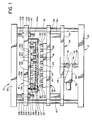
- the apparatus 10 of the present invention comprises a base support structure 12 to which are mounted a key carrying assembly 14 and a printing assembly 16.
- the key carrying assembly 14 supports a plurality of keycaps or keys 18 at predetermined key locations and in this particular embodiment also locates a printing sheet 20 above the keys 18.
- the printing assembly 16 is of particular significance in the present invention, and this functions to press certain areas of the printing sheet 20 into engagement with the top surfaces 22 and front surfaces 24 of the keys 18.
- there is provided an intermediate flexible load transfer or cushioning sheet 26 which is pressed by the printing assembly 16 into engagement with the printing sheet 20.
- the base support frame 12 comprises a stationary bottom base plate 28 and a stationary top plate 30 which are rigidly interconnected by a plurality of vertical guide posts 32 located at the corners of the plates 28 and 30.
- the key carrying assembly 14 comprises a carrying frame 34 which in turn comprises upper and lower plates 36 and 38, respectively, rigidly interconnected by vertically aligned side plates 40. These two plates 36 and 38 are provided with through openings which receive the posts 32 in a close tolerance fit so that the carrying frame 34 can move upwardly and downwardly along the posts 32 in a manner to remain accurately positioned relative to the base support structure 12.
- the vertical movement of the key carrying assembly 14 is accomplished in this particular embodiment by a wedge-like actuator 41 comprising a wedge member 42 having a lower contact surface 44 and an upper slanted contact surface 46, with these surfaces 44 and 46 engaging, respectively, a lower roller 48 mounted to the base plate 28 and an upper roller 50 mounted to the lower side of the lower plate 38 of the carrying frame 34.
- a suitable actuator (not shown for ease of illustration) moves the wedge member 42 laterally to raise or lower the carrying frame 34 and the rest of the key carrying assembly 14. It is to be understood that other mechanisms can be used to raise or lower the carrying assembly 14, and also that the key carrying assembly 14 can remain stationary while the printing assembly 16 would be vertically movable. Alternatively, both assemblies 14 and 16 could be made movable.
- the key carrying assembly 14 further comprises a carrying tray 52 which, of itself, is or may be conventional.
- This tray 52 is mounted to the top surface of the upper plate 36 and could remain fixedly attached thereto or be removable from the upper plate 36 so that trays 52 having different patterns of key locations could be used. In the event that a different pattern of key location is used, this would, of course, require a corresponding modification of the printing assembly 16.
- the tray 52 is removably placed on the plate 36, then a plurality of trays could be used, with one tray 52 being loaded with keys 18, while another tray 52 with keys 18 thereon is actually operating in the apparatus 10 to have the keys 18 imprinted.
- suitable guide means or locating means are provided to ensure that the tray 52 (and therefore the keys 18 mounted thereto) is accurately positioned.
- the tray 52 comprises a surrounding frame 54 across which extends a plate portion 56.
- a plurality of individual pedestals 58 made of a relatively rigid plastic material are fixably and accurately mounted to the plate portion 56 by screws 60 or by some other suitable means.
- Each pedestal 58 has its top and side surfaces contoured to fit within rather close tolerances the inside surfaces of a related keycap or key 18 which is mounted to that pedestal 58.
- each pedestal 58 has a horizontal top surface 62, a nearly vertical back surface 64, and a slanted front surface 66, with these surfaces 62-66 matching corresponding interior surfaces of the keys 18.
- the respective lateral surfaces 67 of the pedestals 58 and the keys 18 are likewise made in a matching configuration.
- top, front, back and lateral surfaces could be made with different slopes.
- the top pedestal surface 62 can be made with an opening 68 to receive a matching protrusion or locating member in the downwardly facing surface of the key 18.
- each locating pin 70 has an upwardly stepped configuration, having a lower cylindrical portion 72 of a larger diameter and an upper cylindrical portion 74 of a reduced diameter.
- the printing sheet 20 is provided with a plurality of locating holes 76 at spaced perimeter locations on the sheet 20, and these fit on the upper cylindrical portions 74 of the pins 70 so as to rest on the upwardly facing surfaces of the lower cylindrical pin portions 72.
- the locating holes 76 could be provided at other locations, such as having a row of locating holes 76 positioned along the center of the priting sheet 20.
- Each image area 82 has a first image area portion 84 bearing a dye material in the form of a mirror image of the image or symbol which is to be imprinted on the top surface 22 of a related key 18, and also a second image area portion 86 which bears a mirror image which is adapted to be imprinted on the front surface 24 of a related key 18.
- Each image area 82 has three sides thereof at least partially perforated along separation lines in a U-configuration, with the perforation line forming the base of the U being designated 88 and the perforation lines defining the legs of the U being designated 90.
- the perforation line 88 extends adjacent to the second image area portion 86, while the two perforation lines 90 extend along opposite lines of the image area portions 84 and 86.
- the printing assembly 16 can be considered as having a first component or subassembly 92 which provides a plurality of first contact surfaces 94 which are arranged to come into operative engagement with the top surfaces 22 of the keys 18.
- a second component or subassembly 96 having a plurality of second contact surfaces or contact surface areas 98 to come into contact with a side surface of the key 18, and in this particular arrangement come into contact with the front surfaces 24 of the keys 18.
- the second component or subassembly 96 is capable of independent movement relative to the first component or subassembly 92 in a manner that the first contact surfaces 94 are able to first come into firm operating engagement with the top of surfaces 22 in a manner to firmly press the first image area portions 84 into firm engagement with the top key surfaces 22, after which the second component or subassembly 96 brings the second contact surfaces 98 into operative engagement so that the second image area portions 86 are then brought into engagement with the front key surfaces 24. It has been found that this arrangement enables the image areas 82 to be accurately located relative to the key surfaces 22 and 24 so that the images 84′ and 86′ of each image area 82 are located within reasonably close tolerances to the key surfaces 22 and 24.
- This printing subassembly 16 is mounted to a mounting plate 100 which has a plurality of openings 102 to receive the aforementioned guide posts 32.
- the mounting plate 100 has a plurality of other through openings 104 to receive therein threaded studs 106 which extend downwardly through the mounting plate 100 and are fixedly attached to the top plate 30 of the base support structure 12.
- Each stud 106 is provided with upper and lower locating nuts 108 and 110 to enable the mounting plate 100 to be accurately positioned.
- Extending downwardly from the bottom surface of the mounting plate 100 are two vertically aligned side plates 112 which engage opposite edges of the aforementioned cushioning sheet 26, for example by means attaching bolts 113.
- This sheet 26 is approximately one-sixteenth of an inch thick and is made of a suitable rubber or elastomeric material. The sheet 26 extends over the entire array of the keys 18, and when contacted by the aforementioned contact surfaces 94 and 98 of the printing assembly 16 transmits a more uniform pressure or force against the paper image areas 82 and the key surfaces 22 and 24.
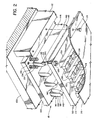
- the first component or subassembly 92 of the printing assembly 16 comprises a movable platen or plate 114 which is mounted to the aforementioned mounting plate 100 in a manner to be vertically movable relative to the plate 100. More particularly, there are a number of studs 116 (see Fig. 2) having threaded ends 118 which fit into matching sockets 120 formed in a stationary platen 122. These studs 116 also have a vertical cylindrical shank portion 124 with an expanded lower head 126, and this shank portion 124 extends through a matching opening 128 (see Fig. 5-7) in the platen or plate 114. As shown in Figs.
- each opening 128 can be provided with a bushing 130 to enable the platen 114 to move vertically along the shank portions 124 of the studs 116 toward and away from the mounting plate 100 and the platen 122.
- a number of compression springs 132 are positioned in sockets 134 at corner locations of the platen 122, and also at other locations across the face ofthe platen 122, to urge the lower movable platen 114 downwardly against the heads 126 which limit further downward movement of the platen 114.
- sockets 134a are formed in the movable platen 114 to receivethe lower ends ofthe springs 132.
- each bar 136 having a plurality of downwardly protruding contact elements 138, with each contact element 138 having a related one of the first contact sufaces 94.
- Each contact surface 94 is made with a moderate convex curve so as to match the moderate concave curvature of the top surface 22 of each key.
- the second component or subassembly 96 of the printing assembly 116 comprises the aforementioned stationary platen 122 which is removably mounted to the mounting plate 100 at a fixed location. This could be accomplished, for example, by a dovetail slide connection, three of which are shown at 140 fitting into slots 142 in the platen 122 (see Fig. 1). Fixably mounted to, and extending downwardly from, the lower surface of the stationary platen 122 are a plurality of second contact bars 144. Each of these bars 144 has a related second contact surface 98 and extends lengthwise along a location corresponding to a related row of keys 18.
- each bar 144 is, in transverse section, formed as a rounded nose portion 146, and also has an upwardly slanting surface 148 which slants upwardly in a direction away from the contact surface 98. While the stationary platen 122 is shown as being mounted directly to the plate 100, it is to be understood that an intermediate mounting plate could be attached to the plate 100 and the platen 122 attached by the dovetail connection 140-142 to this intermediate plate.
- the movable platen 114 has a plurality of elongate, slot-like through openings 150 having length and width dimensions moderately greater than corresponding length and width dimensions of related contact bars 144 so that these contact bars can extend through these openings 150.
- the aforementioned compressions springs 132 are mounted in their related sockets 134 in the stationary platen 122 and in the sockets 134a in the movable platen 114 so that the springs 132 can be compressed entirely within the sockets 134 and 134a. This permits the first lower platen 114 to move upwardly into contact with the upper stationary platen 122, and the significance of this will be discussed later in the description of the operation of the present invention.
- the carrying frame 34 of the key carrying assembly 14 is in its lower position, as shown in Fig. 1.
- a plurality of keys 18 are placed on the pedestals 58.
- the pedestals 58 are desirably mounted on a removable tray 52, and the keys 18 can be placed on these pedestals 58 at a location away from the apparatus 10, with the tray 52 then being moved into position on the upper plate 36 of the frame 34.
- the caps can be placed directly on the pedestals 58 at the location of the apparatus 10. Suitable attaching means can be provided to accurately position the tray 52 on the plate 36.
- the printing sheet 20 which matches the array of keys 18 is placed on top of the tray 52, this being accomplished by fitting the locating holes 76 of the printing sheet 20 on the matching upper protrusions 74 of the locating pints 70. As indicated previously, this accurately locates the various image areas 82 over corresponding keys 18.
- the intermediate load transfer blanket or sheet 26 is positioned between the printing assembly 16 and the printing sheet 20 by attaching the side edges of the sheet or blanket 26 to the aforementioned mounting plates 112.
- the platen 122 is heated to a suitable operating temperature (e.g., typically between 350 to 525 degrees F) so that the contact surfaces 98 are brought to the same appropriate operating temperature (e.g., between about 350 to 525 degrees F).
- a suitable operating temperature e.g., typically between 350 to 525 degrees F
- this is conveniently accomplished through electric heating, with resistance heating rods being placed through openings provided in the stationary platen 122 (or in openings in an intermediate plate between the platen 122 and the plate 100, if such an intermediate plate is provided).
- resistance heating rods are placed in the movable platen 114 and in the contact bars 136. As illustrated in Fig. 5, this is desirably accomplished by forming a circular opening 152, with one semi-circular half of this opening 152 being formed at the lower surface of the plate 114, and the other semi-circular half of this opening 152 being formed in the adjacent bar 136. Then the resistance heating element 154 is placed in this circular opening 152. It has been found that this arrangement provides an optimized heating pattern so that contact surfaces 148 can be maintained at the desired operating temperature within rather close tolerances. Further, the proximity of the bars 136 with the contact surfaces 98 also assist in maintaining these contact surfaces 98 at the proper operating temperature. It is to be understood, however, that other forms of heating could be used, and since these alternative forms are well known in the prior art, they will not be described herein.
- the carrying frame 34 is moved upwardly by means of the actuating wedge member 42.
- the carrying frame 34 has moved upwardly so that the contact surfaces 94 are just about to press the intermediate load transfer sheet 26 against the printing sheeet 20 which in turn will press against the top key surfaces 22, and the lower end nose portions 146 of the second contact bars 144 are likewise coming closer to the engagement position.
- the first contact surfaces 94 press portions of the load transfer sheet 26 against the first area portions 84 of the image areas 82 of the printing sheet 20 so that these sheet portions 84 become pressed against top key surfaces 22.
- the force which these contact surfaces 94 exert is dependent upon the strength and location of the compression springs 132. These springs 132 are arranged so that this force is sufficient so that the contact surfaces 94 press the sheet portions 84 against the top key surfaces 22 with sufficient firmness so that these sheet portions 84 remain properly located and positioned against the top key surfaces 22 through the remainder of the process while the contact surfaces 94 remain in their engaging position.
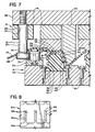
- the engagement of the keys 18 causes the movable platen 114 to move further upwardly toward the platen 122.
- the relative motion between the platen 114 and the second contact bars 144 results in the nose portions 146 of the bars 144 pushing the intermediate load transfer sheet 26 downwardly relative to the keys 18, until the contact surfaces 98 of these bars 144 act through adjacent portions of the load transfer sheet 26 to cause these to come into pressing engagement where the second image area portions 86 of the printing sheet 20 become pressed against the front key surfaces 24.
- the frictional engagement between the image portions 86 and the cushioning sheet 26 is relatively small. Then, as the nose portions 146 of the bars 144 reach their extreme lower level of travel, the cushioning sheet portions adjacent the surface portions 98 bring the sheet image portions 86 into firm engagement with the key surfaces 24. However, there is by this time little, if any, tendency for the cushioning sheet portions adjacent the image areas 86 to slide over the printing sheet portions 86 or to cause any displacement of these printing sheet image portions 86. The net effect is that the two printing sheet image portions 84 and 86 become positioned against the key surfaces 22 and 24 within very close tolerances for accurate location of the images.
- the compression springs 132 With the platen 114 in the position of Fig. 7, the compression springs 132 become totally compressed in their respective sockets 134 and 134a and the platen 114 comes into engagement with the platen 122.
- the pressure or force against the key surfaces 22 and 24 depends primarily on the force exerted by the actuating mechanism through the wedge member 42.
- the heat transmitted from the contact surfaces 94 and 98 causes the dye material forming the images 84a and 86a to sublimate, and also heats the adjacent surface areas of the keys 18.
- the dye material migrates into the upper and front surfaces 22 and 24, respectively, of the keys 18 so that these images are imprinted into the material adjacent these surfaces 22 and 24.
- the carrying frame 34 is lowered, and the printing sheet 20 is removed.
- Another set of keycaps 18 is placed on the pedestals 58, and a second printing sheet 20 is positioned over the keys 18. Then the same process is repeated in the manner described above.
- a modified form of the printing sheet 20 is illustrated in Fig. 8, where a small portion of the modified printing sheet, designated 20a, is shown in an enlarged scale. Adjacent portions of two image areas 82a are shown, with each of these image areas 82a having the before mentioned perforation lines, designated 88a and 90a, of a U-shaped configuration.
- an elongate paper strip 160 Located between each adjacent pair of side perforation lines 90a of two adjacent image areas 82a is an elongate paper strip 160.
- This strip 160 is formed with a plurality of transverse perforation lines 162 at spaced intervals along the length of the strip 160.
- These perforation lines 162 are arranged in an alternating pattern, with half of these perforation lines 162 extending from one of the perforation lines 90a, and the other half extending from the other perforation line 90a, and with each perforation line 162 overlapping adjacent perforation lines 162, but not extending all the way to the opposite line 90a.
- the image areas 82a of the printing sheet 20a break loose from the remainder of the sheet along their separation lines 88a and 90a.
- the intermediate strips 160 become stretched.
- the strip between adjacent image areas 82 simply breaks at some location along its length.
- the arrangement shown in Fig. 8 permits the strip 160 to elongate in a more predictable pattern.
- the dye material in the image areas 82 actually sublimates (goes from a solid state directly to a gaseous state) so that the dye material then migrates into the surface portions of the keys 18. It is to be understood, however, that within the broader scope of the present invention, other printing techniques could be used.
Landscapes
- Engineering & Computer Science (AREA)
- Mechanical Engineering (AREA)
- Printing Methods (AREA)
- Manufacture Of Switches (AREA)
Applications Claiming Priority (2)
| Application Number | Priority Date | Filing Date | Title |
|---|---|---|---|
| US15015688A | 1988-01-29 | 1988-01-29 | |
| US150156 | 1988-01-29 |
Publications (2)
| Publication Number | Publication Date |
|---|---|
| EP0325809A2 true EP0325809A2 (fr) | 1989-08-02 |
| EP0325809A3 EP0325809A3 (fr) | 1989-10-11 |
Family
ID=22533338
Family Applications (1)
| Application Number | Title | Priority Date | Filing Date |
|---|---|---|---|
| EP88202750A Withdrawn EP0325809A3 (fr) | 1988-01-29 | 1988-11-30 | Méthode et système d'imprimerie à diffusion multisurface |
Country Status (1)
| Country | Link |
|---|---|
| EP (1) | EP0325809A3 (fr) |
Cited By (2)
| Publication number | Priority date | Publication date | Assignee | Title |
|---|---|---|---|---|
| FR2700300A1 (fr) * | 1993-01-08 | 1994-07-13 | Claveau Jean Noel | Membrane-pré-formée pour la sublimation d'un décor sur un objet. |
| CN115848009A (zh) * | 2023-02-27 | 2023-03-28 | 泉州市云萃科技有限公司 | 一种防伪标签用的压印机 |
Family Cites Families (4)
| Publication number | Priority date | Publication date | Assignee | Title |
|---|---|---|---|---|
| GB2120169B (en) * | 1982-05-12 | 1985-10-23 | David Durand | Method of applying a dye image to a plastic member and the image bearing member thereby formed |
| US4670084A (en) * | 1983-06-20 | 1987-06-02 | David Durand | Apparatus for applying a dye image to a member |
| US4664030A (en) * | 1985-09-30 | 1987-05-12 | Advanced Input Devices, Inc. | Simultaneous multisurface diffusion printer |
| GB8614034D0 (en) * | 1986-06-10 | 1986-07-16 | Mascoprint Developments Ltd | Printing |
-
1988
- 1988-11-30 EP EP88202750A patent/EP0325809A3/fr not_active Withdrawn
Cited By (3)
| Publication number | Priority date | Publication date | Assignee | Title |
|---|---|---|---|---|
| FR2700300A1 (fr) * | 1993-01-08 | 1994-07-13 | Claveau Jean Noel | Membrane-pré-formée pour la sublimation d'un décor sur un objet. |
| EP0606189A1 (fr) * | 1993-01-08 | 1994-07-13 | Jean-Noel Claveau | Machine à membrane pré-formée pour la sublimation d'un décor sur un objet |
| CN115848009A (zh) * | 2023-02-27 | 2023-03-28 | 泉州市云萃科技有限公司 | 一种防伪标签用的压印机 |
Also Published As
| Publication number | Publication date |
|---|---|
| EP0325809A3 (fr) | 1989-10-11 |
Similar Documents
| Publication | Publication Date | Title |
|---|---|---|
| US6029966A (en) | Flexible, self conforming, workpiece support system | |
| EP2000303B1 (fr) | Machine pour la décoration de plaquettes métalliques | |
| US4151397A (en) | Self-aligning thermal print head | |
| JP6543739B2 (ja) | 立体プリンタ装置の成形作業台 | |
| JPH04226898A (ja) | プリント回路板用孔開け装置 | |
| US4792376A (en) | Apparatus for the sublimation printing of keyboard caps | |
| JPH07201252A (ja) | 圧力作動スイッチアセンブリ | |
| US5809858A (en) | Device for achieving optimum leveling of cutting die and platen components in die cutting machines | |
| JP4307342B2 (ja) | 基板支持機構、並びに該機構を利用する部品実装装置、クリーム半田印刷装置 | |
| US5983766A (en) | Steel rule cutting die with removable cutting units and method for using same | |
| US6046757A (en) | Thermal printer having thermal head unit support structure | |
| US4664030A (en) | Simultaneous multisurface diffusion printer | |
| EP0215954A1 (fr) | Procede de fabrication de produits moules en plastiques presentant des caracteres tels que lettres et symboles sur leurs surfaces superieure et frontale, et dispositif de dessin des caracteres | |
| US4861085A (en) | Pin transfer apparatus | |
| JPH03170219A (ja) | キーカッティング装置 | |
| US5461976A (en) | Power driven seal device | |
| JP4172837B2 (ja) | エキスパンド治具 | |
| US4391669A (en) | Device for making recording disc cartridge | |
| KR102129224B1 (ko) | 금속박 인쇄장치용 금형구조 | |
| EP1644164A1 (fr) | Machine destinee a marquer par poin onnage des peaux ou d'autres articles en forme de feuille | |
| JPH0655536B2 (ja) | プリンタのインクリボン案内装置 | |
| JP2004058553A (ja) | プリンタ | |
| JP2758635B2 (ja) | 通帳類印字装置 | |
| JPS6382746A (ja) | 方形成形品の転写装置 | |
| JPH082670A (ja) | 切断ワークの分離装置 |
Legal Events
| Date | Code | Title | Description |
|---|---|---|---|
| PUAI | Public reference made under article 153(3) epc to a published international application that has entered the european phase |
Free format text: ORIGINAL CODE: 0009012 |
|
| AK | Designated contracting states |
Kind code of ref document: A2 Designated state(s): AT BE CH DE ES FR GB GR IT LI LU NL SE |
|
| PUAL | Search report despatched |
Free format text: ORIGINAL CODE: 0009013 |
|
| AK | Designated contracting states |
Kind code of ref document: A3 Designated state(s): AT BE CH DE ES FR GB GR IT LI LU NL SE |
|
| STAA | Information on the status of an ep patent application or granted ep patent |
Free format text: STATUS: THE APPLICATION IS DEEMED TO BE WITHDRAWN |
|
| 18D | Application deemed to be withdrawn |
Effective date: 19900412 |