EP0325840A2 - Werkstückträger für Biegemaschinen - Google Patents
Werkstückträger für Biegemaschinen Download PDFInfo
- Publication number
- EP0325840A2 EP0325840A2 EP88310544A EP88310544A EP0325840A2 EP 0325840 A2 EP0325840 A2 EP 0325840A2 EP 88310544 A EP88310544 A EP 88310544A EP 88310544 A EP88310544 A EP 88310544A EP 0325840 A2 EP0325840 A2 EP 0325840A2
- Authority
- EP
- European Patent Office
- Prior art keywords
- workpiece
- die
- arm
- bending
- raised
- Prior art date
- Legal status (The legal status is an assumption and is not a legal conclusion. Google has not performed a legal analysis and makes no representation as to the accuracy of the status listed.)
- Granted
Links
Images


Classifications
-
- B—PERFORMING OPERATIONS; TRANSPORTING
- B21—MECHANICAL METAL-WORKING WITHOUT ESSENTIALLY REMOVING MATERIAL; PUNCHING METAL
- B21D—WORKING OR PROCESSING OF SHEET METAL OR METAL TUBES, RODS OR PROFILES WITHOUT ESSENTIALLY REMOVING MATERIAL; PUNCHING METAL
- B21D5/00—Bending sheet metal along straight lines, e.g. to form simple curves
- B21D5/02—Bending sheet metal along straight lines, e.g. to form simple curves on press brakes without making use of clamping means
- B21D5/0281—Workpiece supporting devices
Definitions
- the present invention relates to a device to support a workpiece which being bent by a bending machine such as a press brake.
- a press brake to bend heavy workpieces such as steel sheets is usually equipped with a device to support the workpiece which is raised as the processing progresses.
- the device functions to prevent the workpiece from bending at a shoulder of a die of the press brake because of the dead load as well as force of inertia, as well as to remove the workpiece from the press brake after the processing is completed.
- the device comprises typically a fundamental frame placed before a bed of the press brake.
- the frame is equipped with an arm pivotaly fixed to the frame near the bed so that its rear half, or the farther one from the bed, is directed to the die on the bed.
- the rear half of the arm supports a table by way of a guidance means, which allows the table to approach or go away from the die.
- the table is so positioned before the processing starts that its top is on the same level with that of the die.
- a raising means is provided to raise the table by means of the arm in synchronization with the processing of the workpiece by the press brake.
- the device is also equipped with a position control means which maintains the distance between the table and die throughout the processing.
- the guidance means usually comprises a pair of guide rails extending toward the die along the table top which supports the workpiece and two pairs of members to be guided by the rails, arranged at an appropriate interval between each pair.
- the members are actually sliders or rollers which slide or roll on the rails.
- the rails and members are arranged alternatively either on the bottom of the table or on the rear half of the arm. Because the guide rails extend straight, the arm and table are raised at the same angle.
- the table top can not follow up well the workpiece, particularly at the beginning of the processing, because the rise of the table is controlled in synchronization with descent of the punch or of the portion of the workpiece between the ridges. As a result, plastic deformation may be caused, at the ridges of the die for instance, or the workpiece curved apart the table may vibrate which causes the point of the workpiece where the punch should be applied to displace.
- a front portion of the guide rails that is near the die, swells downwards convexly.
- the members running on the rails reach the swelling portion and push up the front end of the table as they advance further along the portion.
- the angle by which the table is raised is made smaller than that by which the arm is raised over a predetermined range of the latter angle at the early stages of the processing, which allows the table to follow the workpiece well even when the workpiece curves convexly, swelling upwards. The plastic deformation as well as vibration of the workpiece can be prevented as a result.
- the displacement of the table front in connection with the arm can be controlled in correspondence with the rise of the arm.
- the angle by which the table is raised for instance, can be made larger than that by which the arm is raised when the arm rises highest, which permits the arm raising means to be of a smaller size.
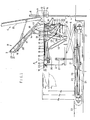
- the workpiece-supporting device of the present invention comprises a fundamental frame 2 placed in front of a press break 1.
- a table 3 having a plane top is supported by the frame 2.
- the Frame 2 and table 3 can be shifted toward or away from the press brake by means of a shifting means 7.
- the frame 2 and table 3 are positioned in the rear, or farthest from the press brake, as illustrated in Figures 3 and 9, to mount a workpiece W such as a steel plate onto the table at a predetermined position from a conveyor not illustrated in the drawings or return the workpiece from the table to the conveyor.
- a workpiece W such as a steel plate
- they are positioned in the front or nearest the press brake as illustrated in Figures 4-7 while the workpiece is processed.
- the point of the workpiece to which the punch of the press brake is to be applied is located vertically above the center line of a groove 11 which is cut on the top of a die 5.
- the shifting means 7 comprises an air cylinder 24 and a guidance means 25 as illustrated in Figure 1.
- the air cylinder 24 is fixed at one end in a pit 23 and connected at the other to a lifting means 6, which carries the frame 2 and table 3.
- the forward and backward movement of the lifting means carrying the frame and table is guided by the guidance means 25, which further comprises a pair of parallel guide rails 26 and two pairs of guide rollers 27.
- the guide rails 26, which is made of channel steel, extend in the pit 23 toward the press break.
- the other structure of the shifting means 7 than described above is also applicable as far as the frame 2 and table 3 can be carried to and fro between the front and rear positions.
- the lifting means 6 comprises a table lifter which further comprises pairs of bars each consisting of two bars crossing each other as illustrated in Figure 1.
- the structure enables the frame and table to be lifted and lowered very accurately.
- the lifting means 6 is so constructed that it can lift and lower the table 3 at least between a standard position HO and a high position Hh as illustrated in Figure 1.
- the table 3 is positioned at the standard position HO while the workpiece is processed, where the bottom of the workpiece W mounted on the table is in touch with the top of the die 5. After the processing finishes, the table is lifted to the high position Hh to lift the workpiece W off the processing groove 11.
- the other structure than described above is also applicable as long as it can lift and lower the table 3 at least between the standard and high positions HO and Hh.
- the lifting means 6 is so constructed that it can lower the table 3 to a low position Hl as illustrated in Figure 1.
- the table 3 is lowered from the high position Hh to the low position Hl while being withdrawn to the rear.
- the workpiece is thus able to pass obliquely between the punch 9 and die 5.
- Figures 7 and 8 illustrate such oblique lowering of the workpiece.
- the table 3 at the standard position HO is is raised by a raising means 10 to support the portion of the workpiece which is raised on a ridge 12 of the die 5 as the punch 9 descends and the processing progresses.
- the table 3 is raised from a horizontal position A to an inclined position B as indicated in Figures 1 and 2 in synchronization with the processing.
- the workpiece is raised at about 45 ° at the inclined position B.
- the punch 9 is lifted off the workpiece after the processing finishes.
- the table 3 is then shifted to the rear by the shifting means 7 and returned to the horizontal position by the raising means 10.
- the distance between the table 3 and ridge 12 is maintained by a position control means 13 throughout the raising and lowering of the table.
- the raising means 10 comprises an air cylinder 28 to raise the table 3 by way of the arm 14 and a supporting spring 29 to support the weight of the arm, table and workpiece at early stages of the processing.
- the supporting spring 29 is provided to nullify the load onto the air cylinder 28 at the beginning of the processing as well as to absorb any shock which occurs when the table returns to the horizontal position after the processing is completed. Additionally, a cushion is separated inside the cylinder 28, though not illustrated in the drawings, wherein pressure increases as the cylinder extends. The extension of the cylinder 28 is thus stopped very smoothly when the table reaches the inclined position.
- any other structure is applicable to the raising means 10 as long as the arm 14 is able to be raised and lowered around a fulcrum shaft 35 to raise and lower the table 3 between the inclined and horizontal positions.
- the arm 14 is so incorporated in the system that its rear half, or the farther one from the die 5, is always directed toward the die throughout the processing.
- the table 3 supported by the rear half is able to move to and fro along the rear half while being guided by a guidance means.
- the position control means 13 comprises a pair of parallel position control boards 31, a pair of position control pins 32 and, preferably, a supporting means 33.
- the parallel boards 31 are fixed under the table 3 with an appropriate distance between each other. They have congruent position control grooves 30 opened therein respectively. Each of the grooves 30 is an arc of which center is the ridge 12.
- the position control pins 32 are fixed on the sides of the fundamental frame 2 to be inserted movably in the grooves 30.
- the distance between the table 3 and ridge 12 is maintained irrespective of the angle ⁇ , by which the table is raised, by the position control means 13 which pushes the table away from the ridge as the table is raised. Any other structure of the position control means 13 is applicable as long as it can maintain the distance between the table and ridge throughout the operation.
- the supporting means 33 is preferably included in the position control means 13, which comprises a link lever 34 and coil spring 36.
- the top end of the link lever 34 is connected to the front of the table 3, slidably in the vertical direction to the table top, while the middle of the lever is connected to the arm 14 with a pivot as illustrated in Figure 1.
- the coil spring 36 on the other hand connects between the bottom end of the link lever 34 and the fulcrum shaft 35.
- the supporting means 33 is provided to share the weight so that the pins 32 and boards 31 can be of a smaller size.
- the supporting means is, however, not indispensable to the present invention. Even when it is added to the system, the structure is not restricted to the above-described one.
- the guidance means 15 comprises a pair of guide rails 16 and two pairs of guide rollers 17.
- the guide rails 16 are fixed under the table 3.
- the guide rollers 17 are attached to both the sides of the rear half of the arm 14 with an appropriate distance between the pairs so that they can roll on the rails 16.
- the table 3 is pushed away from the ridge 12 by the position control means 13 as the arm 14 is raised while being guided by the guidance means 15.
- a raising control means 18 is provided on the rails 16, nearer to the bed than the guide rollers 17 at the beginning of the processing, which curves convexly, swelling downwards.
- a number of fixing devices 19 are provided on the table top at appropriate intervals to fix the workpiece W on the table 3 while the workpiece is taken away from the press brake.
- the follow-up surface 20 which is in contact with the workpiece is determined by the tops of the fixing means 19, the follow-up surface 20 is illustrated in Figure 2 as coinciding with the table top for the sake of simplicity of the drawing.
- fixing devices such as electric magnets or vacuum absorbtion devices
- the vacuum absorbtion devices are preferred in the present embodiment because they can fix the workpiece irrespective of its intensity of magnetism.
- the fixing devices 19 functions while, after the processing has been completed, the punch is lifted off the workpiece, the workpiece is lifted off the die and withdrawn out of the press break, and the table returns to the rear horizontal position.
- the table 3 is divided into a middle table 21 and a pair of side tables 22 at both sides of the middle table.
- the middle and side tables are linked by means of a pivot and the bottoms of the middle and side tables are connected by a pair of second air cylinders.
- the side tables 22 can be raised to a standing position C as illustrarted in Figure 1 by extending the air cylinders after the table 3 reaches the inclined position B.
- the fixing devices 19 are provided on the side tables 22 so that the workpiece can be fixed between the inclined and standing positions B and C.
- the side tables 22 are equiped, though not illustrated in the drawings, on their tops with ball or roller bearings to facilitate the mounting of the workpiece onto the table 3 as well as removing thereof from the table.
- a supporting spring 37 is therefore provided connecting the frame 2 with the base of the lifting means 6 to prevent the rear portion of the frame 2 from being raised.
- Plate bending work is achieved as follows by the press break equipped with the follow-up supporting device of the present invention, under the control of a program incorporated in the sytem, or following instructions provided by the operator to the system:
- the fundamental frame 2 is positioned in the rear while the table 3 is laid horizontally at the high position Hh so that a workpiece W is mounted thereon a a predetermined position with a conveyor not illustrated.
- the frame 2 is then shifted to the front position as illustrated in Figure 4 by extending the air cylinder 4 of the driving means 7, where the point of the workpiece to which the punch should be applied is positioned vertically above the center line of the groove 11.
- the table 3 is then descended to the standard position HO and the setting of the workpiece W in the press brake 1 is completed.
- the ram 8 starts descending and the table 3 starts being raised when the punch 9 gets in touch with the workpiece W.
- the air cylinder 28 starts extension with no considerable mechanical resistance when pressure air starts being supplied to the air cylinder.
- the supporting spring 29 also extends and the weight of the arm, table and workpiece gradually becomes shared by the air cylinder 28.
- pressure increases in the cushion cylinder of the cylinder 28 by degrees as the cylinder extends. The extension speed of the air cylinder 28 is thus the largest at the beginning of the extension and diminishes as the extension progresses.
- the front pairs of the guide rollers 17 advancing along the raising control means 18 pushes upwards the front end of the table at the early stages and thereby makes the rising angle ⁇ of the table smaller than the rising angle ⁇ of the arm, as pointed to by an arrow B′ in Figure 2.
- the displacement of the table front is removed by degrees as the raising continues.
- the table 3 is in the inclined position as illustrated in Figure 6 when the punch 9 has pressed down the workpiece W to the bottom of the groove 11 and the processing has finished.
- the ram 8 and punch 9 are lifted after the workpiece is fixed on the table by the fixing means 19.
- the table 3 is then lifted to the high position Hh with the lifting means 6 to separate the bent workpiece from the die 5 as illustrated in Figure 7.
- the workpiece is then withdrawn from the press brake 1 by contracting the air cylinder 24 of the driving means 7 and returning the frame 2 and table 3 to the rear, before or after the table is again laid horizontally.
- the workpiece When the front end of the bent workpiece may get in touch with the lifted punch if shifted horizontally, for instance when the workpiece has been bent so deep or protrudes so far from the press brake, the workpiece can pass obliquely between the punch 9 and die 5 by achieving the horizontal shift of the table to the rear simultaneously with lowering of the same to the low position Hl.
- the table 3 In this case the table 3 is laid horizontally only after the withdrawl to the rear has been completed.
- the table 3 can be returned to the horizontal state also smoothly because the supporting spring 29 absorbs the shock, which prevents the workpiece from rebounding and displacing on the table.
- the table 3 is again lifted to the standard position HO with the lifting means 6 and the bent workpiece is transferred onto a conveyor, which carries the workpiece away, and one cycle of the processing is completed.
- the way of the processing is not restricted to the one described above.
- the table 3 may not be lifted to the high position Hh but returned from the inclined position B to the horizontal position A simultaneously with lifting of the punch 9 before shifted to the rear.
- the order of withdrawl to the rear, lowering to the horizontal state and lifting to the high position is exchangeable with each other or can be performed simultaneously.
- the table positions where the workpiece is mounted onto and removed from the table can be determined freely and can be different from each other.
Landscapes
- Engineering & Computer Science (AREA)
- Mechanical Engineering (AREA)
- Bending Of Plates, Rods, And Pipes (AREA)
Applications Claiming Priority (2)
| Application Number | Priority Date | Filing Date | Title |
|---|---|---|---|
| JP1995088A JPH01197012A (ja) | 1988-01-29 | 1988-01-29 | 突曲げ加工用加工物追従支持装置 |
| JP19950/88 | 1988-01-29 |
Publications (3)
| Publication Number | Publication Date |
|---|---|
| EP0325840A2 true EP0325840A2 (de) | 1989-08-02 |
| EP0325840A3 EP0325840A3 (en) | 1990-08-16 |
| EP0325840B1 EP0325840B1 (de) | 1994-01-05 |
Family
ID=12013484
Family Applications (1)
| Application Number | Title | Priority Date | Filing Date |
|---|---|---|---|
| EP19880310544 Expired - Lifetime EP0325840B1 (de) | 1988-01-29 | 1988-11-09 | Werkstückträger für Biegemaschinen |
Country Status (3)
| Country | Link |
|---|---|
| EP (1) | EP0325840B1 (de) |
| JP (1) | JPH01197012A (de) |
| DE (1) | DE3886917T2 (de) |
Cited By (7)
| Publication number | Priority date | Publication date | Assignee | Title |
|---|---|---|---|---|
| EP0619151A1 (de) * | 1993-04-06 | 1994-10-12 | Beyeler Raskin S.A. | Vorrichtung zum Manipulieren eines Werkstücks während aufeinanderfolgenden Biegeoperationen in einer Presse |
| CN109047542A (zh) * | 2018-08-16 | 2018-12-21 | 深圳懒人自动化机械有限公司 | 一种折弯随动托料装置 |
| CN110170550A (zh) * | 2019-06-15 | 2019-08-27 | 深圳懒人自动化机械有限公司 | 一种智能折弯重载随动托料车 |
| CN110722026A (zh) * | 2019-10-26 | 2020-01-24 | 台州弘锐精密机械有限公司 | 一种薄铝板折压加工一体机 |
| CN114011912A (zh) * | 2021-09-17 | 2022-02-08 | 中铁十六局集团电气化工程有限公司 | 一种幕墙铝板加工用折弯机 |
| CN116408371A (zh) * | 2023-04-17 | 2023-07-11 | 合肥中庆机械科技有限公司 | 一种冷柜柜体多角度折弯机 |
| KR102560976B1 (ko) * | 2023-01-26 | 2023-07-28 | 최상태 | 절곡기용 보조 서포터 |
Families Citing this family (3)
| Publication number | Priority date | Publication date | Assignee | Title |
|---|---|---|---|---|
| DE10357156B4 (de) * | 2003-12-06 | 2014-09-18 | Bayerische Motoren Werke Aktiengesellschaft | Rohrbiegeanlage |
| WO2012019220A1 (en) * | 2010-08-13 | 2012-02-16 | Paul Robert Mccleary | A sheet support assembly |
| WO2018148917A1 (zh) * | 2017-02-17 | 2018-08-23 | 苏州科爱佳自动化科技有限公司 | 航天级球栅检测系统 |
Family Cites Families (2)
| Publication number | Priority date | Publication date | Assignee | Title |
|---|---|---|---|---|
| US3715907A (en) * | 1969-10-29 | 1973-02-13 | Amada Co Ltd | Apparatus for supporting sheet materials in bending presses |
| FR2111852B1 (de) * | 1970-10-27 | 1974-03-29 | Amada Co Ltd |
-
1988
- 1988-01-29 JP JP1995088A patent/JPH01197012A/ja active Pending
- 1988-11-09 EP EP19880310544 patent/EP0325840B1/de not_active Expired - Lifetime
- 1988-11-09 DE DE19883886917 patent/DE3886917T2/de not_active Expired - Fee Related
Cited By (10)
| Publication number | Priority date | Publication date | Assignee | Title |
|---|---|---|---|---|
| EP0619151A1 (de) * | 1993-04-06 | 1994-10-12 | Beyeler Raskin S.A. | Vorrichtung zum Manipulieren eines Werkstücks während aufeinanderfolgenden Biegeoperationen in einer Presse |
| CN109047542A (zh) * | 2018-08-16 | 2018-12-21 | 深圳懒人自动化机械有限公司 | 一种折弯随动托料装置 |
| CN109047542B (zh) * | 2018-08-16 | 2024-04-19 | 深圳懒人自动化机械有限公司 | 一种折弯随动托料装置 |
| CN110170550A (zh) * | 2019-06-15 | 2019-08-27 | 深圳懒人自动化机械有限公司 | 一种智能折弯重载随动托料车 |
| CN110722026A (zh) * | 2019-10-26 | 2020-01-24 | 台州弘锐精密机械有限公司 | 一种薄铝板折压加工一体机 |
| CN110722026B (zh) * | 2019-10-26 | 2020-06-09 | 安徽坤源铝业有限公司 | 一种薄铝板折压加工一体机 |
| CN114011912A (zh) * | 2021-09-17 | 2022-02-08 | 中铁十六局集团电气化工程有限公司 | 一种幕墙铝板加工用折弯机 |
| CN114011912B (zh) * | 2021-09-17 | 2023-12-15 | 中铁十六局集团电气化工程有限公司 | 一种幕墙铝板加工用折弯机 |
| KR102560976B1 (ko) * | 2023-01-26 | 2023-07-28 | 최상태 | 절곡기용 보조 서포터 |
| CN116408371A (zh) * | 2023-04-17 | 2023-07-11 | 合肥中庆机械科技有限公司 | 一种冷柜柜体多角度折弯机 |
Also Published As
| Publication number | Publication date |
|---|---|
| EP0325840B1 (de) | 1994-01-05 |
| EP0325840A3 (en) | 1990-08-16 |
| DE3886917D1 (de) | 1994-02-17 |
| JPH01197012A (ja) | 1989-08-08 |
| DE3886917T2 (de) | 1994-05-05 |
Similar Documents
| Publication | Publication Date | Title |
|---|---|---|
| US6546609B1 (en) | Automatic riveting apparatus | |
| CN111496118A (zh) | 一种自动上下料冲床设备及其成型方法 | |
| CN101396715A (zh) | 双向移动立式钢筋自动弯曲机 | |
| EP0325840B1 (de) | Werkstückträger für Biegemaschinen | |
| CN107350378B (zh) | 一种冷柜内胆z形底板生产线 | |
| EP0325841B1 (de) | Stossabsorbierender Werkstückträger für Biegemaschinen | |
| KR20200129287A (ko) | 샤링기용 클램핑장치 | |
| CN108906978A (zh) | 一种高性能可调节倾度的压力机及工作方法 | |
| CN220739195U (zh) | 一种农机轮毂冲孔上料机构 | |
| CN110788358B (zh) | 多轴对立钻床 | |
| CN220837585U (zh) | 一种冰箱钣金件自动铆压机 | |
| KR100212592B1 (ko) | 프레스 가공기 | |
| CN212264926U (zh) | 激光切管机自动送料装置 | |
| GB2104822A (en) | A method of and an apparatus for controlling a machine tool | |
| CN208932454U (zh) | 一种具有预调功能的装载台 | |
| CN224222555U (zh) | 一种可调节式汽车零件校直机 | |
| CN219944397U (zh) | 一种冲压下料装置 | |
| JPH0824964B2 (ja) | 折曲げ機のバックゲージ装置 | |
| CN112895581A (zh) | 开式固定台压力机 | |
| JPH01181919A (ja) | 突曲げ加工用加工物追従支持装置 | |
| CN218802640U (zh) | 冲孔切边机 | |
| CN220077816U (zh) | 一种制瓦机上料装置 | |
| JPH11188437A (ja) | 搬送絞り装置 | |
| CN214568553U (zh) | 一种辘骨工件移动装置 | |
| CN218925782U (zh) | 一种金属板件冲压装置 |
Legal Events
| Date | Code | Title | Description |
|---|---|---|---|
| PUAI | Public reference made under article 153(3) epc to a published international application that has entered the european phase |
Free format text: ORIGINAL CODE: 0009012 |
|
| AK | Designated contracting states |
Kind code of ref document: A2 Designated state(s): DE FR GB IT |
|
| PUAL | Search report despatched |
Free format text: ORIGINAL CODE: 0009013 |
|
| AK | Designated contracting states |
Kind code of ref document: A3 Designated state(s): DE FR GB IT |
|
| 17P | Request for examination filed |
Effective date: 19910208 |
|
| 17Q | First examination report despatched |
Effective date: 19920318 |
|
| GRAA | (expected) grant |
Free format text: ORIGINAL CODE: 0009210 |
|
| ITF | It: translation for a ep patent filed | ||
| AK | Designated contracting states |
Kind code of ref document: B1 Designated state(s): DE FR GB IT |
|
| REF | Corresponds to: |
Ref document number: 3886917 Country of ref document: DE Date of ref document: 19940217 |
|
| ET | Fr: translation filed | ||
| PGFP | Annual fee paid to national office [announced via postgrant information from national office to epo] |
Ref country code: GB Payment date: 19941104 Year of fee payment: 7 |
|
| PLBE | No opposition filed within time limit |
Free format text: ORIGINAL CODE: 0009261 |
|
| STAA | Information on the status of an ep patent application or granted ep patent |
Free format text: STATUS: NO OPPOSITION FILED WITHIN TIME LIMIT |
|
| 26N | No opposition filed | ||
| PG25 | Lapsed in a contracting state [announced via postgrant information from national office to epo] |
Ref country code: FR Effective date: 19950731 |
|
| PG25 | Lapsed in a contracting state [announced via postgrant information from national office to epo] |
Ref country code: DE Effective date: 19950801 |
|
| REG | Reference to a national code |
Ref country code: FR Ref legal event code: ST |
|
| PG25 | Lapsed in a contracting state [announced via postgrant information from national office to epo] |
Ref country code: GB Effective date: 19951109 |
|
| GBPC | Gb: european patent ceased through non-payment of renewal fee |
Effective date: 19951109 |
|
| PG25 | Lapsed in a contracting state [announced via postgrant information from national office to epo] |
Ref country code: IT Free format text: LAPSE BECAUSE OF NON-PAYMENT OF DUE FEES;WARNING: LAPSES OF ITALIAN PATENTS WITH EFFECTIVE DATE BEFORE 2007 MAY HAVE OCCURRED AT ANY TIME BEFORE 2007. THE CORRECT EFFECTIVE DATE MAY BE DIFFERENT FROM THE ONE RECORDED. Effective date: 20051109 |