EP0325844B1 - Evaporateur avec collection du condensat - Google Patents
Evaporateur avec collection du condensat Download PDFInfo
- Publication number
- EP0325844B1 EP0325844B1 EP88310955A EP88310955A EP0325844B1 EP 0325844 B1 EP0325844 B1 EP 0325844B1 EP 88310955 A EP88310955 A EP 88310955A EP 88310955 A EP88310955 A EP 88310955A EP 0325844 B1 EP0325844 B1 EP 0325844B1
- Authority
- EP
- European Patent Office
- Prior art keywords
- tubes
- evaporator
- header
- rows
- flattened
- Prior art date
- Legal status (The legal status is an assumption and is not a legal conclusion. Google has not performed a legal analysis and makes no representation as to the accuracy of the status listed.)
- Expired - Lifetime
Links
- WYTGDNHDOZPMIW-RCBQFDQVSA-N alstonine Natural products C1=CC2=C3C=CC=CC3=NC2=C2N1C[C@H]1[C@H](C)OC=C(C(=O)OC)[C@H]1C2 WYTGDNHDOZPMIW-RCBQFDQVSA-N 0.000 claims description 24
- 238000001125 extrusion Methods 0.000 claims description 19
- 239000012530 fluid Substances 0.000 claims description 15
- 238000004891 communication Methods 0.000 claims description 14
- 238000007789 sealing Methods 0.000 claims description 12
- 239000002184 metal Substances 0.000 claims description 3
- 238000005057 refrigeration Methods 0.000 claims description 2
- 239000003507 refrigerant Substances 0.000 description 7
- 238000004378 air conditioning Methods 0.000 description 3
- 230000001143 conditioned effect Effects 0.000 description 3
- 238000010276 construction Methods 0.000 description 3
- 238000001816 cooling Methods 0.000 description 3
- 230000005484 gravity Effects 0.000 description 3
- XLYOFNOQVPJJNP-UHFFFAOYSA-N water Substances O XLYOFNOQVPJJNP-UHFFFAOYSA-N 0.000 description 3
- 238000004519 manufacturing process Methods 0.000 description 2
- 230000015572 biosynthetic process Effects 0.000 description 1
- 239000003638 chemical reducing agent Substances 0.000 description 1
- 230000006835 compression Effects 0.000 description 1
- 238000007906 compression Methods 0.000 description 1
- 230000009977 dual effect Effects 0.000 description 1
- 239000000446 fuel Substances 0.000 description 1
- 230000002452 interceptive effect Effects 0.000 description 1
- 239000000463 material Substances 0.000 description 1
- 238000000034 method Methods 0.000 description 1
- 238000009834 vaporization Methods 0.000 description 1
- 230000008016 vaporization Effects 0.000 description 1
Images


Classifications
-
- F—MECHANICAL ENGINEERING; LIGHTING; HEATING; WEAPONS; BLASTING
- F28—HEAT EXCHANGE IN GENERAL
- F28F—DETAILS OF HEAT-EXCHANGE AND HEAT-TRANSFER APPARATUS, OF GENERAL APPLICATION
- F28F1/00—Tubular elements; Assemblies of tubular elements
- F28F1/10—Tubular elements and assemblies thereof with means for increasing heat-transfer area, e.g. with fins, with projections, with recesses
- F28F1/12—Tubular elements and assemblies thereof with means for increasing heat-transfer area, e.g. with fins, with projections, with recesses the means being only outside the tubular element
- F28F1/126—Tubular elements and assemblies thereof with means for increasing heat-transfer area, e.g. with fins, with projections, with recesses the means being only outside the tubular element consisting of zig-zag shaped fins
-
- F—MECHANICAL ENGINEERING; LIGHTING; HEATING; WEAPONS; BLASTING
- F25—REFRIGERATION OR COOLING; COMBINED HEATING AND REFRIGERATION SYSTEMS; HEAT PUMP SYSTEMS; MANUFACTURE OR STORAGE OF ICE; LIQUEFACTION SOLIDIFICATION OF GASES
- F25B—REFRIGERATION MACHINES, PLANTS OR SYSTEMS; COMBINED HEATING AND REFRIGERATION SYSTEMS; HEAT PUMP SYSTEMS
- F25B39/00—Evaporators; Condensers
- F25B39/02—Evaporators
-
- F—MECHANICAL ENGINEERING; LIGHTING; HEATING; WEAPONS; BLASTING
- F25—REFRIGERATION OR COOLING; COMBINED HEATING AND REFRIGERATION SYSTEMS; HEAT PUMP SYSTEMS; MANUFACTURE OR STORAGE OF ICE; LIQUEFACTION SOLIDIFICATION OF GASES
- F25D—REFRIGERATORS; COLD ROOMS; ICE-BOXES; COOLING OR FREEZING APPARATUS NOT OTHERWISE PROVIDED FOR
- F25D21/00—Defrosting; Preventing frosting; Removing condensed or defrost water
- F25D21/14—Collecting or removing condensed and defrost water; Drip trays
-
- F—MECHANICAL ENGINEERING; LIGHTING; HEATING; WEAPONS; BLASTING
- F28—HEAT EXCHANGE IN GENERAL
- F28B—STEAM OR VAPOUR CONDENSERS
- F28B9/00—Auxiliary systems, arrangements, or devices
- F28B9/08—Auxiliary systems, arrangements, or devices for collecting and removing condensate
-
- F—MECHANICAL ENGINEERING; LIGHTING; HEATING; WEAPONS; BLASTING
- F28—HEAT EXCHANGE IN GENERAL
- F28D—HEAT-EXCHANGE APPARATUS, NOT PROVIDED FOR IN ANOTHER SUBCLASS, IN WHICH THE HEAT-EXCHANGE MEDIA DO NOT COME INTO DIRECT CONTACT
- F28D1/00—Heat-exchange apparatus having stationary conduit assemblies for one heat-exchange medium only, the media being in contact with different sides of the conduit wall, in which the other heat-exchange medium is a large body of fluid, e.g. domestic or motor car radiators
- F28D1/02—Heat-exchange apparatus having stationary conduit assemblies for one heat-exchange medium only, the media being in contact with different sides of the conduit wall, in which the other heat-exchange medium is a large body of fluid, e.g. domestic or motor car radiators with heat-exchange conduits immersed in the body of fluid
- F28D1/04—Heat-exchange apparatus having stationary conduit assemblies for one heat-exchange medium only, the media being in contact with different sides of the conduit wall, in which the other heat-exchange medium is a large body of fluid, e.g. domestic or motor car radiators with heat-exchange conduits immersed in the body of fluid with tubular conduits
- F28D1/053—Heat-exchange apparatus having stationary conduit assemblies for one heat-exchange medium only, the media being in contact with different sides of the conduit wall, in which the other heat-exchange medium is a large body of fluid, e.g. domestic or motor car radiators with heat-exchange conduits immersed in the body of fluid with tubular conduits the conduits being straight
- F28D1/0535—Heat-exchange apparatus having stationary conduit assemblies for one heat-exchange medium only, the media being in contact with different sides of the conduit wall, in which the other heat-exchange medium is a large body of fluid, e.g. domestic or motor car radiators with heat-exchange conduits immersed in the body of fluid with tubular conduits the conduits being straight the conduits having a non-circular cross-section
-
- F—MECHANICAL ENGINEERING; LIGHTING; HEATING; WEAPONS; BLASTING
- F28—HEAT EXCHANGE IN GENERAL
- F28F—DETAILS OF HEAT-EXCHANGE AND HEAT-TRANSFER APPARATUS, OF GENERAL APPLICATION
- F28F13/00—Arrangements for modifying heat-transfer, e.g. increasing, decreasing
- F28F13/04—Arrangements for modifying heat-transfer, e.g. increasing, decreasing by preventing the formation of continuous films of condensate on heat-exchange surfaces, e.g. by promoting droplet formation
-
- F—MECHANICAL ENGINEERING; LIGHTING; HEATING; WEAPONS; BLASTING
- F28—HEAT EXCHANGE IN GENERAL
- F28F—DETAILS OF HEAT-EXCHANGE AND HEAT-TRANSFER APPARATUS, OF GENERAL APPLICATION
- F28F17/00—Removing ice or water from heat-exchange apparatus
- F28F17/005—Means for draining condensates from heat exchangers, e.g. from evaporators
-
- F—MECHANICAL ENGINEERING; LIGHTING; HEATING; WEAPONS; BLASTING
- F28—HEAT EXCHANGE IN GENERAL
- F28F—DETAILS OF HEAT-EXCHANGE AND HEAT-TRANSFER APPARATUS, OF GENERAL APPLICATION
- F28F9/00—Casings; Header boxes; Auxiliary supports for elements; Auxiliary members within casings
- F28F9/02—Header boxes; End plates
- F28F9/0202—Header boxes having their inner space divided by partitions
- F28F9/0204—Header boxes having their inner space divided by partitions for elongated header box, e.g. with transversal and longitudinal partitions
- F28F9/0214—Header boxes having their inner space divided by partitions for elongated header box, e.g. with transversal and longitudinal partitions having only longitudinal partitions
-
- F—MECHANICAL ENGINEERING; LIGHTING; HEATING; WEAPONS; BLASTING
- F28—HEAT EXCHANGE IN GENERAL
- F28F—DETAILS OF HEAT-EXCHANGE AND HEAT-TRANSFER APPARATUS, OF GENERAL APPLICATION
- F28F9/00—Casings; Header boxes; Auxiliary supports for elements; Auxiliary members within casings
- F28F9/02—Header boxes; End plates
- F28F9/0243—Header boxes having a circular cross-section
-
- F—MECHANICAL ENGINEERING; LIGHTING; HEATING; WEAPONS; BLASTING
- F28—HEAT EXCHANGE IN GENERAL
- F28F—DETAILS OF HEAT-EXCHANGE AND HEAT-TRANSFER APPARATUS, OF GENERAL APPLICATION
- F28F9/00—Casings; Header boxes; Auxiliary supports for elements; Auxiliary members within casings
- F28F9/02—Header boxes; End plates
- F28F9/026—Header boxes; End plates with static flow control means, e.g. with means for uniformly distributing heat exchange media into conduits
- F28F9/027—Header boxes; End plates with static flow control means, e.g. with means for uniformly distributing heat exchange media into conduits in the form of distribution pipes
- F28F9/0273—Header boxes; End plates with static flow control means, e.g. with means for uniformly distributing heat exchange media into conduits in the form of distribution pipes with multiple holes
-
- F—MECHANICAL ENGINEERING; LIGHTING; HEATING; WEAPONS; BLASTING
- F28—HEAT EXCHANGE IN GENERAL
- F28F—DETAILS OF HEAT-EXCHANGE AND HEAT-TRANSFER APPARATUS, OF GENERAL APPLICATION
- F28F9/00—Casings; Header boxes; Auxiliary supports for elements; Auxiliary members within casings
- F28F9/02—Header boxes; End plates
- F28F9/026—Header boxes; End plates with static flow control means, e.g. with means for uniformly distributing heat exchange media into conduits
- F28F9/027—Header boxes; End plates with static flow control means, e.g. with means for uniformly distributing heat exchange media into conduits in the form of distribution pipes
- F28F9/0275—Header boxes; End plates with static flow control means, e.g. with means for uniformly distributing heat exchange media into conduits in the form of distribution pipes with multiple branch pipes
-
- F—MECHANICAL ENGINEERING; LIGHTING; HEATING; WEAPONS; BLASTING
- F28—HEAT EXCHANGE IN GENERAL
- F28D—HEAT-EXCHANGE APPARATUS, NOT PROVIDED FOR IN ANOTHER SUBCLASS, IN WHICH THE HEAT-EXCHANGE MEDIA DO NOT COME INTO DIRECT CONTACT
- F28D21/00—Heat-exchange apparatus not covered by any of the groups F28D1/00 - F28D20/00
- F28D2021/0019—Other heat exchangers for particular applications; Heat exchange systems not otherwise provided for
- F28D2021/0068—Other heat exchangers for particular applications; Heat exchange systems not otherwise provided for for refrigerant cycles
- F28D2021/0071—Evaporators
Definitions
- This invention relates to an evaporator according to the first part of claim 1.
- Such an evaporator is disclosed in document US-A-2878655.
- evaporators as a means of cooling the air to be conditioned.
- a refrigerant is flowed through an evaporator and expanded therein. In so doing, it absorbs its heat of vaporization, thereby cooling the medium with which it is in contact, typically heat exchanger tubes.
- the air to be conditioned is flowed over those tubes (which typically will be provided with fins for improved heat transfer).
- the air at least locally, will be cooled below its dew point with the result that water will condense out of the air on the fins and on the tubes. This condensate must be removed or else it will freeze and plug the air flow path.
- relatively high velocity air streams may be present as, for example, in vehicular air conditioning systems where fans operate at high speed to achieve maximum cooling in a short period of time
- the present invention is directed to obtaining the above objects.
- an evaporator for a refrigeration system comprising: a plurality of rows of upwardly extending evayorator tubes, and fins extending between the evaporator tubes of the same row to assist in heat transfer to the evaporator tubes, characterized in that the evaporator tubes of each row are connected at the lower ends thereof to a header tube common to that row along the length of the header tube; the header tubes are non-rectangular in transverse cross-section and are held together in abutting sealing engagement with each other; and the upwardly facing external surfaces of the header tubes define at least one open condensate channel for receiving and directing away condensate running down the external surfaces of the evaporator tubes.
- the means providing sealing engagement between the header tubes also holds the header tubes in assembled relation.
- the sealing means may be a bonding means, preferably a braze metal.
- the evaporator includes a manifold which interconnects the header tubes, the manifold including a tube extending through the plurality of abutting header tubes in generally transverse relation thereto and being sealed thereto, the manifold tube including apertures in its side walls in fluid communication with the interior of at least some of the abutting header tubes.
- the plurality of abutting header tubes, the sealing means and the holding means are all defined by a single extrusion.
- the evaporator tubes are flattened tubes and each of the rows is slightly spaced from adjacent others of the rows with corresponding tubes in each row aligned with the corresponding tubes in the other rows.
- each header tube and the associated evaporator tubes forms a module; the evaporator tubes, in the direction transversely of the header tube, have a lesser dimension than the header tube; the modules are stacked and assembled together with the header tubes in sealing abutment; and the fins are serpentine fins extending between adjacent evaporator tubes in each module.
- the serpentine fins may be individual to each module, or the sets of serpentine fins may additionally extend between the plurality of modules.
- the header tubes are of generally circular cross-section, and at least some of the evaporator tubes may be defined by an extrusion with the spaces between the rows thereof being defined by concave areas in the extrusion.
- the evaporator comprises a plurality of rows of upwardly extending evaporator tubes, and fins extending between the evaporator tubes of the same row to assist in heat transfer to the evaporator tubes; two spaced headers, each made up of a plurality of header tubes of circular cross-section in side by side abutting relation; bonding means bonding the header tubes together along their length and sealing the interface of the header tubes; a plurality of substantially identical rows of flattened evaporator tubes, the tubes of each row extending between and being in fluid communication with associated header tubes in each of the headers; each of the rows of flattened tubes being slightly spaced from adjacent ones of the rows of flattened tubes; and a plurality of rows of serpentine fins extending generally transverse to and between the rows of flattened tubes, each serpentine fin that is interior within its row being in heat exchange relation with two of the flattened tubes in each of the rows thereof; whereby condensate on the flattened tubes may flow toward a lower
- the invention contemplates that a unitary structure having essentially the same cross section may be formed by means of extrusion and used as the headers.
- the flattened tubes are each individually formed while still another embodiment of the invention contemplates that groups of flattened tubes may be in the form of a multiple passage extrusion.
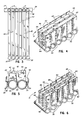
- the evaporator includes an upper header, generally designated 10 and a lower header, generally designated 12.
- the upper header 10 is comprised of a plurality of elongated tubes 14 which are in side by side relation.
- the tubes 14, at the right hand ends 16 as viewed in Fig. 2, are sealed by plugs 18 (Fig. 1).
- the tubes 14 are in fluid communication with the interior of a manifold 20.
- a plug 22 and half of the tubes 14 are in fluid communication with the manifold 20 on one side of the plug 22 while the other half is in fluid communication on the opposite side.
- the manifold 20 can be used either as an inlet or an outlet simply by placing all of the tubes 14 in fluid communication therewith on one side of the plug 22.
- the lower header 12 is made up with an identical number of elongated tubes 30.
- the tubes 30 are in side by side abutting relation as best illustrated in Figs. 3-5 inclusive.
- Their left hand ends 32 (as viewed in Fig. 1) are plugged by means not shown but similar to the plugs 18 or 22 while their right hand ends 34 are in fluid communication with the interior of a manifold 36.
- Fittings 38 similar to conventional reducers may be utilized to establish fluid communication between the tubes 14 and 30 and the respective manifolds 20 and 36.
- the tubes 30, and optionally the tubes 14 as well have a non rectangular cross section which preferably is circular.
- a circular configuration for the headers maximizes the burst pressure that the same can withstand while utilizing a minimum of material for the fabrication of the headers.
- a circular cross section provides maximum strength as well as a relatively lightweight structure.
- the headers 10 and 12 are spaced but parallel and there are provided a plurality of rows of flattened tubes 40.
- the number of rows of tubes 40 is equal to the number of tubes 14 or the number of tubes 30, in the illustrated example, six.
- the flattened tubes 40 are in fluid communication with the interior of corresponding ones of the header tubes 14 and 30 and thus establish fluid communication between the headers 10 and 12.
- incoming refrigerant or the like may enter the manifold 20 through the inlet 24 to enter the associated three tubes 14 and flow downwardly through the tubes 40 to three of the tubes 30.
- the refrigerant will flow from the tubes 30 into the tube 36 where it is conducted to the remaining three of the tubes 30 and upwardly through the tubes 40 to the remaining three tubes 14 and ultimately out the outlet 26.
- the illustrated embodiment is a two-pass evaporator. By eliminating the plug 22 and placing the outlet on the manifold 36, a single-pass evaporator may be formed. Alternatively, additional plugs 22 could be used in varying location to increase the number of passes above if desired.
- the refrigerant inlet will be associated with a manifold such as the manifold 36 associated with the bottom tubes 30 rather than the upper tubes 14.
- the outlet will be associated with the latter.
- manifolds 20 and 36 need not be located on opposite sides of the evaporator as illustrated in Figs. 1 and 2. Generally speaking, they will be on the same side of the evaporator as this will provide a smaller overall envelope for the evaporator.
- the dimension of the tubes 40 transverse to the length of the tubes 30 is slightly less than that dimension of the tubes 30.
- Figs. 3-5 inclusive, there are six substantially identical rows of the tubes 40 and spaces 42 exist between each of the rows of the tubes 40. This is a relatively small spacing and frequently will be on the order of about 6.4 mm (a quarter of an inch) or less.
- the evaporator is built up of a plurality of substantially identical modules, each made up of a header tube 14, a header tube 30, and a plurality of the flattened tubes 40.
- the modules are interconnected by the cross tubes 20 and 36 as well as by serpentine fins 44.
- serpentine fins 44 there are provided a plurality of rows of serpentine fins 44 and, as seen in Fig. 4, each serpentine fin 44 extends through all of the rows 40 and is in heat exchange contact with adjacent tubes or tube pairs in each such row.
- the crests of the serpentine fins preferably are brazed or otherwise bonded to the flat surfaces 46 of the tubes 40.
- the serpentine fins 44 may be provided with louvers shown schematically at 48.
- the assembled components are brazed together with at least the lower header tubes 30 in abutting relation.
- This bond holds the various modules in assembled relationship and for strength, it is desirable that such a bond also exist between the tubes 14.
- the bond 50 serves an additional purpose and thus is made along the entire length of the tubes 30. Specifically, the bond also serves to seal the interface of adjacent tubes 30.
- the air to be conditioned may be flowed through the heat exchanger thus described in the direction of an arrow 51 shown in Fig. 4. That is to say, the same is flowing in the direction of the serpentine fins 44.
- moisture will begin to condense on the serpentine fins 44 as well as the tubes 40.
- Gravity will cause the condensate to flow along the serpentine fins to the tubes 40 while the air flow will tend to cause condensate on the flat walls 46 of the tubes 40 generally to flow to the immediately rearward space 42 between adjacent tubes 40 in adjacent rows. Gravity will then cause the condensate to flow downwardly along the trailing edge of each tube in the space 42 toward the lower header tubes 30. There may be some flow along the forward edges of the tubes 40 as well.
- serpentine fins 44 which extend between the modules as shown in the embodiment of Fig. 4 are dispensed with. Instead, serpentine fins 60 extending between the flat surfaces 46 of adjacent tubes 40 in each row only are utilized. That is to say, the serpentine fins 60 utilized in the embodiment illustrated in Fig. 6 are unique to a given module and do not extend between modules as in the embodiment illustrated in Fig. 4.
- Fig. 7 Still another modified embodiment is illustrated in Fig. 7.
- the individual header tubes 30 and the bonds 50 therebetween are done away with and replaced with a one-piece extrusion, generally designated 62, having the same overall configuration. That is to say, the extrusion 62 defines a plurality of header passages 64 of circular cross section which are parallel to each other and on the same centers as the tubes 30 utilized in the embodiments of Figs. 1-6.
- the extrusion 62 has upper and lower exterior surfaces 66 and 68 of the same general configuration as the assembled header tubes 30 in the embodiment of Figs. 1-6 and therefore includes the upwardly opening concave areas 56 between adjacent passages 64 to serve the same purpose as the concave areas in the embodiment of Figs. 1-6.
- Fig. 8 shows still another embodiment of the invention wherein a single extrusion may be utilized to replace a plurality of tubes, specifically, the flattened tubes 40.
- a single extrusion may be utilized to replace a plurality of tubes, specifically, the flattened tubes 40.
- an elongated, relatively narrow extrusion 68 having the cross section illustrated. It includes opposed, flattened surfaces 70 and 72 that are the counterparts of the surfaces 46 on the flattened tubes 40.
- the extrusion 68 includes a plurality of flow passages 74 which correspond to the interiors of the tubes 40.
- three tube structures each formed of the extrusion 68 illustrated in Fig. 8 could be utilized to replace the eighteen tubes 40 illustrated in, for example, Fig. 6.
- both of the surfaces 70 and 72 are provided with concave areas or longitudinally extending grooves 76 between adjacent passages 74. These concave areas 76 will not be obstructed by serpentine fins and thus provide flow passages as do the spaces 42.
- FIGs. 9 and 10 Still another embodiment of the invention is illustrated in Figs. 9 and 10.
- This embodiment illustrates alternative manifold structures applicable to either the upper header 10 or the lower header 12 or both, which are highly desirable because of the compactness they provide.
- the lower header 12 is made up of a plurality of the tubes 30 although it could just as well be made up of the extrusion 62.
- the ends of the tubes 30 are sealed by means not shown and intermediate the ends thereof, a smaller diameter tube 80 extends generally transversely to the length of the tubes 30 pass through the interiors of all but one of the end tubes 30 although, in some instances, it might even be desirable to extend through all of the tubes 30.
- the tube 80 is sealed to each of the tubes 30 at the various interfaces so as to prevent leakage therebetween and within each of the tubes 30, as shown in Fig. 10, the tube 80 includes one or more apertures 82 in its side wall which thus place the interior 84 of the tube 80 in fluid communication with the interior of the corresponding tube 30.
- the tube 80 may be utilized as an inlet or an outlet. It may also be plugged intermediate its end to provide multiple passes where desirable.
- the outer diameter of the tube 80 will be substantially less than the inner diameter of the tubes 30 to provide spacing between the two as shown in Fig. 10 so as to avoid unduly restricting flow within the tubes 30 as well as to avoid interference between the tube 80 and may tubes 40 or the extrusion 68 shown in Fig. 8 when mounted to the tubes 30.
- the tube 80 may be utilized as a distributor by having any external end, as the end 86 (Fig. 9), plugged.
- an inlet and/or outlet (not shown) is attached to one of the tubes 30 and in fluid communication with the interior thereof. Fluid may enter the tube 80 through the apertures 82 in the tube 30 having the inlet and flow through the interior 84 to exit the apertures 82 into the interior of the other tubes 30.
- an evaporator made according to the invention is ideally suited for mass production because it is made up of substantially identical modules. Furthermore, by use of the unique construction, improved condensate collection results. Bulk and weight are minimized because the header tubes serve a dual purpose in acting as conduits for refrigerant with their inner surfaces acting to confine the refrigerant to the desired flow path and their outer surfaces acting as flow channels for condensate.
Landscapes
- Engineering & Computer Science (AREA)
- Mechanical Engineering (AREA)
- General Engineering & Computer Science (AREA)
- Physics & Mathematics (AREA)
- Thermal Sciences (AREA)
- Chemical & Material Sciences (AREA)
- Combustion & Propulsion (AREA)
- Geometry (AREA)
- Heat-Exchange Devices With Radiators And Conduit Assemblies (AREA)
Claims (12)
Priority Applications (2)
| Application Number | Priority Date | Filing Date | Title |
|---|---|---|---|
| EP91203007A EP0608439B2 (fr) | 1988-01-28 | 1988-11-21 | Echangeur de chaleur avec collection du condensat améliorée |
| AT88310955T ATE76684T1 (de) | 1988-01-28 | 1988-11-21 | Verdampfer mit kondensatsammler. |
Applications Claiming Priority (2)
| Application Number | Priority Date | Filing Date | Title |
|---|---|---|---|
| US149393 | 1988-01-28 | ||
| US07/149,393 US4829780A (en) | 1988-01-28 | 1988-01-28 | Evaporator with improved condensate collection |
Related Child Applications (2)
| Application Number | Title | Priority Date | Filing Date |
|---|---|---|---|
| EP91203007A Division EP0608439B2 (fr) | 1988-01-28 | 1988-11-21 | Echangeur de chaleur avec collection du condensat améliorée |
| EP91203007.9 Division-Into | 1991-11-18 |
Publications (2)
| Publication Number | Publication Date |
|---|---|
| EP0325844A1 EP0325844A1 (fr) | 1989-08-02 |
| EP0325844B1 true EP0325844B1 (fr) | 1992-05-27 |
Family
ID=22530081
Family Applications (2)
| Application Number | Title | Priority Date | Filing Date |
|---|---|---|---|
| EP91203007A Expired - Lifetime EP0608439B2 (fr) | 1988-01-28 | 1988-11-21 | Echangeur de chaleur avec collection du condensat améliorée |
| EP88310955A Expired - Lifetime EP0325844B1 (fr) | 1988-01-28 | 1988-11-21 | Evaporateur avec collection du condensat |
Family Applications Before (1)
| Application Number | Title | Priority Date | Filing Date |
|---|---|---|---|
| EP91203007A Expired - Lifetime EP0608439B2 (fr) | 1988-01-28 | 1988-11-21 | Echangeur de chaleur avec collection du condensat améliorée |
Country Status (12)
| Country | Link |
|---|---|
| US (2) | US4829780A (fr) |
| EP (2) | EP0608439B2 (fr) |
| JP (1) | JP2733593B2 (fr) |
| KR (1) | KR0132297B1 (fr) |
| AR (1) | AR240516A1 (fr) |
| AT (2) | ATE76684T1 (fr) |
| AU (1) | AU596779B2 (fr) |
| BR (1) | BR8900191A (fr) |
| CA (1) | CA1340218C (fr) |
| DE (2) | DE3871515D1 (fr) |
| ES (2) | ES2108029T3 (fr) |
| MX (1) | MX166318B (fr) |
Families Citing this family (46)
| Publication number | Priority date | Publication date | Assignee | Title |
|---|---|---|---|---|
| US5178209A (en) * | 1988-07-12 | 1993-01-12 | Sanden Corporation | Condenser for automotive air conditioning systems |
| JPH02103666U (fr) * | 1989-02-02 | 1990-08-17 | ||
| JPH0616308Y2 (ja) * | 1989-03-08 | 1994-04-27 | サンデン株式会社 | 熱交換器 |
| US4960169A (en) * | 1989-06-20 | 1990-10-02 | Modien Manufacturing Co. | Baffle for tubular heat exchanger header |
| CA2035590A1 (fr) | 1990-02-12 | 1991-08-13 | Gregory G. Hughes | Evaporateur a passes multiples |
| US5152339A (en) * | 1990-04-03 | 1992-10-06 | Thermal Components, Inc. | Manifold assembly for a parallel flow heat exchanger |
| US5107926A (en) * | 1990-04-03 | 1992-04-28 | Thermal Components, Inc. | Manifold assembly for a parallel flow heat exchanger |
| JPH0731030B2 (ja) * | 1991-12-20 | 1995-04-10 | サンデン株式会社 | 熱交換器用ヘッダ−パイプの仕切板組付構造及び組付方法 |
| US5205347A (en) * | 1992-03-31 | 1993-04-27 | Modine Manufacturing Co. | High efficiency evaporator |
| DE4305060C2 (de) * | 1993-02-19 | 2002-01-17 | Behr Gmbh & Co | Gelöteter Wärmetauscher, insbesondere Verdampfer |
| DE9400687U1 (de) * | 1994-01-17 | 1995-05-18 | Thermal-Werke, Wärme-, Kälte-, Klimatechnik GmbH, 68766 Hockenheim | Verdampfer für Klimaanlagen in Kraftfahrzeugen mit Mehrkammerflachrohren |
| US5622219A (en) | 1994-10-24 | 1997-04-22 | Modine Manufacturing Company | High efficiency, small volume evaporator for a refrigerant |
| DE19505403C5 (de) * | 1995-02-17 | 2006-02-23 | Donghwan Ind. Corp., Changwon | Hochleistungsklimaanlage für Busse |
| US5694785A (en) * | 1996-09-18 | 1997-12-09 | Fisher Manufacturing Co., Inc. | Condensate evaporator apparatus |
| DE19719263C2 (de) * | 1997-05-07 | 2002-04-25 | Valeo Klimatech Gmbh & Co Kg | Flachrohrverdampfer mit vertikaler Längserstreckungsrichtung der Flachrohre bei Kraftfahrzeugen |
| AU5121598A (en) * | 1997-05-12 | 1998-12-08 | Norsk Hydro Asa | Heat exchanger |
| US5941303A (en) * | 1997-11-04 | 1999-08-24 | Thermal Components | Extruded manifold with multiple passages and cross-counterflow heat exchanger incorporating same |
| EP0945696A1 (fr) * | 1998-03-27 | 1999-09-29 | Karmazin Products Corporation | Construction de collecteur en aluminium |
| DE19826881B4 (de) * | 1998-06-17 | 2008-01-03 | Behr Gmbh & Co. Kg | Wärmeübertrager, insbesondere Verdampfer |
| FI111029B (fi) * | 1998-09-09 | 2003-05-15 | Outokumpu Oy | Lämmönvaihtoyksikkö ja käyttö |
| US6167716B1 (en) | 1999-07-29 | 2001-01-02 | Fredrick Family Trust | Condensate evaporator apparatus |
| JP2002115934A (ja) * | 2000-10-06 | 2002-04-19 | Denso Corp | 蒸発器および冷凍機 |
| US6640887B2 (en) * | 2000-12-20 | 2003-11-04 | Visteon Global Technologies, Inc. | Two piece heat exchanger manifold |
| DE10139190C1 (de) * | 2001-08-16 | 2002-08-22 | Webasto Thermosysteme Gmbh | Fahrzeugklimasystem mit mehreren Fluidkreisläufen |
| JP3883061B2 (ja) * | 2002-08-12 | 2007-02-21 | 三洋電機株式会社 | スターリング冷熱供給システム |
| EP1447636A1 (fr) | 2003-02-11 | 2004-08-18 | Delphi Technologies, Inc. | Echangeur de chaleur |
| DE10349974A1 (de) * | 2003-10-24 | 2005-05-25 | Behr Gmbh & Co. Kg | Vorrichtung zum Austausch von Wärme |
| DE102004001786A1 (de) * | 2004-01-12 | 2005-08-04 | Behr Gmbh & Co. Kg | Wärmeübertrager, insbesondere für überkritischen Kältekreislauf |
| US20070039723A1 (en) * | 2005-08-18 | 2007-02-22 | Alex Latcau | Header extension to retain core cover and maintain constant compression on outer fins |
| WO2007129851A1 (fr) * | 2006-05-09 | 2007-11-15 | Korea Delphi Automotive Systems Corporation | Échangeur de chaleur pour automobile et procédé de fabrication de celui-ci |
| WO2008045111A1 (fr) * | 2006-10-13 | 2008-04-17 | Carrier Corporation | Échangeur de chaleur multicanaux avec dispositif de détente multi-étage |
| US8307669B2 (en) * | 2007-02-27 | 2012-11-13 | Carrier Corporation | Multi-channel flat tube evaporator with improved condensate drainage |
| US20100031505A1 (en) * | 2008-08-06 | 2010-02-11 | Oddi Frederick V | Cross-counterflow heat exchanger assembly |
| US20100044010A1 (en) * | 2008-08-21 | 2010-02-25 | Corser Don C | Manifold with multiple passages and cross-counterflow heat exchanger incorporating the same |
| US8720224B2 (en) * | 2010-02-12 | 2014-05-13 | REJ Enterprises, LLP | Gravity flooded evaporator and system for use therewith |
| JP5403029B2 (ja) * | 2011-10-07 | 2014-01-29 | ダイキン工業株式会社 | 冷凍装置 |
| JP5604018B2 (ja) | 2012-09-04 | 2014-10-08 | パナソニック株式会社 | 電池ブロックおよびその製造方法 |
| US9777965B2 (en) * | 2013-03-15 | 2017-10-03 | Thar Energy Llc | Countercurrent heat exchanger/reactor |
| US9146045B2 (en) | 2013-08-07 | 2015-09-29 | Climacool Corp | Modular chiller system comprising interconnected flooded heat exchangers |
| JP6300915B2 (ja) * | 2014-06-13 | 2018-03-28 | 三菱電機株式会社 | 熱交換器 |
| DE102015112833A1 (de) | 2015-08-05 | 2017-02-09 | Valeo Klimasysteme Gmbh | Wärmetauscher sowie Fahrzeugklimaanlage |
| WO2017203566A1 (fr) * | 2016-05-23 | 2017-11-30 | 三菱電機株式会社 | Distributeur, collecteur stratifié, échangeur thermique et dispositif de climatisation |
| US11460256B2 (en) | 2016-06-23 | 2022-10-04 | Modine Manufacturing Company | Heat exchanger header |
| US11565955B2 (en) | 2018-09-28 | 2023-01-31 | Neutrasafe Llc | Condensate neutralizer |
| KR102242513B1 (ko) | 2020-09-11 | 2021-04-20 | 주식회사 피쉬 | 결로현상을 이용한 응결수 수집용 증발기 및 이를 이용한 응결수 자원화 시스템 |
| US12123652B2 (en) * | 2020-11-02 | 2024-10-22 | Cooler Master Co., Ltd | Liquid cooling system |
Family Cites Families (50)
| Publication number | Priority date | Publication date | Assignee | Title |
|---|---|---|---|---|
| BE460359A (fr) * | ||||
| FR399933A (fr) * | 1909-02-26 | 1909-07-10 | G Moreux Et Cie Soc | Dispositif de radiateur léger |
| GB362073A (en) * | 1930-10-04 | 1931-12-03 | Serck Radiators Ltd | Improvements relating to heat interchanging apparatus |
| US1899080A (en) * | 1931-10-29 | 1933-02-28 | Res & Dev Corp | Heat exchange device |
| US2093256A (en) * | 1935-01-10 | 1937-09-14 | Still William Joseph | Heat exchange element |
| US2878655A (en) * | 1954-11-26 | 1959-03-24 | Gen Motors Corp | Refrigerating apparatus with condensate director |
| US2874555A (en) * | 1955-12-01 | 1959-02-24 | Gen Motors Corp | Evaporator arrangement |
| US3030782A (en) * | 1959-03-31 | 1962-04-24 | Karmazin John | Capillary tube assembly for evaporators |
| FR1259266A (fr) * | 1960-06-09 | 1961-04-21 | Serck Radiators Ltd | Tubes métalliques à ailettes pour échangeurs de chaleur |
| US3161234A (en) * | 1962-10-16 | 1964-12-15 | United Aircraft Corp | Multipass evaporator |
| GB1027366A (en) † | 1962-11-24 | 1966-04-27 | Svenska Metallverken Ab | An improved radiator and method of making it |
| DE2423440C2 (de) † | 1974-05-14 | 1982-03-04 | Süddeutsche Kühlerfabrik Julius Fr. Behr GmbH & Co KG, 7000 Stuttgart | Brennkraftmaschinen-Mehrkreis-Kühlerblock |
| US3976128A (en) * | 1975-06-12 | 1976-08-24 | Ford Motor Company | Plate and fin heat exchanger |
| US4217953A (en) * | 1976-03-09 | 1980-08-19 | Nihon Radiator Co. Ltd. (Nihon Rajiecta Kabushiki Kaisha) | Parallel flow type evaporator |
| JPS5326694U (fr) * | 1976-08-09 | 1978-03-07 | ||
| FR2414706A1 (fr) * | 1978-01-11 | 1979-08-10 | Chausson Usines Sa | Collecteur a dimensions variables pour echangeur de chaleur et echangeur en faisant application |
| US4434843A (en) * | 1978-04-17 | 1984-03-06 | International Environmental Manufacturing Co. | Heat exchanger apparatus |
| US4470455A (en) * | 1978-06-19 | 1984-09-11 | General Motors Corporation | Plate type heat exchanger tube pass |
| US4274482A (en) * | 1978-08-21 | 1981-06-23 | Nihon Radiator Co., Ltd. | Laminated evaporator |
| JPS55164264A (en) * | 1979-06-08 | 1980-12-20 | Hitachi Ltd | Aqueous coating composition and heat exchanger coated with it |
| JPS5623700A (en) * | 1979-08-03 | 1981-03-06 | Fuji Heavy Ind Ltd | Heat exchanger |
| US4371034A (en) * | 1979-08-03 | 1983-02-01 | Hisaka Works, Limited | Plate type evaporator |
| JPS56153766U (fr) * | 1980-04-18 | 1981-11-17 | ||
| CA1117520A (fr) * | 1980-06-27 | 1982-02-02 | Bozo Dragojevic | Echangeur de chaleur |
| JPS5942615Y2 (ja) * | 1980-10-16 | 1984-12-13 | 株式会社デンソー | 蒸発器 |
| JPS57198993A (en) * | 1981-05-29 | 1982-12-06 | Hitachi Ltd | Crossed fin type heat exchanger |
| DE3133665C2 (de) * | 1981-08-26 | 1984-06-07 | Süddeutsche Kühlerfabrik Julius Fr. Behr GmbH & Co KG, 7000 Stuttgart | Verbindung von Rohren eines Wärmetauscherblocks mit einem Anschlußkasten, insbesondere für einen Verdampfer |
| DE3143332C1 (de) * | 1981-10-31 | 1983-04-14 | Daimler-Benz Ag, 7000 Stuttgart | Waermetauscher mit einem Iuftbeaufschlagbaren Buendel parallel verlaufender Rohre |
| US4487038A (en) * | 1982-04-12 | 1984-12-11 | Diesel Kiki Co., Ltd. | Laminate type evaporator |
| JPS58217196A (ja) * | 1982-06-10 | 1983-12-17 | Mitsubishi Electric Corp | 熱交換器 |
| US4614231A (en) * | 1982-08-09 | 1986-09-30 | Murray Corporation | Evaporators |
| US4513577A (en) * | 1982-11-19 | 1985-04-30 | Wilson Neill R | Evaporator and method of operation |
| JPS5993181A (ja) * | 1982-11-19 | 1984-05-29 | Hitachi Ltd | 液膜蒸発式熱交換器 |
| JPS5995359A (ja) * | 1982-11-25 | 1984-06-01 | カルソニックカンセイ株式会社 | 蒸発器 |
| JPS59129392A (ja) * | 1983-01-10 | 1984-07-25 | Nippon Denso Co Ltd | 熱交換器 |
| US4566290A (en) * | 1983-03-28 | 1986-01-28 | Arvin Industries, Inc. | Capillary fin media |
| JPS6012088U (ja) * | 1983-06-30 | 1985-01-26 | カルソニックカンセイ株式会社 | 熱交換器 |
| JPS6030971U (ja) * | 1983-08-08 | 1985-03-02 | カルソニックカンセイ株式会社 | 異形管エバポレ−タ |
| US4621685A (en) * | 1983-09-12 | 1986-11-11 | Diesel Kiki Co., Ltd. | Heat exchanger comprising condensed moisture drainage means |
| JPS60101156A (ja) * | 1983-11-07 | 1985-06-05 | Sanyo Chem Ind Ltd | アルミニウム製熱交換器またはそのフイン材用親水性皮膜形成剤 |
| DE8409717U1 (de) * | 1984-03-27 | 1987-01-08 | Schick, Josef Hubert, 5203 Much | Vorrichtung zum Wärme- und Stoffaustausch zwischen zwei oder mehr strömungsfähigen Medien |
| JPS60176375U (ja) * | 1984-05-01 | 1985-11-22 | サンデン株式会社 | 熱交換器 |
| US4621687A (en) * | 1984-10-11 | 1986-11-11 | Nihon Radiator Co., Ltd. | Flat tube heat exchanger having corrugated fins with louvers |
| US4600053A (en) * | 1984-11-23 | 1986-07-15 | Ford Motor Company | Heat exchanger structure |
| FR2574175B1 (fr) * | 1984-12-04 | 1989-02-10 | Sanden Corp | Echangeur de chaleur en aluminium |
| US4592414A (en) * | 1985-03-06 | 1986-06-03 | Mccord Heat Transfer Corporation | Heat exchanger core construction utilizing a plate member adaptable for producing either a single or double pass flow arrangement |
| CA1202957A (fr) * | 1985-03-29 | 1986-04-08 | Guy St-Pierre | Serpentin de refroidissement a circulation en chute |
| US4693307A (en) * | 1985-09-16 | 1987-09-15 | General Motors Corporation | Tube and fin heat exchanger with hybrid heat transfer fin arrangement |
| JPS62202994A (ja) * | 1986-02-28 | 1987-09-07 | Hisaka Works Ltd | 液流下型プレート式蒸発器における給液分散装置 |
| JPH0682037B2 (ja) * | 1986-06-23 | 1994-10-19 | 昭和アルミニウム株式会社 | 熱交換器 |
-
1988
- 1988-01-28 US US07/149,393 patent/US4829780A/en not_active Ceased
- 1988-11-15 CA CA000583187A patent/CA1340218C/fr not_active Expired - Fee Related
- 1988-11-17 AU AU25668/88A patent/AU596779B2/en not_active Ceased
- 1988-11-21 DE DE8888310955T patent/DE3871515D1/de not_active Expired - Fee Related
- 1988-11-21 EP EP91203007A patent/EP0608439B2/fr not_active Expired - Lifetime
- 1988-11-21 ES ES91203007T patent/ES2108029T3/es not_active Expired - Lifetime
- 1988-11-21 EP EP88310955A patent/EP0325844B1/fr not_active Expired - Lifetime
- 1988-11-21 AT AT88310955T patent/ATE76684T1/de not_active IP Right Cessation
- 1988-11-21 AT AT91203007T patent/ATE158648T1/de not_active IP Right Cessation
- 1988-11-21 ES ES198888310955T patent/ES2032978T3/es not_active Expired - Lifetime
- 1988-11-21 DE DE3856032T patent/DE3856032T3/de not_active Expired - Fee Related
- 1988-12-30 MX MX014401A patent/MX166318B/es unknown
-
1989
- 1989-01-05 KR KR1019890000036A patent/KR0132297B1/ko not_active Expired - Fee Related
- 1989-01-17 BR BR898900191A patent/BR8900191A/pt not_active IP Right Cessation
- 1989-01-23 JP JP1012064A patent/JP2733593B2/ja not_active Expired - Lifetime
- 1989-01-26 AR AR31308289A patent/AR240516A1/es active
-
1991
- 1991-04-02 US US07/679,660 patent/USRE37040E1/en not_active Expired - Lifetime
Also Published As
| Publication number | Publication date |
|---|---|
| US4829780A (en) | 1989-05-16 |
| BR8900191A (pt) | 1989-09-12 |
| DE3871515D1 (de) | 1992-07-02 |
| JPH0217387A (ja) | 1990-01-22 |
| USRE37040E1 (en) | 2001-02-06 |
| AR240516A1 (es) | 1990-04-30 |
| ATE76684T1 (de) | 1992-06-15 |
| KR890012144A (ko) | 1989-08-24 |
| CA1340218C (fr) | 1998-12-15 |
| ES2108029T3 (es) | 1997-12-16 |
| ES2032978T3 (es) | 1993-03-01 |
| EP0325844A1 (fr) | 1989-08-02 |
| ATE158648T1 (de) | 1997-10-15 |
| EP0608439B1 (fr) | 1997-09-24 |
| AU596779B2 (en) | 1990-05-10 |
| EP0608439A1 (fr) | 1994-08-03 |
| JP2733593B2 (ja) | 1998-03-30 |
| DE3856032D1 (de) | 1997-10-30 |
| MX166318B (es) | 1992-12-29 |
| AU2566888A (en) | 1989-08-03 |
| EP0608439B2 (fr) | 2002-09-25 |
| DE3856032T2 (de) | 1998-03-26 |
| DE3856032T3 (de) | 2003-05-22 |
| KR0132297B1 (ko) | 1998-04-20 |
Similar Documents
| Publication | Publication Date | Title |
|---|---|---|
| US4829780A (en) | Evaporator with improved condensate collection | |
| US5341870A (en) | Evaporator or evaporator/condenser | |
| US5372188A (en) | Heat exchanger for a refrigerant system | |
| EP0563471B1 (fr) | Evaporateur | |
| US5086835A (en) | Heat exchanger | |
| US5279360A (en) | Evaporator or evaporator/condenser | |
| US5314013A (en) | Heat exchanger | |
| EP2402695B1 (fr) | Évaporateur utilisant des tubes à microcanaux | |
| US5592830A (en) | Refrigerant condenser with integral receiver | |
| EP0501736B1 (fr) | Evaporateur | |
| US6016864A (en) | Heat exchanger with relatively flat fluid conduits | |
| EP0622599B1 (fr) | Echangeur de chaleur | |
| US5099913A (en) | Tubular plate pass for heat exchanger with high volume gas expansion side | |
| US20060054310A1 (en) | Evaporator using micro-channel tubes | |
| US7303003B2 (en) | Heat exchanger | |
| US5176200A (en) | Method of generating heat exchange | |
| US20020050337A1 (en) | Condenser and tube therefor | |
| US4892143A (en) | Heat exchanger | |
| JP2007518051A (ja) | 特に超臨界冷凍サイクル用の熱交換器 | |
| JP6785137B2 (ja) | エバポレータ | |
| US20070056718A1 (en) | Heat exchanger and duplex type heat exchanger | |
| US7918266B2 (en) | Heat exchanger | |
| JPH0452498A (ja) | 複式熱交換器 | |
| EP0442646A2 (fr) | Evaporateur à passes multiples | |
| JPH05215482A (ja) | 熱交換器 |
Legal Events
| Date | Code | Title | Description |
|---|---|---|---|
| PUAI | Public reference made under article 153(3) epc to a published international application that has entered the european phase |
Free format text: ORIGINAL CODE: 0009012 |
|
| AK | Designated contracting states |
Kind code of ref document: A1 Designated state(s): AT DE ES FR GB IT NL SE |
|
| 17P | Request for examination filed |
Effective date: 19890829 |
|
| 17Q | First examination report despatched |
Effective date: 19900507 |
|
| GRAA | (expected) grant |
Free format text: ORIGINAL CODE: 0009210 |
|
| AK | Designated contracting states |
Kind code of ref document: B1 Designated state(s): AT DE ES FR GB IT NL SE |
|
| REF | Corresponds to: |
Ref document number: 76684 Country of ref document: AT Date of ref document: 19920615 Kind code of ref document: T |
|
| ITF | It: translation for a ep patent filed | ||
| REF | Corresponds to: |
Ref document number: 3871515 Country of ref document: DE Date of ref document: 19920702 |
|
| ET | Fr: translation filed | ||
| REG | Reference to a national code |
Ref country code: ES Ref legal event code: FG2A Ref document number: 2032978 Country of ref document: ES Kind code of ref document: T3 |
|
| PLBE | No opposition filed within time limit |
Free format text: ORIGINAL CODE: 0009261 |
|
| STAA | Information on the status of an ep patent application or granted ep patent |
Free format text: STATUS: NO OPPOSITION FILED WITHIN TIME LIMIT |
|
| 26N | No opposition filed | ||
| EAL | Se: european patent in force in sweden |
Ref document number: 88310955.5 |
|
| PGFP | Annual fee paid to national office [announced via postgrant information from national office to epo] |
Ref country code: FR Payment date: 20011031 Year of fee payment: 14 |
|
| PGFP | Annual fee paid to national office [announced via postgrant information from national office to epo] |
Ref country code: SE Payment date: 20011101 Year of fee payment: 14 Ref country code: DE Payment date: 20011101 Year of fee payment: 14 |
|
| PGFP | Annual fee paid to national office [announced via postgrant information from national office to epo] |
Ref country code: NL Payment date: 20011102 Year of fee payment: 14 |
|
| PGFP | Annual fee paid to national office [announced via postgrant information from national office to epo] |
Ref country code: AT Payment date: 20011105 Year of fee payment: 14 |
|
| PGFP | Annual fee paid to national office [announced via postgrant information from national office to epo] |
Ref country code: GB Payment date: 20011107 Year of fee payment: 14 |
|
| PGFP | Annual fee paid to national office [announced via postgrant information from national office to epo] |
Ref country code: ES Payment date: 20011207 Year of fee payment: 14 |
|
| REG | Reference to a national code |
Ref country code: GB Ref legal event code: IF02 |
|
| PG25 | Lapsed in a contracting state [announced via postgrant information from national office to epo] |
Ref country code: GB Free format text: LAPSE BECAUSE OF NON-PAYMENT OF DUE FEES Effective date: 20021121 Ref country code: AT Free format text: LAPSE BECAUSE OF NON-PAYMENT OF DUE FEES Effective date: 20021121 |
|
| PG25 | Lapsed in a contracting state [announced via postgrant information from national office to epo] |
Ref country code: SE Free format text: LAPSE BECAUSE OF NON-PAYMENT OF DUE FEES Effective date: 20021122 Ref country code: ES Free format text: LAPSE BECAUSE OF NON-PAYMENT OF DUE FEES Effective date: 20021122 |
|
| PG25 | Lapsed in a contracting state [announced via postgrant information from national office to epo] |
Ref country code: NL Free format text: LAPSE BECAUSE OF NON-PAYMENT OF DUE FEES Effective date: 20030601 |
|
| PG25 | Lapsed in a contracting state [announced via postgrant information from national office to epo] |
Ref country code: DE Free format text: LAPSE BECAUSE OF NON-PAYMENT OF DUE FEES Effective date: 20030603 |
|
| EUG | Se: european patent has lapsed | ||
| GBPC | Gb: european patent ceased through non-payment of renewal fee | ||
| PG25 | Lapsed in a contracting state [announced via postgrant information from national office to epo] |
Ref country code: FR Free format text: LAPSE BECAUSE OF NON-PAYMENT OF DUE FEES Effective date: 20030731 |
|
| NLV4 | Nl: lapsed or anulled due to non-payment of the annual fee |
Effective date: 20030601 |
|
| REG | Reference to a national code |
Ref country code: FR Ref legal event code: ST |
|
| REG | Reference to a national code |
Ref country code: ES Ref legal event code: FD2A Effective date: 20031213 |
|
| PG25 | Lapsed in a contracting state [announced via postgrant information from national office to epo] |
Ref country code: IT Free format text: LAPSE BECAUSE OF NON-PAYMENT OF DUE FEES;WARNING: LAPSES OF ITALIAN PATENTS WITH EFFECTIVE DATE BEFORE 2007 MAY HAVE OCCURRED AT ANY TIME BEFORE 2007. THE CORRECT EFFECTIVE DATE MAY BE DIFFERENT FROM THE ONE RECORDED. Effective date: 20051121 |