EP0326070A2 - Hydraulic actuator for performing impact tension and piercing tests - Google Patents
Hydraulic actuator for performing impact tension and piercing tests Download PDFInfo
- Publication number
- EP0326070A2 EP0326070A2 EP89101171A EP89101171A EP0326070A2 EP 0326070 A2 EP0326070 A2 EP 0326070A2 EP 89101171 A EP89101171 A EP 89101171A EP 89101171 A EP89101171 A EP 89101171A EP 0326070 A2 EP0326070 A2 EP 0326070A2
- Authority
- EP
- European Patent Office
- Prior art keywords
- piston
- sample
- feed
- working piston
- piston rod
- Prior art date
- Legal status (The legal status is an assumption and is not a legal conclusion. Google has not performed a legal analysis and makes no representation as to the accuracy of the status listed.)
- Withdrawn
Links
Images

Classifications
-
- G—PHYSICS
- G01—MEASURING; TESTING
- G01N—INVESTIGATING OR ANALYSING MATERIALS BY DETERMINING THEIR CHEMICAL OR PHYSICAL PROPERTIES
- G01N3/00—Investigating strength properties of solid materials by application of mechanical stress
- G01N3/30—Investigating strength properties of solid materials by application of mechanical stress by applying a single impulsive force, e.g. by falling weight
- G01N3/307—Investigating strength properties of solid materials by application of mechanical stress by applying a single impulsive force, e.g. by falling weight generated by a compressed or tensile-stressed spring; generated by pneumatic or hydraulic means
Definitions
- plastics especially painted plastics
- body parts in motor vehicles require testing them for impact strength at temperatures between + 23 ° C and - 30 ° C.
- the test is usually carried out as a tensile impact test according to DIN 53 448 with pendulum impact testers or with hydraulic universal testing machines , and as a puncture test with falling bolt factories or the already mentioned hydraulic universal testing machines according to DIN 53 443.
- instrumented test methods According to the current state of knowledge, qualified statements about the suitability of plastics as body parts can only be obtained with so-called instrumented test methods.
- Hydraulic universal testing machines the working axes of which are usually arranged vertically, carry out impact tensile tests in which the upper end of the specimen is connected to a force transducer mounted on the upper crossbeam of the machine.
- the lower end of the sample is connected via a further clamping head to a driver which loosely dips into a sleeve which is attached to the upper piston rod of the hydraulic cylinder.
- the construction of these hydraulic cylinders corresponds to conventional hydraulic cylinders with a piston rod on both sides.
- the sleeve forms a lead section, which the relatively heavy piston of the cylinder needs to accelerate to the specified speed. Then the upper end of the sleeve takes the carrier with it and stretches and tears the sample.
- the force transducer measures the force curve, while a displacement transducer attached to the lower piston rod measures the path.
- a clamping device is mounted on the upper end of the piston rod, in which the disk-shaped sample is clamped.
- the puncture body is attached to the upper crossbar, According to DIN 53 443, a bolt with a diameter of 20 mm, the end of which faces the sample forms a hemisphere.
- the force sensor should be located in the puncture body as close as possible to the hemispherical end. The specimen and the puncture body must be so far apart that the piston can accelerate to the specified nominal speed with the clamping device.
- Constructions are also known in which the piercing body is fastened to the piston of the hydraulic cylinder and the tensioning device is fixed.
- Disadvantages of the impact and puncture tests described on hydraulic universal testing machines are the impact of the driver on the upper end of the sleeve in the impact tensile test and the impact of the sample on the puncture body in the case of the puncture test. Bounce vibrations are triggered, which overlap the force signal and make evaluation difficult or completely impossible.
- the impact tensile testing machine according to DE Patent 352947o avoids this problem, because there a very light working piston is directly connected to the sample, which generates bounce-free signals.
- the impact tensile testing machine according to DE Patent 352947O is of limited use bar as it can only be used for impact tensile tests.
- the object of the invention is to find a testing machine system that is suitable with little changes both for the impact test and for the puncture test, is much cheaper to buy than the machines described, the operating level of which is at the level of test mechanics or laboratory assistants, and that delivers comparable and reproducible, undistorted signals to various test centers. This task is solved with the characterizing features of the claims.
- hydraulic universal testing machines are equipped with a cylinder that has a piston with a piston rod on both sides.
- This piston is relatively heavy and therefore requires a relatively large distance to accelerate to its nominal speed.
- this heavy piston and thus the acceleration path and the coupling process for introducing force into the sample are avoided.
- a very light working piston already comes into contact with the sample before the force is actually applied. It can be accelerated in a fraction of a millisecond, so an acceleration distance for the working piston is unnecessary.
- This acceleration path is arranged between the working piston and an additional feed piston.
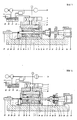
- a feed piston (3) is arranged in a one-piece housing (1) concentrically with a working piston (2), Figure 1.
- the area of the feed piston (3) is several times the area of the working piston (2).
- the working piston (2) which is much smaller than the housing bore, which corresponds to the diameter of the feed piston (3), is with its front Piston rod (8) in the front housing cover (12), and with its rear piston rod (14) in the rear housing cover (13).
- a clamping head (10) is clamped to the sample (11) on both sides.
- the clamping heads (10) are connected on one side to the front piston rod (8) and on the other side to the force sensor (25) via plug connections (9).
- the force sensor is attached to the frame (24).
- the servo valve (5) is attached to the housing (1). It is connected by line (28) to the front space (34) of the housing bore and by line (29) to the rear space (35) of the housing bore.
- An adjustable throttle (4) is arranged in the line (29) through which the oil displaced by the feed piston (3) flows out during the test process.
- the servo valve (5) opens the connection P to B and A to T.
- the oil flowing from the accumulator (30) in the space (34) moves the feed piston (3) towards the working piston (2) and accelerates until it reaches a speed specified by the setting of the throttle (4).
- the feed piston (3) has on its side facing the working piston (2) a pressure chamber (7) into which the working piston (2) is fitted with minimal play.
- the working piston (2) blocks the pressure chamber (7) in which an oil cushion is formed.
- the working piston (2) now floats on this oil cushion and is carried by the feed piston (3).
- the sample (11) is stretched and torn. While the feed piston (3) runs through the acceleration section (6), the displaced oil must flow around the working piston (2).
- the pressure acting on the working piston in the pressure chamber corresponds to the usual pressures in servo-hydraulic testing machines.
- the force to be applied to accelerate the working piston (2) and to withdraw the sample (11) from the feed piston (3) brakes the feed piston. This reduces the pressure drop between the accumulator (30) and the space (34), ie the pressure on this side of the feed piston (3) increases.
- the pressure drop between space (35) and throttle (4) to tank (31) is reduced, ie the pressure on the side of the feed piston facing the working piston (2) drops.
- the pressure required to overcome the flow resistances is proportional to the flow velocity in a square.
- a slight reduction in the speed of the feed piston (3) and thus the flow rate in the system is therefore sufficient to generate a pressure difference on the feed piston which is sufficient to accelerate the working piston and to stretch the sample until it breaks.
- the reduction in the speed of the feed piston is less than the permissible tolerance of the test speed.
- the system is self-regulating due to this design, the large area of the feed piston (3) and the throttle (4) in the drain, which has the most significant part in the pressure difference building up and down on the feed piston.
- the front piston rod (8) is provided at its end with a steep taper (15), which is used to hold the clamping bell (17) with the sample (18), and a disc (16) is mounted on the rear piston rod (14) , Figure 2.
- the working piston (2) is now arranged between the front housing cover (12) and the feed piston (3), and the throttle (4) lies in the line (28).
- a counter cylinder (19) is arranged on the frame (24) such that its axis is aligned with the axis of the working piston (2).
- the piercing body (21) is attached to its piston rod (20).
- the force sensor (25) is arranged behind the hemispherical tip of the piercing body, in accordance with the requirements of DIN 53 443.
- the wiper (22) is located between the counter-cylinder (19) and the housing (1).
- P is connected to B and A to T in the servo valve (5), the feed piston (3) presses the disc (16) against the rear housing cover (13), and the end of the rear piston rod (14) against the spring (23). Since the axis of the puncture testing machine is arranged vertically, the clamping bell (17) can simply be placed on the non-self-holding steep taper (15) of the front piston rod (8) without any further fastening elements. she can This means that it can be easily inserted and removed from the testing machine with one hand and without tools. This is important for temperature-controlled samples.
- a plurality of clamping bells are expediently used, into which the disk-shaped puncture samples (18) are clamped outside the testing machine. These tension bells are brought to the required temperature in a separate temperature control chamber. When the bell and sample have reached the temperature, the bell with the sample is removed from the temperature control chamber and placed on the steep taper (15) of the piston rod (8) and the sample is pierced. A maximum of 5 seconds elapse between removal from the temperature control chamber and puncturing. This ensures that the sample, which is largely shielded from room temperature by the clamping bell, remains at its temperature until it is pierced.
- a puncture test has the following sequence: A clamping bell (17) with sample (18) is placed on the steep taper (15) of the piston rod (8), and the control is started via a two-hand safety device.
- the piston rod (20) of the counter cylinder (19) moves forward until the tip of the piercing body (21) is approx. 1-2 mm in front of the surface of the sample (18), Figure 3.
- P in the servo valve (5) with A and B connected to T As a result, the feed piston (3) is moved in the direction of the working piston (2) and the disc (16) is released.
- the very light working piston (2) with piston rods (8 + 14) and the likewise very light clamping bell (17) with sample (18) are opened in a fraction of a millisecond accelerates the same speed as the feed piston (3), thereby piercing the sample.
- the clamping bell with the sample is pushed over the piercing body until the clamping bell hits the stripper (22), which is made of an elastic material, Figure 4.
- the distance that the clamping bell travels is measured with the displacement transducer (27) .
- the counter-cylinder (19) then pulls the puncture body (21) back, and a tough sample that may adhere to the puncture body is stripped off.
- the servo valve (5) reverses and the feed piston (3) pushes the working piston with piston rods and clamping bell back into the starting positions via the disc (16), Figure 2.
Landscapes
- Physics & Mathematics (AREA)
- Health & Medical Sciences (AREA)
- Life Sciences & Earth Sciences (AREA)
- Chemical & Material Sciences (AREA)
- Analytical Chemistry (AREA)
- Biochemistry (AREA)
- General Health & Medical Sciences (AREA)
- General Physics & Mathematics (AREA)
- Immunology (AREA)
- Pathology (AREA)
- Investigating Strength Of Materials By Application Of Mechanical Stress (AREA)
Abstract
Werden lackierte und unlackierte Kunststoffe im Kfz-Karosseriebereich eingesetzt, müssen sie auf Schlagzähigkeit im Temperaturbereich + 23° C bis - 30° C geprüft werden. Dies erfolgt als instrumentierte Schlagzugprüfung in Anlehnung an DIN 53 448, oder als instrumentierter Durchstoßversuch nach DIN 53 443. Lackhersteller und Kunststoffverarbeiter als Zulieferer der Kfz-Industrie sind vielfach mittelständische Betriebe. Hydraulische Universalprüfmaschinen, mit denen die beschriebenen Versuche begrenzt durchgeführt werden können, liegen sowohl in der Anschaffung als auch im Betrieb außerhalb des Kostenrahmens dieser Betriebe.
Ein Prüfmaschinensystem mit einem hydraulischen Antrieb mit den kennzeichnenden Merkmalen der Patentansprüche kann das Problem lösen.
In einem Gehäuse (1) ist konzentrisch zu einem Arbeitskolben (2) ein Vorschubkolben (3) angeordnet. Öffnet das Servoventil (5), wird der Vorschubkolben (3) in Richtung Arbeitskolben (2) mit einer durch die Drossel (4) vorgegebenen Geschwindigkeit verschoben, und nimmt den Arbeitskolben (2) mit, wodurch die Schlagzugprobe (11) gedehnt und zerrissen wird. Die Druckkammer (7) dämpft den Aufschlag und verhindert Prellschwingungen, die das Kraftsignal stören würden.
Beim Durchstoßversuch ist der Funktionsablauf gleich, nur wird hier die Kolbenstange (8) aus dem Gehäuse (1) gestoßen. 
A testing machine system with a hydraulic drive with the characterizing features of the claims can solve the problem.
A feed piston (3) is arranged in a housing (1) concentrically with a working piston (2). When the servo valve (5) opens, the feed piston (3) is moved in the direction of the working piston (2) at a speed specified by the throttle (4), and takes the working piston (2) with it, causing the impact tensile test (11) to stretch and tear . The pressure chamber (7) dampens the impact and prevents bouncing vibrations that would disrupt the force signal.
The functional sequence of the puncture test is the same, only the piston rod (8) is pushed out of the housing (1).
Description
Der Einsatz von Kunststoffen, vor allem lackierten Kunststoffen als Karosserieteile in Kraftfahrzeugen erfordert eine Prüfung derselben auf Schlagzähigkeit bei Temperaturen zwischen + 23° C und - 30° C. Die Prüfung erfolgt in der Regel als Schlagzugversuch nach DIN 53 448 mit Pendelschlagwerken oder mit hydraulischen Universalprüfmaschinen, und als Durchstoßversuch mit Fallbolzenwerken oder den bereits erwähnten hydraulischen Universalprüfmaschinen nach DIN 53 443. Eine qualifizierte Aussage über die Eignung von Kunststoffen als Karosserieteile kann nach heutigem Wissensstand nur mit sogennanten instrumentierten Prüfverfahren gewonnen werden. Bei diesen instrumentierten Prüfverfahren, angewendet im Schlagzugversuch in Anlehnung an DIN 53 448, und im Durchstoßversuch nach DIN 53 443, wird die während der Dehnung der Probe entstehende Kraft über dem Verformungsweg mittels elektronischen Kraftaufnehmern gemessen, und als Kraft-Weg-Diagramm ausgegeben. Aus diesem Diagramm kann die Arbeitsaufnahme der Probe, und damit die Schlagzähigkeit ermittelt werden. Voraussetzung ist, daß der Kraftverlauf des Diagramms der an der Probe wirkenden Kraft entspricht, und nicht durch Prell- oder sonstige Schwingungen überlagert ist, welche eine Auswertung erschweren oder unmöglich machen. Als Prüfmaschinen kommen in der Praxis nur noch die hydraulischen Universalprüfmaschinen zum Einsatz, denn nur mit ihnen können Prüfungen über einen ralativ großen Geschwindigkeitsbereich mit konstanter Prüfgeschwindigkeit gemacht werden. Sie haben jedoch auch Nachteile, wie später dargelegt wird.The use of plastics, especially painted plastics, as body parts in motor vehicles requires testing them for impact strength at temperatures between + 23 ° C and - 30 ° C. The test is usually carried out as a tensile impact test according to DIN 53 448 with pendulum impact testers or with hydraulic universal testing machines , and as a puncture test with falling bolt factories or the already mentioned hydraulic universal testing machines according to DIN 53 443. According to the current state of knowledge, qualified statements about the suitability of plastics as body parts can only be obtained with so-called instrumented test methods. In these instrumented test methods, used in the impact tensile test based on DIN 53 448 and in the puncture test according to DIN 53 443, the force generated during the stretching of the sample is measured via the deformation path using electronic force transducers and output as a force-displacement diagram. From this diagram, the work start of the sample and thus the impact strength can be determined. The prerequisite is that the force curve of the diagram corresponds to the force acting on the sample and is not superimposed by bouncing or other vibrations which make evaluation difficult or impossible. In practice, only the hydraulic universal testing machines are used as testing machines, because only with them can tests be carried out over a relatively large speed range with a constant testing speed. However, they also have disadvantages, as will be explained later.
Alle Prüfmaschinen, bei denen eine Masse beschleunigt wird, wie z.B. Pendelschlagwerke und Fallbolzenwerke, können nur in einem engen Geschwindigkeitsbereich eingesetzt werden. Geschwindigkeiten über 5,5 m/s sind aus technischen Gründen kaum realisierbar, bei Geschwindigkeiten unter 2,5 m/s wird die gespeicherte kinetische Energie so klein, daß sie zur Zerstörung der Probe nicht mehr ausreicht, oder zumindest die Geschwindigkeit über dem Verformungsweg stark abfällt, was das Resultat verfälscht. Daher soll auf diese Prüfmaschinen im weiteren nicht mehr eingegangen werden. In dem DE Patent 352947o ist eine neue Schlagzugprüfmaschine beschrieben, die zur Durchführung von Schlagzugversuchen gut geeignet ist. Durchstoßversuche können mit dieser Maschine nicht gemacht werden. In EP 0079979 B1 ist eine hydraulische Belastungseinheit, insbesondere für Katapultanlagen, beschrieben.All testing machines where a mass is accelerated, e.g. Pendulum impact testers and fall bolt mechanisms can only be used in a narrow speed range. Speeds above 5.5 m / s are hardly feasible for technical reasons; at speeds below 2.5 m / s, the stored kinetic energy becomes so small that it is no longer sufficient to destroy the sample, or at least the speed over the deformation path is strong drops, which falsifies the result. Therefore, these testing machines will no longer be discussed in the following. DE 352947o describes a new impact tensile testing machine which is well suited for carrying out impact tensile tests. Puncture attempts cannot be made with this machine. EP 0079979 B1 describes a hydraulic loading unit, in particular for catapult systems.
Mit hydraulischen Universalprüfmaschinen, deren Arbeitsachse in der Regel vertikal angeordnet ist, werden Schlagzugversuche durchgeführt in dem die Probe mit dem oberen Ende über einen Spannkopf mit einem Kraftaufnehmer verbunden ist, der an der oberen Traverse der Maschine montiert ist. Das untere Ende der Probe ist über einen weiteren Spannkopf mit einem Mitnehmer verbunden, der lose in eine Hülse taucht, die an der oberen Kolbenstange des Hydraulikzylinders befestigt ist. Diese Hydraulikzylinder entsprechen in ihrem Aufbau konventionellen Hydraulikzylindern mit beidseitiger Kolbenstange. Die Hülse bildet eine Vorlaufstrecke, die der relativ schwere Kolben des Zylinders benötigt, um auf die vorgegebene Geschwindigkeit zu beschleunigen. Danach nimmt das obere Ende der Hülse den Mitnehmer mit und dehnt und zerreißt dadurch die Probe. Der Kraftaufnehmer mißt den Kraftverlauf, während ein an der unteren Kolbenstange befestigter Wegaufnehmer den Weg mißt.
Beim Durchstoßversuch mit hydraulischen Universalprüfmaschinen wird auf das obere Ende der Kolbenstange eine Spannvorrichtung montiert, in der die scheibenförmige Probe gespannt wird. An der oberen Quertraverse wird der Durchstoßkörper befestigt, nach DIN 53 443 ein Bolzen mit 20 mm Durchmesser, dessen der Probe zugewandtes Ende eine Halbkugel bildet. Der Kraftsenor soll laut Norm im Durchstoßkörper möglichst nahe dem halbkugligen Ende angeordnet werden. Probe und Durchstoßkörper müssen so weit von einander entfernt sein, daß der Kolben mit der Spannvorrichtung auf die vorgegebene Nenngeschwindigkeit beschleunigen kann. Es sind auch Konstruktionen bekannt, bei denen der Durchstoßkörper am Kolben des Hydraulikzylinders befestigt ist und die Spannvorrichtung fest steht.
Nachteilig bei den beschriebenen Schlagzug- und Durchstoßprüfungen auf hydraulischen Universalprüfmaschinen ist beim Schlagzugversuch das Auftreffen des Mitnehmers auf das obere Ende der Hülse, und beim Durchstoßversuch das Auftreffen der Probe auf den Durchstoßkörper. Dabei werden Prellschwingungen ausgelöst, die das Kraftsignal überlagern und eine Auswertung erschweren oder ganz unmöglich machen.
Die Schlagzugprüfmaschine nach DE Patent 352947o vermeidet dieses Problem, denn dort ist ein sehr leichter Arbeitskolben direkt mit der Probe verbunden, wodurch prellfreie Signale erzeugt werden.
Kraftfahrzeughersteller, Kunststoffhersteller, Lackhersteller und Kunststoffverarbeiter benötigen ein Prüfmaschinensystem, das es gestattet, unlackierte und lackierte Kunststoffe vergleichbar und reproduzierbar auf Schlagzähigkeit bei Temperaturen zwischen + 23° C und - 30° C zu prüfen. Da in den beiden letztgenannten Unternehmensgruppen vielfach mittelständische Betriebe vertreten sind, für die aufwendige Prüfverfahren, deren Kosten in keinem Verhältnis zum Ertrag stehen, nicht in Frage kommen, diese Prüfungen jedoch erforderlich sind, ist es volkswirtschaftlich wichtig, ein in Anschaffung und Betrieb kostengünstiges Prüfmaschinensystem zu finden.
Die beschriebenen hydraulischen Universalprüfmaschinen liegen sowohl in der Anschaffung als auch durch die durch anspruchsvolle Bedienung verursachten Personalkosten weit außerhalb des Kostenrahmens solcher mittelständischen Betriebe. Hinzu kommt die unbefriedigende Qualität der Kraftsignale. Die Schlagzugprüfmaschine nach DE Patent 352947O ist nur begrenzt brauch bar, da sie nur für Schlagzugversuche verwendet werden kann.
Aufgabe der Erfindung ist es, ein Prüfmaschinensystem zu finden, das mit geringen Änderungen sowohl für den Schlagzugversuch als auch für den Durchstoßversuch geeignet ist, in der Anschaffung wesentlich billiger ist als die beschriebenen Maschinen, dessen Bedienniveau auf der Ebene von Prüfmechanikern oder Laborantinnen liegt, und das verschiedenen Prüfstellen vergleich- und reproduzierbare unverprellte Signale liefert.
Diese Aufgabenstellung wird mit den kennzeichnenden Merkmalen der Patentansprüche gelöst.Hydraulic universal testing machines, the working axes of which are usually arranged vertically, carry out impact tensile tests in which the upper end of the specimen is connected to a force transducer mounted on the upper crossbeam of the machine. The lower end of the sample is connected via a further clamping head to a driver which loosely dips into a sleeve which is attached to the upper piston rod of the hydraulic cylinder. The construction of these hydraulic cylinders corresponds to conventional hydraulic cylinders with a piston rod on both sides. The sleeve forms a lead section, which the relatively heavy piston of the cylinder needs to accelerate to the specified speed. Then the upper end of the sleeve takes the carrier with it and stretches and tears the sample. The force transducer measures the force curve, while a displacement transducer attached to the lower piston rod measures the path.
In the puncture test with hydraulic universal testing machines, a clamping device is mounted on the upper end of the piston rod, in which the disk-shaped sample is clamped. The puncture body is attached to the upper crossbar, According to DIN 53 443, a bolt with a diameter of 20 mm, the end of which faces the sample forms a hemisphere. According to the standard, the force sensor should be located in the puncture body as close as possible to the hemispherical end. The specimen and the puncture body must be so far apart that the piston can accelerate to the specified nominal speed with the clamping device. Constructions are also known in which the piercing body is fastened to the piston of the hydraulic cylinder and the tensioning device is fixed.
Disadvantages of the impact and puncture tests described on hydraulic universal testing machines are the impact of the driver on the upper end of the sleeve in the impact tensile test and the impact of the sample on the puncture body in the case of the puncture test. Bounce vibrations are triggered, which overlap the force signal and make evaluation difficult or completely impossible.
The impact tensile testing machine according to DE Patent 352947o avoids this problem, because there a very light working piston is directly connected to the sample, which generates bounce-free signals.
Motor vehicle manufacturers, plastics manufacturers, paint manufacturers and plastics processors need a testing machine system that allows unpainted and painted plastics to be tested for impact strength at temperatures between + 23 ° C and - 30 ° C in a comparable and reproducible manner. Since medium-sized companies are often represented in the latter two groups of companies, for which complex test methods, the costs of which are disproportionate to the yield, are out of the question, but these tests are necessary, it is economically important to purchase a test machine system that is inexpensive to purchase and operate Find.
The hydraulic universal testing machines described are far beyond the budget of such medium-sized companies in terms of both their purchase and the personnel costs caused by demanding operation. Added to this is the unsatisfactory quality of the force signals. The impact tensile testing machine according to DE Patent 352947O is of limited use bar as it can only be used for impact tensile tests.
The object of the invention is to find a testing machine system that is suitable with little changes both for the impact test and for the puncture test, is much cheaper to buy than the machines described, the operating level of which is at the level of test mechanics or laboratory assistants, and that delivers comparable and reproducible, undistorted signals to various test centers.
This task is solved with the characterizing features of the claims.
Wie bereits erwähnt, sind hydraulische Universalprüfmaschinen mit einem Zylinder ausgerüstet, der einen Kolben mit beidseitiger Kolbenstange besitzt. Dieser Kolben ist relativ schwer, und benötigt daher eine relativ große Strecke zur Beschleunigung auf seine Nenngeschwindigkeit. Bei der im folgenden beschriebenen erfindungsgemäßen Konstruktion wird dieser schwere Kolben und damit die Beschleunigungsstrecke und der Kuppelvorgang zur Krafteinleitung in die Probe vermieden. Ein sehr leichter Arbeitskolben hat bereits vor der eigentlichen Krafteinleitung in die Probe Kontakt mit derselben. Er kann im Bruchteil einer Millisekunde beschleunigt werden, eine Beschleunigungsstrecke für den Arbeitskolben ist daher überflüssig. Diese Beschleunigungsstrecke ist zwischen dem Arbeitskolben und einem zusätzlichen Vorschubkolben angeordnet.As already mentioned, hydraulic universal testing machines are equipped with a cylinder that has a piston with a piston rod on both sides. This piston is relatively heavy and therefore requires a relatively large distance to accelerate to its nominal speed. In the construction according to the invention described below, this heavy piston and thus the acceleration path and the coupling process for introducing force into the sample are avoided. A very light working piston already comes into contact with the sample before the force is actually applied. It can be accelerated in a fraction of a millisecond, so an acceleration distance for the working piston is unnecessary. This acceleration path is arranged between the working piston and an additional feed piston.
In einem einteiligen Gehäuse (1) ist konzentrisch zu einem Arbeitskolben (2) ein Vorschubkolben (3) angeordnet, Bild 1. Die Fläche des Vorschubkolbens (3) beträgt ein mehrfaches der Fläche des Arbeitskolbens (2). Der Arbeitskolben (2), der wesentlich kleiner ist als die Gehäusebohrung, welche dem Durchmesser des Vorschubkolbens (3) entspricht, ist mit seiner vorderen Kolbenstange (8) in dem vorderen Gehäusedeckel (12), und mit seiner hinteren Kolbenstange (14) im hinteren Gehäusedeckel (13) geführt. An die Probe (11) ist an beiden Seiten je ein Spannkopf (10) angeklemmt. Über Steckverbindungen (9) sind die Spannköpfe (10) auf der einen Seite mit der vorderen Kolbenstange (8) und auf der anderen Seite mit dem Kraftsensor (25) verbunden. Der Kraftsensor ist an dem Rahmen (24) befestigt. An der hinteren Kolbenstange (14) ist der Tauchanker (26) des induktiven Wegaufnehmers (27) befestigt, welcher im Rahmen (24) montiert ist.
An dem Gehäuse (1) ist das Servoventil (5) angebracht. Es ist durch die Leitung (28) mit dem vorderen Raum (34) der Gehäusebohrung, und mit der Leitung (29) mit dem hinteren Raum (35) der Gehäusebohrung verbunden. In der Leitung (29), durch die während des Prüfvorgangs das vom Vorschubkolben (3) verdrängte Öl abfließt, ist eine verstellbare Drossel (4) angeordnet. Wird der Prüfvorgang gestartet öffnet das Servoventil (5) die Verbindung P nach B und A nach T. Durch das aus dem Speicher (30) in dem Raum (34) fließende Öl wird der Vorschubkolben (3) in Richtung Arbeitskolben (2) verschoben und beschleunigt, bis er eine durch die Einstellung der Drossel (4) vorgegebene Geschwindigkeit erreicht. Danach herrscht auf beiden Seiten des Vorschubkolbens (3) gleicher Druck, wenn die minimale Reibung des Vorschubkolbens vernachlässigt wird. Der Vorschubkolben (3) besitzt auf seiner dem Arbeitskolben (2) zugewandten Seite eine Druckkammer (7), in die der Arbeitskolben (2) mit minimalem Spiel eingepasst ist. Erreicht der Vorschubkolben (3) den Arbeitskolben (2) versperrt der Arbeitskolben (2) die Druckkammer (7), in der sich ein Ölpolster bildet. Auf diesem Ölpolster schwimmt nun der Arbeitskolben (2) und wird von dem Vorschubkolben (3) mitgenommen. Dadurch wird die Probe (11) gedehnt und zerrissen. Während der Vorschubkolben (3) die Beschleunigungsstrecke (6) durchläuft, muß das verdrängte Öl um den Arbeitskolben (2) herumfließen. Dabei entsteht ein Staudruck auf dem Arbeitskolben (2), welcher eine geringe Vorkraft erzeugt, die die Steckverbindungen (9), die Probe (11) und den Kraftsensor (25) spielfrei vorspannt. Diese Vorkraft, sowie die dämpfende Wirkung des Ölpolsters der Druckkammer (7) bei der Mitnahme des Arbeitskolbens (2), verhindern die Anregung von Prellschwingungen beim Beginn der Probenbelastung, es entsteht ein prellfreies Kraftsignal das dem Kraftverlauf in der Probe entspricht.
Da der Arbeitskolben (2) mit Kolbenstangen (8 + 14), sowie der Spannkopf (10) sehr leicht gehalten sind, werden sie im Bruchteil einer Millisekunde beschleunigt, der Arbeitskolben (2) taucht nur geringfügig in die Druckkammer (7) ein bis seine Geschwindigkeit der des Vorschubkolbens entspricht. Eine kleine Menge Öl die durch den Spalt zwischen Arbeitskolben (2) und Druckkammer (7), sowie durch den Spalt zwischen Vorschubkolben (3) und Kolbenstange (8) fließt, übt eine dämpfende Wirkung aus. Der in der Druckkammer auf den Arbeitskolben wirkende Druck entspricht den üblichen Drücken in servohydraulischen Prüfmaschinen.
Die zur Beschleunigung des Arbeitskolbens (2) und zum Abziehen der Probe (11) vom Vorschubkolben (3) aufzubringende Kraft bremst den Vorschubkolben. Dadurch verringert sich der Druckabfall zwischen Speicher (30) und dem Raum (34), d. h. der Druck auf dieser Seite des Vorschubkolbens (3) steigt an. Gleichzeitig verringert sich der Druckabfall zwischen Raum (35) und Drossel (4) zum Tank (31), d.h. der Druck auf der dem Arbeitskolben (2) zugewandten Seite des Vorschubkolbens fällt. Nun ist in hydraulischen Systemen mit blendenartigen Öffnungen der zur Überwindung der Strömungswiederstände erforderliche Druck der Strömungsgeschwindigkeit im Quadrat proportional. Es genügt daher bereits eine geringe Verminderung der Geschwindigkeit des Vorschubkolbens (3), und damit der Strömungsgeschwindigkeit im System, um am Vorschubkolben eine Druckdifferenz zu erzeugen, die ausreicht zur Beschleunigung des Arbeitskolbens und zur Dehnung des Probe bis zum Bruch. In der Praxis ist die Verringerung der Geschwindigkeit des Vorschubkolbens geringer als die zulässige Toleranz der Prüfgeschwindigkeit.
Durch diese Auslegung, die große Fläche des Vorschubkolbens (3) und die Drossel (4) im Abfluß, die den wesentlichsten Anteil an der sich am Vorschubkolben auf- und abbauenden Druckdiffernz hat, ist das System selbstregelnd. Das Bedienungs personal braucht nach Einschalten der Prüfmaschine lediglich an der Drossel (4) die Geschwindigkeit vorwählen, und warten bis das Hydrauliköl seine Temperatur erreicht hat, die durch das Kühlwasserventil (32) und den Kühler (33) konstant gehalten wird. Danach können die Prüfungen durchgeführt werden.
Wird der hydraulische Antrieb mit den kennzeichnenden Merkmalen nach Anspruch 1-3 für Durchstoßversuche verwendet ist die Funktion der wesentlichen Bauteile und damit die selbstregelnde Wirkung dieselbe wie bereits beschrieben, im folgenden werden nur noch die zusätzlichen oder geänderten Bauteile beschrieben, sowie der Ablauf eines Durchstoßversuchs nach Anspruch 3. Identische Bauteile mit identischen Funktionen haben in Bild 1-4 dieselben Nummern.
Für Durchstoßversuche wird die vordere Kolbenstange (8) an ihrem Ende mit einem Steilkegel (15) versehen, der zur Aufnahme der Spannglocke (17) mit der Probe (18) dient, und auf der hinteren Kolbenstange (14) eine Scheibe (16) montiert, Bild 2. Der Arbeitskolben (2) ist nun zwischen dem vorderen Gehäusedeckel (12) und dem Vorschubkolben (3) angeordnet, und die Drossel (4) liegt in der Leitung (28). Am Rahmen (24) ist ein Gegenzylinder (19) derart angeordnet, daß seine Achse mit der Achse des Arbeitskolbens (2) fluchtet. An seiner Kolbenstange (20) ist der Durchstoßkörper (21) befestigt. Hinter der halbkugelförmigen Spitze des Durchstoßkörpers ist der Kraftsensor (25) angeordnet, entsprechend der Forderung von DIN 53 443. Zwischen Gegenzylinder (19) und Gehäuse (1) befindet sich der Abstreifer (22). In der Ruhestellung, Bild 2, ist im Servoventil (5) P mit B und A mit T verbunden, der Vorschubkolben (3) drückt die Scheibe (16) gegen den hinteren Gehäusedeckel(13), und das Ende der hinteren Kolbenstange (14) gegen die Feder (23).
Da die Achse der Durchstoß-Prüfmaschine vertikal angeordnet ist, kann die Spannglocke (17) einfach auf den nicht selbst haltenden Steilkegel (15) der vorderen Kolbenstange (8) ohne weitere Befestigungselemente aufgesetzt werden. Sie kann dadurch einfach und ohne Werkzeuge mit einem Handgriff in die Prüfmaschine eingesetzt und wieder entnommen werden. Dies ist wichtig bei temperierten Proben. Zweckmäßigerweise werden mehrere Spannglocken verwendet, in die außerhalb der Prüfmaschine die scheibenförmigen Durchstoßproben (18) gespannt werden. Diese Spannglocken werden in einer getrennten Temperierkammer auf die geforderte Temperatur gebracht. Haben Spannglocke und Probe die Temperatur erreicht, wird die Spannglocke mit der Probe aus der Temperierkammer entnommen und auf den Steilkegel (15) der Kolbenstange (8) gesetzt und die Probe durchstoßen. Zwischen Entnahme aus der Temperierkammer und Durchstoßen vergehen maximal 5 Sekunden. Dadurch ist gewährleistet, daß die Probe, die durch die Spannglocke weitgehend gegen die Raumtemperatur abgeschirmt ist, bis zum Durchstoßen ihre Temperatur behält. Diese erfindungsgemäße Anordnung der Probe (18) in einer einfach auf die Kolbenstange (8) aufzusetzenden Spannglocke (17) ist ein wesentlicher Vorteil gegenüber anderen Konstruktionen, bei denen die Spannglocke fest mit der Kolbenstange des Prüfmaschinenzylinders verbunden ist, und die Probe einzeln in einer in die Prüfmaschine eingebauten, teuren Temperierkammer temperiert werden muß. Bei der erfindungsgemäßen Konstruktion können ständig temperierte Spannglocken mit Proben in einer einfachen Temperierkammer vorgehalten werden, der Zeitaufwand für einen Versuch wird damit nur noch durch die Versuchsdatenerfassung, und nicht mehr durch die Temperierzeit der Probe bestimmt.
Die einfache und kostengünstige Konstruktion der Prüfmaschine, niedrige Temperierkosten, einfache Bedienung und zügiger Prüfablauf ergeben insgesamt niedrige Prüfkosten, die auch für mittelständische Betriebe tragbar sind.
Ein Durchstoßversuch nach den kennzeichnenden Merkmalen der Patentansprüche hat folgenden Ablauf: Eine Spannglocke (17) mit Probe (18) wird auf den Steilkegel (15) der Kolbenstange (8) aufgesetzt, und über eine Zweihandsicherung die Steuerung gestartet. Die Kolbenstange (20) des Gegenzylinders (19) fährt vor bis sich die Spitze des Durchstoßkörpers (21) ca. 1-2 mm vor der Oberfläche der Probe (18) befindet, Bild 3. Danach werden im Servoventil (5) P mit A und B mit T verbunden. Dadurch wird der Vorschubkolben (3) in Richtung Arbeitskolben (2) verschoben, und die Scheibe (16) freigegeben. Die Feder (23) und der auf den Arbeitskolben (2) wirkende Strömungsdruck drücken nun über die Kolbenstangen (14 + 8) die Spannglocke (17) und die Probe (18) mit geringer Kraft spielfrei gegen das halbkugelförmige Ende des Durchstoßkörpers (21), Bild 3. Nach Durchlaufen der Beschleunigungsstrecke (6) erreicht der Vorschubkolben (3) die durch die Drossel (4) vorgegebene Geschwindigkeit und nimmt den Arbeitskolben (2) über das Ölpolster in der Druckkammer (7) mit. Dieser Ablauf und die Selbstregelung entspricht dem Ablauf beim beschriebenen Schlagzugversuch. Hat der Vorschubkolben (3) den Arbeitskolben (2) erreicht, wird der sehr leicht gehaltene Arbeitskolben (2) mit Kolbenstangen (8 + 14), und die ebenfalls sehr leicht gehaltenen Spannglocke (17) mit Probe (18) im Bruchteil einer Millisekunde auf die gleiche Geschwindigkeit wie der Vorschubkolben (3) beschleunigt, und dadurch die Probe durchstoßen. Die Spannglocke mit der Probe wird soweit über den Durchstoßkörper gestoßen, bis die Spannglocke am Abstreifer (22), der aus einem elastischen Werkstoff besteht, anstößt, Bild 4. Der Weg, den die Spannglocke dabei zurücklegt, wird mit dem Wegaufnehmer (27) gemessen. Danach zieht der Gegenzylinder (19) den Durchstoßkörper (21) zurück, und eine ggf. an dem Durchstoßkörper haftende zähe Probe wird dabei abgestreift. Zuletzt steuert das Servoventil (5) um, und der Vorschubkolben (3) schiebt über die Scheibe (16) den Arbeitskolben mit Kolbenstangen und Spannglocke zurück in die Ausgangspositionen, Bild 2.A feed piston (3) is arranged in a one-piece housing (1) concentrically with a working piston (2), Figure 1. The area of the feed piston (3) is several times the area of the working piston (2). The working piston (2), which is much smaller than the housing bore, which corresponds to the diameter of the feed piston (3), is with its front Piston rod (8) in the front housing cover (12), and with its rear piston rod (14) in the rear housing cover (13). A clamping head (10) is clamped to the sample (11) on both sides. The clamping heads (10) are connected on one side to the front piston rod (8) and on the other side to the force sensor (25) via plug connections (9). The force sensor is attached to the frame (24). The plunger armature (26) of the inductive displacement transducer (27), which is mounted in the frame (24), is attached to the rear piston rod (14).
The servo valve (5) is attached to the housing (1). It is connected by line (28) to the front space (34) of the housing bore and by line (29) to the rear space (35) of the housing bore. An adjustable throttle (4) is arranged in the line (29) through which the oil displaced by the feed piston (3) flows out during the test process. When the test process is started, the servo valve (5) opens the connection P to B and A to T. The oil flowing from the accumulator (30) in the space (34) moves the feed piston (3) towards the working piston (2) and accelerates until it reaches a speed specified by the setting of the throttle (4). Then there is the same pressure on both sides of the feed piston (3) if the minimum friction of the feed piston is neglected. The feed piston (3) has on its side facing the working piston (2) a pressure chamber (7) into which the working piston (2) is fitted with minimal play. When the feed piston (3) reaches the working piston (2), the working piston (2) blocks the pressure chamber (7) in which an oil cushion is formed. The working piston (2) now floats on this oil cushion and is carried by the feed piston (3). As a result, the sample (11) is stretched and torn. While the feed piston (3) runs through the acceleration section (6), the displaced oil must flow around the working piston (2). This creates a dynamic pressure on the working piston (2), which generates a low preload, which prestresses the plug connections (9), the sample (11) and the force sensor (25) without play. This pre-force, as well as the damping effect of the oil cushion of the pressure chamber (7) when driving the working piston (2), prevent the excitation of bouncing vibrations at the start of the sample loading, a bounce-free force signal is generated which corresponds to the force curve in the sample.
Since the working piston (2) with piston rods (8 + 14) and the clamping head (10) are kept very light, they are accelerated in a fraction of a millisecond, the working piston (2) only plunges slightly into the pressure chamber (7) until its Speed corresponds to that of the feed piston. A small amount of oil flowing through the gap between the working piston (2) and the pressure chamber (7), as well as through the gap between the feed piston (3) and the piston rod (8), has a damping effect. The pressure acting on the working piston in the pressure chamber corresponds to the usual pressures in servo-hydraulic testing machines.
The force to be applied to accelerate the working piston (2) and to withdraw the sample (11) from the feed piston (3) brakes the feed piston. This reduces the pressure drop between the accumulator (30) and the space (34), ie the pressure on this side of the feed piston (3) increases. At the same time, the pressure drop between space (35) and throttle (4) to tank (31) is reduced, ie the pressure on the side of the feed piston facing the working piston (2) drops. Now, in hydraulic systems with orifice-like openings, the pressure required to overcome the flow resistances is proportional to the flow velocity in a square. A slight reduction in the speed of the feed piston (3) and thus the flow rate in the system is therefore sufficient to generate a pressure difference on the feed piston which is sufficient to accelerate the working piston and to stretch the sample until it breaks. In practice, the reduction in the speed of the feed piston is less than the permissible tolerance of the test speed.
The system is self-regulating due to this design, the large area of the feed piston (3) and the throttle (4) in the drain, which has the most significant part in the pressure difference building up and down on the feed piston. The operating After switching on the testing machine, personnel only need to preselect the speed at the throttle (4) and wait until the hydraulic oil has reached its temperature, which is kept constant by the cooling water valve (32) and the cooler (33). The tests can then be carried out.
If the hydraulic drive with the characteristic features according to claims 1-3 is used for puncture tests, the function of the essential components and thus the self-regulating effect is the same as already described, in the following only the additional or modified components are described, and the sequence of a puncture test after
For puncture tests, the front piston rod (8) is provided at its end with a steep taper (15), which is used to hold the clamping bell (17) with the sample (18), and a disc (16) is mounted on the rear piston rod (14) , Figure 2. The working piston (2) is now arranged between the front housing cover (12) and the feed piston (3), and the throttle (4) lies in the line (28). A counter cylinder (19) is arranged on the frame (24) such that its axis is aligned with the axis of the working piston (2). The piercing body (21) is attached to its piston rod (20). The force sensor (25) is arranged behind the hemispherical tip of the piercing body, in accordance with the requirements of DIN 53 443. The wiper (22) is located between the counter-cylinder (19) and the housing (1). In the rest position, Figure 2, P is connected to B and A to T in the servo valve (5), the feed piston (3) presses the disc (16) against the rear housing cover (13), and the end of the rear piston rod (14) against the spring (23).
Since the axis of the puncture testing machine is arranged vertically, the clamping bell (17) can simply be placed on the non-self-holding steep taper (15) of the front piston rod (8) without any further fastening elements. she can This means that it can be easily inserted and removed from the testing machine with one hand and without tools. This is important for temperature-controlled samples. A plurality of clamping bells are expediently used, into which the disk-shaped puncture samples (18) are clamped outside the testing machine. These tension bells are brought to the required temperature in a separate temperature control chamber. When the bell and sample have reached the temperature, the bell with the sample is removed from the temperature control chamber and placed on the steep taper (15) of the piston rod (8) and the sample is pierced. A maximum of 5 seconds elapse between removal from the temperature control chamber and puncturing. This ensures that the sample, which is largely shielded from room temperature by the clamping bell, remains at its temperature until it is pierced. This arrangement of the sample (18) according to the invention in a clamping bell (17) which can be simply placed on the piston rod (8) is a significant advantage over other constructions in which the clamping bell is firmly connected to the piston rod of the testing machine cylinder and the sample individually in one the testing machine built-in, expensive temperature control chamber must be tempered. With the construction according to the invention, continuously tempered clamping bells with samples can be kept in a simple temperature control chamber; the time required for a test is thus only determined by the test data acquisition and no longer by the temperature control time of the sample.
The simple and inexpensive construction of the testing machine, low temperature control costs, simple operation and rapid test procedure result in low testing costs overall, which are also portable for medium-sized companies.
A puncture test according to the characterizing features of the claims has the following sequence: A clamping bell (17) with sample (18) is placed on the steep taper (15) of the piston rod (8), and the control is started via a two-hand safety device. The piston rod (20) of the counter cylinder (19) moves forward until the tip of the piercing body (21) is approx. 1-2 mm in front of the surface of the sample (18), Figure 3. Then P in the servo valve (5) with A and B connected to T. As a result, the feed piston (3) is moved in the direction of the working piston (2) and the disc (16) is released. The spring (23) and the flow pressure acting on the working piston (2) now presses the clamping bell (17) and the sample (18) with little force against the hemispherical end of the piercing body (21) via the piston rods (14 + 8), Figure 3. After passing through In the acceleration section (6), the feed piston (3) reaches the speed specified by the throttle (4) and takes the working piston (2) with it via the oil cushion in the pressure chamber (7). This sequence and the self-regulation correspond to the sequence in the impact tensile test described. When the feed piston (3) has reached the working piston (2), the very light working piston (2) with piston rods (8 + 14) and the likewise very light clamping bell (17) with sample (18) are opened in a fraction of a millisecond accelerates the same speed as the feed piston (3), thereby piercing the sample. The clamping bell with the sample is pushed over the piercing body until the clamping bell hits the stripper (22), which is made of an elastic material, Figure 4. The distance that the clamping bell travels is measured with the displacement transducer (27) . The counter-cylinder (19) then pulls the puncture body (21) back, and a tough sample that may adhere to the puncture body is stripped off. Finally, the servo valve (5) reverses and the feed piston (3) pushes the working piston with piston rods and clamping bell back into the starting positions via the disc (16), Figure 2.
Claims (6)
in einem Gehäuse (1) ist konzentrisch zu einem Arbeitskolben (2) ein an einer Kolbenstange (8,14) befestigter Vorschubkolben (3) angeordnet,
die Querschnittsfläche des Vorschubkolbens (3) entspricht dem Innenquerschnitt des Gehäuses (1) und beträgt ein Mehrfaches der Querschnittsfläche des Arbeitskolbens (2).1. Hydraulic drive for impact and puncture tests, for carrying out instrumental impact tests, characterized by the following features:
A feed piston (3) fastened to a piston rod (8, 14) is arranged in a housing (1) concentrically with a working piston (2),
the cross-sectional area of the feed piston (3) corresponds to the inner cross-section of the housing (1) and is a multiple of the cross-sectional area of the working piston (2).
das Ende der vorderen Kolbenstange (8) ist mit einem steilen Kegel (15) versehen, der zur Aufnahme einer Spannglocke (17) dient, in der eine Probe (18) montiert ist, in der Achse der Spannglocke (17) ist ein Gegenzylinder (19) angeordnet, an dessen Kolbenstange (20) der Durchstoßkörper (21) befestigt ist.4. Hydraulic drive according to one of the preceding claims, characterized by the following additional features:
the end of the front piston rod (8) is provided with a steep cone (15), which is used to hold a clamping bell (17) in which a sample (18) is mounted, in the axis of the clamping bell (17) there is a counter cylinder ( 19) arranged on the piston rod (20) of the piercing body (21) is fixed.
Aufsetzen der Spannglocke (17) mit Probe (18) auf den Kegel (15);
Starten der Steuerung;
eine Kolbenstange (20) des Gegenzylinders (19) fährt vor, bis sich die Spitze des Durchstoßkörpers (21) ca. 1 bis 2 mm vor der Probenoberfläche befindet;
ein Servoventil (5) öffnet, und der Vorschubkolben (3) wird durch den Ölstrom in Richtung Spannglocke (17) verschoben; gleichzeitig drückt die Feder (23) über die Kolbenstange (8,14) die Spannglocke (17) mit Probe (18) mit leichter Kraft gegen die Spitze des Durchstoßkörpers (21);
im weiteren Verlauf nimmt der Vorschubkolben (3) den Arbeitskolben (2) mit, wodurch die Probe (18) durchstoßen wird;
der Gegenzylinder (19) zieht den Durchstoßkörper (21) zurück, dabei wird die Spannglocke (17) mit der Probe (18) an einem Abstreifer (22) abgestreift;
das Servoventil (5) steuert um und der Vorschubkolben (3) schiebt den Arbeitskolben (2) über die Scheibe (16) zurück in die Ausgangsstellung.6. Method for performing a puncture process with a puncture testing machine according to one of the previous claims, characterized by the following features:
Placing the clamping bell (17) with sample (18) on the cone (15);
Starting the controller;
a piston rod (20) of the counter cylinder (19) moves forward until the tip of the piercing body (21) is approximately 1 to 2 mm in front of the sample surface;
a servo valve (5) opens, and the feed piston (3) is displaced by the oil flow in the direction of the clamping bell (17); at the same time, the spring (23) presses the clamping bell (17) with sample (18) against the tip of the piercing body (21) with a slight force via the piston rod (8, 14);
in the further course the feed piston (3) takes the working piston (2) with it, whereby the sample (18) is pierced;
the counter cylinder (19) pulls the piercing body (21) back, the clamping bell (17) with the sample (18) is stripped off on a stripper (22);
the servo valve (5) reverses and the feed piston (3) pushes the working piston (2) back over the disc (16) into the starting position.
Applications Claiming Priority (2)
| Application Number | Priority Date | Filing Date | Title |
|---|---|---|---|
| DE3802500 | 1988-01-28 | ||
| DE3802500A DE3802500C1 (en) | 1988-01-28 | 1988-01-28 |
Publications (2)
| Publication Number | Publication Date |
|---|---|
| EP0326070A2 true EP0326070A2 (en) | 1989-08-02 |
| EP0326070A3 EP0326070A3 (en) | 1990-09-12 |
Family
ID=6346162
Family Applications (1)
| Application Number | Title | Priority Date | Filing Date |
|---|---|---|---|
| EP19890101171 Withdrawn EP0326070A3 (en) | 1988-01-28 | 1989-01-24 | Hydraulic actuator for performing impact tension and piercing tests |
Country Status (3)
| Country | Link |
|---|---|
| US (1) | US4930355A (en) |
| EP (1) | EP0326070A3 (en) |
| DE (1) | DE3802500C1 (en) |
Cited By (1)
| Publication number | Priority date | Publication date | Assignee | Title |
|---|---|---|---|---|
| EP0500982A1 (en) * | 1991-02-28 | 1992-09-02 | Carl Schenck Ag | Test device for applying mechanical loading to a specimen |
Families Citing this family (23)
| Publication number | Priority date | Publication date | Assignee | Title |
|---|---|---|---|---|
| US5473928A (en) * | 1994-04-15 | 1995-12-12 | Teitzel; Frederick E. | Tool and method for straightening a panel |
| DE10049833B4 (en) * | 2000-10-09 | 2004-07-15 | IFF Prof. Dr. Habenicht Institut für Fügetechnische Fertigungsverfahren GmbH | Temperature control device, in particular for a material testing device and material testing method |
| RU2189025C1 (en) * | 2001-01-11 | 2002-09-10 | Кондращенко Валерий Иванович | Specimen strength tester |
| US6955093B2 (en) | 2001-10-16 | 2005-10-18 | Microflex Corporation | Rupture testing for gloves |
| FR2858055B1 (en) * | 2003-07-23 | 2005-11-25 | Nantes Ecole Centrale | UNIVERSAL TEST BENCH FOR THE CHARACTERIZATION OF THE LAWS OF STATIC AND DYNAMIC BEHAVIOR OF ALL MATERIALS |
| US20060198486A1 (en) * | 2005-03-04 | 2006-09-07 | Laberge Michel G | Pressure wave generator and controller for generating a pressure wave in a fusion reactor |
| US7412870B2 (en) * | 2005-12-02 | 2008-08-19 | California Micro Devices | Method and apparatus for dynamic impact testing |
| DE102007010426B4 (en) * | 2007-03-01 | 2008-11-13 | Ortwin Prof. Dr.-Ing. Hahn | Test device for samples under impact load |
| DE102007012492B4 (en) * | 2007-03-15 | 2017-11-23 | Illinois Tool Works Inc. | Device for carrying out crash tests |
| US7533557B1 (en) | 2007-12-18 | 2009-05-19 | The United States Of America As Represented By The Secretary Of The Navy | Impact tensile test machine |
| US8537958B2 (en) | 2009-02-04 | 2013-09-17 | General Fusion, Inc. | Systems and methods for compressing plasma |
| BR112012002147B1 (en) | 2009-07-29 | 2020-12-22 | General Fusion, Inc | systems and methods for plasma compression with projectile recycling |
| CN103384561B (en) | 2011-02-25 | 2015-11-25 | 全面熔合有限公司 | Pressure wave generator with movable control rod for generating pressure waves in a medium |
| CN102393295A (en) * | 2011-09-08 | 2012-03-28 | 浙江九隆机械有限公司 | Testing device of braker |
| CN102435500B (en) * | 2011-12-15 | 2013-06-19 | 五邑大学 | Device for testing horizontal rigidity performance of motorcycle frame |
| EP2953734B1 (en) | 2013-02-08 | 2020-08-26 | General Fusion Inc. | Pressure wave generator with a sabot launched piston and method for generating a pressure wave |
| CN103323164B (en) * | 2013-06-28 | 2014-12-10 | 东北大学 | Testing system for measuring static cracking agent swelling pressure and testing method thereof |
| KR101665965B1 (en) * | 2014-08-08 | 2016-10-14 | 코리아테스팅 주식회사 | Servo Actuator for Crash Test |
| CN110410384B (en) * | 2019-09-01 | 2024-03-08 | 宋彦宏 | An oil measuring indicator and detection method for hydraulic pipelines |
| CN111707469B (en) * | 2020-06-24 | 2022-06-14 | 中国航发中传机械有限公司 | Helicopter tail reducer control shaft force loading test device |
| CN113043651A (en) * | 2021-03-30 | 2021-06-29 | 浙江德瑞新材科技股份有限公司 | Heating system for friction plate hot press and using method |
| CN113340734B (en) * | 2021-06-11 | 2022-05-17 | 湖北中烟工业有限责任公司 | A device for measuring penetration strength of tobacco leaves |
| CN120404371B (en) * | 2025-07-07 | 2025-09-09 | 金言实业集团有限公司 | A high-efficiency strength testing device for aluminum-plastic panels |
Family Cites Families (10)
| Publication number | Priority date | Publication date | Assignee | Title |
|---|---|---|---|---|
| GB190619966A (en) * | 1906-09-07 | 1907-06-20 | William David Edwards | Improvements in Hydrostatic Paper Testing Machines. |
| DE610736C (en) * | 1932-05-31 | 1935-03-15 | Schmidt Wolfgang | Device for absorbing recoil from compressed air tools and machines |
| US3631760A (en) * | 1969-12-05 | 1972-01-04 | Us Navy | Pneumatic torpedo launcher with hydraulic operated snubber |
| SU397794A1 (en) * | 1972-04-10 | 1973-09-17 | DEVICE FOR PUNCH OF DIAPHRAGM GAS DYNAMIC SHOCK PIPE | |
| US3973468A (en) * | 1973-11-21 | 1976-08-10 | Russell Jr Wayne B | Multi-stage extendible and contractible shaft with shock absorption |
| SU777542A1 (en) * | 1978-12-11 | 1980-11-07 | Чебоксарский Завод Промышленных Тракторов | Device for tensile testing of specimens |
| EP0079979B1 (en) * | 1981-11-24 | 1986-03-26 | Carl Schenck Ag | Hydraulic loading device, especially for catapult systems |
| DE3334813A1 (en) * | 1983-09-26 | 1985-04-11 | Brown, Boveri & Cie Ag, 6800 Mannheim | HIGH PRESSURE STORAGE |
| IT1187318B (en) * | 1985-02-22 | 1987-12-23 | Franco Zanarini | VOLUMETRIC ALTERNATE COMPRESSOR WITH HYDRAULIC OPERATION |
| DE3529470A1 (en) * | 1985-08-16 | 1986-01-02 | Siegfried 7032 Sindelfingen Heck | Tension impact test machine for the sudden stressing of tensile specimens, preferably made of plastics |
-
1988
- 1988-01-28 DE DE3802500A patent/DE3802500C1/de not_active Expired
-
1989
- 1989-01-24 EP EP19890101171 patent/EP0326070A3/en not_active Withdrawn
- 1989-01-30 US US07/305,895 patent/US4930355A/en not_active Expired - Fee Related
Cited By (1)
| Publication number | Priority date | Publication date | Assignee | Title |
|---|---|---|---|---|
| EP0500982A1 (en) * | 1991-02-28 | 1992-09-02 | Carl Schenck Ag | Test device for applying mechanical loading to a specimen |
Also Published As
| Publication number | Publication date |
|---|---|
| US4930355A (en) | 1990-06-05 |
| DE3802500C1 (en) | 1989-06-22 |
| EP0326070A3 (en) | 1990-09-12 |
Similar Documents
| Publication | Publication Date | Title |
|---|---|---|
| DE3802500C1 (en) | ||
| DE69211092T2 (en) | Device and method for testing the mechanical responsiveness of a material | |
| DE102015013401B3 (en) | Device and method for calibration and / or adjustment of dynamic force measuring devices | |
| DE2928153A1 (en) | BRAKE TEST DEVICE | |
| AT521555A1 (en) | Panel | |
| EP3771505B1 (en) | Method for controlling a mechanical joining process | |
| EP0354250B1 (en) | Perforation test apparatus for material samples or components | |
| DE102006002237B4 (en) | Method and device for monitoring a joining process for connecting at least two components by means of a setting bolt | |
| DE3012977A1 (en) | MATERIAL TEST DEVICE | |
| DE4420942C2 (en) | Oil control system for a mechanical press | |
| DE102007010426B4 (en) | Test device for samples under impact load | |
| DE102010006403A1 (en) | Method for monitoring high-speed adding process by force sensor, involves driving nail with high velocity into components for connecting two components by driver piston of stud driver | |
| DE3939189C2 (en) | ||
| EP3983190A1 (en) | Device for preparing and conditioning a multi-component mixture and method for operating a device of this kind | |
| EP2036626B1 (en) | Perforation device | |
| EP0314829B1 (en) | High-speed tensility testing apparatus | |
| DE3529470C2 (en) | ||
| EP2054177B1 (en) | Method and device for dampening cutting shock | |
| DE102016207697B4 (en) | Method for joining at least two components using a punch riveting device, punch riveting device and manufacturing equipment | |
| DE102019112001B4 (en) | Overload protection device for handling devices | |
| DE10312868B4 (en) | Interrogator, pneumatic handling device and method therefor | |
| DE102006015581B3 (en) | Deformation process implementing method, involves determining temporal sequences of motor current as measure for force or torque of direct drive by integrating measuring device in direct drive | |
| DE10049846B4 (en) | Tester | |
| DE3733643C2 (en) | ||
| DD235219A1 (en) | GRIPPING TOOL FOR A MOUNTING ROBOT |
Legal Events
| Date | Code | Title | Description |
|---|---|---|---|
| PUAI | Public reference made under article 153(3) epc to a published international application that has entered the european phase |
Free format text: ORIGINAL CODE: 0009012 |
|
| AK | Designated contracting states |
Kind code of ref document: A2 Designated state(s): DE FR GB IT |
|
| PUAL | Search report despatched |
Free format text: ORIGINAL CODE: 0009013 |
|
| AK | Designated contracting states |
Kind code of ref document: A3 Designated state(s): DE FR GB IT |
|
| 17P | Request for examination filed |
Effective date: 19901105 |
|
| 17Q | First examination report despatched |
Effective date: 19930115 |
|
| RAP1 | Party data changed (applicant data changed or rights of an application transferred) |
Owner name: POLY ID AG |
|
| STAA | Information on the status of an ep patent application or granted ep patent |
Free format text: STATUS: THE APPLICATION HAS BEEN WITHDRAWN |
|
| 18W | Application withdrawn |
Withdrawal date: 19930727 |