EP0326070A2 - Dispositif hydraulique d'entraînement pour essais de tension et de perçage de type impulsionnel - Google Patents
Dispositif hydraulique d'entraînement pour essais de tension et de perçage de type impulsionnel Download PDFInfo
- Publication number
- EP0326070A2 EP0326070A2 EP89101171A EP89101171A EP0326070A2 EP 0326070 A2 EP0326070 A2 EP 0326070A2 EP 89101171 A EP89101171 A EP 89101171A EP 89101171 A EP89101171 A EP 89101171A EP 0326070 A2 EP0326070 A2 EP 0326070A2
- Authority
- EP
- European Patent Office
- Prior art keywords
- piston
- sample
- feed
- working piston
- piston rod
- Prior art date
- Legal status (The legal status is an assumption and is not a legal conclusion. Google has not performed a legal analysis and makes no representation as to the accuracy of the status listed.)
- Withdrawn
Links
Images

Classifications
-
- G—PHYSICS
- G01—MEASURING; TESTING
- G01N—INVESTIGATING OR ANALYSING MATERIALS BY DETERMINING THEIR CHEMICAL OR PHYSICAL PROPERTIES
- G01N3/00—Investigating strength properties of solid materials by application of mechanical stress
- G01N3/30—Investigating strength properties of solid materials by application of mechanical stress by applying a single impulsive force, e.g. by falling weight
- G01N3/307—Investigating strength properties of solid materials by application of mechanical stress by applying a single impulsive force, e.g. by falling weight generated by a compressed or tensile-stressed spring; generated by pneumatic or hydraulic means
Definitions
- plastics especially painted plastics
- body parts in motor vehicles require testing them for impact strength at temperatures between + 23 ° C and - 30 ° C.
- the test is usually carried out as a tensile impact test according to DIN 53 448 with pendulum impact testers or with hydraulic universal testing machines , and as a puncture test with falling bolt factories or the already mentioned hydraulic universal testing machines according to DIN 53 443.
- instrumented test methods According to the current state of knowledge, qualified statements about the suitability of plastics as body parts can only be obtained with so-called instrumented test methods.
- Hydraulic universal testing machines the working axes of which are usually arranged vertically, carry out impact tensile tests in which the upper end of the specimen is connected to a force transducer mounted on the upper crossbeam of the machine.
- the lower end of the sample is connected via a further clamping head to a driver which loosely dips into a sleeve which is attached to the upper piston rod of the hydraulic cylinder.
- the construction of these hydraulic cylinders corresponds to conventional hydraulic cylinders with a piston rod on both sides.
- the sleeve forms a lead section, which the relatively heavy piston of the cylinder needs to accelerate to the specified speed. Then the upper end of the sleeve takes the carrier with it and stretches and tears the sample.
- the force transducer measures the force curve, while a displacement transducer attached to the lower piston rod measures the path.
- a clamping device is mounted on the upper end of the piston rod, in which the disk-shaped sample is clamped.
- the puncture body is attached to the upper crossbar, According to DIN 53 443, a bolt with a diameter of 20 mm, the end of which faces the sample forms a hemisphere.
- the force sensor should be located in the puncture body as close as possible to the hemispherical end. The specimen and the puncture body must be so far apart that the piston can accelerate to the specified nominal speed with the clamping device.
- Constructions are also known in which the piercing body is fastened to the piston of the hydraulic cylinder and the tensioning device is fixed.
- Disadvantages of the impact and puncture tests described on hydraulic universal testing machines are the impact of the driver on the upper end of the sleeve in the impact tensile test and the impact of the sample on the puncture body in the case of the puncture test. Bounce vibrations are triggered, which overlap the force signal and make evaluation difficult or completely impossible.
- the impact tensile testing machine according to DE Patent 352947o avoids this problem, because there a very light working piston is directly connected to the sample, which generates bounce-free signals.
- the impact tensile testing machine according to DE Patent 352947O is of limited use bar as it can only be used for impact tensile tests.
- the object of the invention is to find a testing machine system that is suitable with little changes both for the impact test and for the puncture test, is much cheaper to buy than the machines described, the operating level of which is at the level of test mechanics or laboratory assistants, and that delivers comparable and reproducible, undistorted signals to various test centers. This task is solved with the characterizing features of the claims.
- hydraulic universal testing machines are equipped with a cylinder that has a piston with a piston rod on both sides.
- This piston is relatively heavy and therefore requires a relatively large distance to accelerate to its nominal speed.
- this heavy piston and thus the acceleration path and the coupling process for introducing force into the sample are avoided.
- a very light working piston already comes into contact with the sample before the force is actually applied. It can be accelerated in a fraction of a millisecond, so an acceleration distance for the working piston is unnecessary.
- This acceleration path is arranged between the working piston and an additional feed piston.
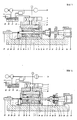
- a feed piston (3) is arranged in a one-piece housing (1) concentrically with a working piston (2), Figure 1.
- the area of the feed piston (3) is several times the area of the working piston (2).
- the working piston (2) which is much smaller than the housing bore, which corresponds to the diameter of the feed piston (3), is with its front Piston rod (8) in the front housing cover (12), and with its rear piston rod (14) in the rear housing cover (13).
- a clamping head (10) is clamped to the sample (11) on both sides.
- the clamping heads (10) are connected on one side to the front piston rod (8) and on the other side to the force sensor (25) via plug connections (9).
- the force sensor is attached to the frame (24).
- the servo valve (5) is attached to the housing (1). It is connected by line (28) to the front space (34) of the housing bore and by line (29) to the rear space (35) of the housing bore.
- An adjustable throttle (4) is arranged in the line (29) through which the oil displaced by the feed piston (3) flows out during the test process.
- the servo valve (5) opens the connection P to B and A to T.
- the oil flowing from the accumulator (30) in the space (34) moves the feed piston (3) towards the working piston (2) and accelerates until it reaches a speed specified by the setting of the throttle (4).
- the feed piston (3) has on its side facing the working piston (2) a pressure chamber (7) into which the working piston (2) is fitted with minimal play.
- the working piston (2) blocks the pressure chamber (7) in which an oil cushion is formed.
- the working piston (2) now floats on this oil cushion and is carried by the feed piston (3).
- the sample (11) is stretched and torn. While the feed piston (3) runs through the acceleration section (6), the displaced oil must flow around the working piston (2).
- the pressure acting on the working piston in the pressure chamber corresponds to the usual pressures in servo-hydraulic testing machines.
- the force to be applied to accelerate the working piston (2) and to withdraw the sample (11) from the feed piston (3) brakes the feed piston. This reduces the pressure drop between the accumulator (30) and the space (34), ie the pressure on this side of the feed piston (3) increases.
- the pressure drop between space (35) and throttle (4) to tank (31) is reduced, ie the pressure on the side of the feed piston facing the working piston (2) drops.
- the pressure required to overcome the flow resistances is proportional to the flow velocity in a square.
- a slight reduction in the speed of the feed piston (3) and thus the flow rate in the system is therefore sufficient to generate a pressure difference on the feed piston which is sufficient to accelerate the working piston and to stretch the sample until it breaks.
- the reduction in the speed of the feed piston is less than the permissible tolerance of the test speed.
- the system is self-regulating due to this design, the large area of the feed piston (3) and the throttle (4) in the drain, which has the most significant part in the pressure difference building up and down on the feed piston.
- the front piston rod (8) is provided at its end with a steep taper (15), which is used to hold the clamping bell (17) with the sample (18), and a disc (16) is mounted on the rear piston rod (14) , Figure 2.
- the working piston (2) is now arranged between the front housing cover (12) and the feed piston (3), and the throttle (4) lies in the line (28).
- a counter cylinder (19) is arranged on the frame (24) such that its axis is aligned with the axis of the working piston (2).
- the piercing body (21) is attached to its piston rod (20).
- the force sensor (25) is arranged behind the hemispherical tip of the piercing body, in accordance with the requirements of DIN 53 443.
- the wiper (22) is located between the counter-cylinder (19) and the housing (1).
- P is connected to B and A to T in the servo valve (5), the feed piston (3) presses the disc (16) against the rear housing cover (13), and the end of the rear piston rod (14) against the spring (23). Since the axis of the puncture testing machine is arranged vertically, the clamping bell (17) can simply be placed on the non-self-holding steep taper (15) of the front piston rod (8) without any further fastening elements. she can This means that it can be easily inserted and removed from the testing machine with one hand and without tools. This is important for temperature-controlled samples.
- a plurality of clamping bells are expediently used, into which the disk-shaped puncture samples (18) are clamped outside the testing machine. These tension bells are brought to the required temperature in a separate temperature control chamber. When the bell and sample have reached the temperature, the bell with the sample is removed from the temperature control chamber and placed on the steep taper (15) of the piston rod (8) and the sample is pierced. A maximum of 5 seconds elapse between removal from the temperature control chamber and puncturing. This ensures that the sample, which is largely shielded from room temperature by the clamping bell, remains at its temperature until it is pierced.
- a puncture test has the following sequence: A clamping bell (17) with sample (18) is placed on the steep taper (15) of the piston rod (8), and the control is started via a two-hand safety device.
- the piston rod (20) of the counter cylinder (19) moves forward until the tip of the piercing body (21) is approx. 1-2 mm in front of the surface of the sample (18), Figure 3.
- P in the servo valve (5) with A and B connected to T As a result, the feed piston (3) is moved in the direction of the working piston (2) and the disc (16) is released.
- the very light working piston (2) with piston rods (8 + 14) and the likewise very light clamping bell (17) with sample (18) are opened in a fraction of a millisecond accelerates the same speed as the feed piston (3), thereby piercing the sample.
- the clamping bell with the sample is pushed over the piercing body until the clamping bell hits the stripper (22), which is made of an elastic material, Figure 4.
- the distance that the clamping bell travels is measured with the displacement transducer (27) .
- the counter-cylinder (19) then pulls the puncture body (21) back, and a tough sample that may adhere to the puncture body is stripped off.
- the servo valve (5) reverses and the feed piston (3) pushes the working piston with piston rods and clamping bell back into the starting positions via the disc (16), Figure 2.
Landscapes
- Physics & Mathematics (AREA)
- Health & Medical Sciences (AREA)
- Life Sciences & Earth Sciences (AREA)
- Chemical & Material Sciences (AREA)
- Analytical Chemistry (AREA)
- Biochemistry (AREA)
- General Health & Medical Sciences (AREA)
- General Physics & Mathematics (AREA)
- Immunology (AREA)
- Pathology (AREA)
- Investigating Strength Of Materials By Application Of Mechanical Stress (AREA)
Applications Claiming Priority (2)
| Application Number | Priority Date | Filing Date | Title |
|---|---|---|---|
| DE3802500 | 1988-01-28 | ||
| DE3802500A DE3802500C1 (fr) | 1988-01-28 | 1988-01-28 |
Publications (2)
| Publication Number | Publication Date |
|---|---|
| EP0326070A2 true EP0326070A2 (fr) | 1989-08-02 |
| EP0326070A3 EP0326070A3 (fr) | 1990-09-12 |
Family
ID=6346162
Family Applications (1)
| Application Number | Title | Priority Date | Filing Date |
|---|---|---|---|
| EP19890101171 Withdrawn EP0326070A3 (fr) | 1988-01-28 | 1989-01-24 | Dispositif hydraulique d'entraínement pour essais de tension et de perçage de type impulsionnel |
Country Status (3)
| Country | Link |
|---|---|
| US (1) | US4930355A (fr) |
| EP (1) | EP0326070A3 (fr) |
| DE (1) | DE3802500C1 (fr) |
Cited By (1)
| Publication number | Priority date | Publication date | Assignee | Title |
|---|---|---|---|---|
| EP0500982A1 (fr) * | 1991-02-28 | 1992-09-02 | Carl Schenck Ag | Dispositif d'essai pour soumettre un échantillon à charges mécaniques |
Families Citing this family (23)
| Publication number | Priority date | Publication date | Assignee | Title |
|---|---|---|---|---|
| US5473928A (en) * | 1994-04-15 | 1995-12-12 | Teitzel; Frederick E. | Tool and method for straightening a panel |
| DE10049833B4 (de) * | 2000-10-09 | 2004-07-15 | IFF Prof. Dr. Habenicht Institut für Fügetechnische Fertigungsverfahren GmbH | Temperiervorrichtung, insbesondere für eine Werkstoffprüfvorrichtung sowie Werkstoffprüfverfahren |
| RU2189025C1 (ru) * | 2001-01-11 | 2002-09-10 | Кондращенко Валерий Иванович | Устройство для испытания образцов на прочность |
| US6955093B2 (en) | 2001-10-16 | 2005-10-18 | Microflex Corporation | Rupture testing for gloves |
| FR2858055B1 (fr) * | 2003-07-23 | 2005-11-25 | Nantes Ecole Centrale | Banc d'essai universel destine a la caracterisation des lois de comportement statique et dynamique de tous materiaux |
| US20060198486A1 (en) * | 2005-03-04 | 2006-09-07 | Laberge Michel G | Pressure wave generator and controller for generating a pressure wave in a fusion reactor |
| US7412870B2 (en) * | 2005-12-02 | 2008-08-19 | California Micro Devices | Method and apparatus for dynamic impact testing |
| DE102007010426B4 (de) * | 2007-03-01 | 2008-11-13 | Ortwin Prof. Dr.-Ing. Hahn | Prüfvorrichtung für Proben unter Stoßbelastung |
| DE102007012492B4 (de) * | 2007-03-15 | 2017-11-23 | Illinois Tool Works Inc. | Vorrichtung zur Durchführung von Crash-Versuchen |
| US7533557B1 (en) | 2007-12-18 | 2009-05-19 | The United States Of America As Represented By The Secretary Of The Navy | Impact tensile test machine |
| US8537958B2 (en) | 2009-02-04 | 2013-09-17 | General Fusion, Inc. | Systems and methods for compressing plasma |
| BR112012002147B1 (pt) | 2009-07-29 | 2020-12-22 | General Fusion, Inc | sistemas e métodos para compressão de plasma com reciclagem de projéteis |
| CN103384561B (zh) | 2011-02-25 | 2015-11-25 | 全面熔合有限公司 | 用于在介质中产生压力波的具有可移动的控制杆的压力波发生器 |
| CN102393295A (zh) * | 2011-09-08 | 2012-03-28 | 浙江九隆机械有限公司 | 一种制动器的测试装置 |
| CN102435500B (zh) * | 2011-12-15 | 2013-06-19 | 五邑大学 | 一种摩托车车架水平刚度性能测试装置 |
| EP2953734B1 (fr) | 2013-02-08 | 2020-08-26 | General Fusion Inc. | Générateur d'ondes de pression doté d'un piston lancé par sabot et méthode de génération d'une onde de pression |
| CN103323164B (zh) * | 2013-06-28 | 2014-12-10 | 东北大学 | 一种测量静态破碎剂膨胀压的测试系统及测试方法 |
| KR101665965B1 (ko) * | 2014-08-08 | 2016-10-14 | 코리아테스팅 주식회사 | 충돌시험용 하이브리드 서보 액추에이터 |
| CN110410384B (zh) * | 2019-09-01 | 2024-03-08 | 宋彦宏 | 一种液压管路的来油测量指示仪及检测方法 |
| CN111707469B (zh) * | 2020-06-24 | 2022-06-14 | 中国航发中传机械有限公司 | 一种直升机尾减速器操纵轴力加载试验装置 |
| CN113043651A (zh) * | 2021-03-30 | 2021-06-29 | 浙江德瑞新材科技股份有限公司 | 一种摩擦片热压机加温系统及使用方法 |
| CN113340734B (zh) * | 2021-06-11 | 2022-05-17 | 湖北中烟工业有限责任公司 | 一种烟叶穿透强度的测定装置 |
| CN120404371B (zh) * | 2025-07-07 | 2025-09-09 | 金言实业集团有限公司 | 一种铝塑板用高效强度检测装置 |
Family Cites Families (10)
| Publication number | Priority date | Publication date | Assignee | Title |
|---|---|---|---|---|
| GB190619966A (en) * | 1906-09-07 | 1907-06-20 | William David Edwards | Improvements in Hydrostatic Paper Testing Machines. |
| DE610736C (de) * | 1932-05-31 | 1935-03-15 | Schmidt Wolfgang | Vorrichtung zum Auffangen der Rueckstoesse bei Pressluftwerkzeugen und -maschinen |
| US3631760A (en) * | 1969-12-05 | 1972-01-04 | Us Navy | Pneumatic torpedo launcher with hydraulic operated snubber |
| SU397794A1 (ru) * | 1972-04-10 | 1973-09-17 | УСТРОЙСТВО дл ПРОКОЛА ДИАФРАГМЫ ГАЗОДИНАМИЧЕСКОЙ УДАРНОЙ ТРУБЫ | |
| US3973468A (en) * | 1973-11-21 | 1976-08-10 | Russell Jr Wayne B | Multi-stage extendible and contractible shaft with shock absorption |
| SU777542A1 (ru) * | 1978-12-11 | 1980-11-07 | Чебоксарский Завод Промышленных Тракторов | Устройство дл испытани образцов на раст жение |
| EP0079979B1 (fr) * | 1981-11-24 | 1986-03-26 | Carl Schenck Ag | Dispositif hydraulique de mise en charge, en particulier pour systèmes à catapulte |
| DE3334813A1 (de) * | 1983-09-26 | 1985-04-11 | Brown, Boveri & Cie Ag, 6800 Mannheim | Hochdruckspeicher |
| IT1187318B (it) * | 1985-02-22 | 1987-12-23 | Franco Zanarini | Compressore volumetrico alternato ad azionamento idraulico |
| DE3529470A1 (de) * | 1985-08-16 | 1986-01-02 | Siegfried 7032 Sindelfingen Heck | Schlagzug-pruefmaschine zur schlagartigen beanspruchung von zugproben, vorzugsweise aus kunststoffen |
-
1988
- 1988-01-28 DE DE3802500A patent/DE3802500C1/de not_active Expired
-
1989
- 1989-01-24 EP EP19890101171 patent/EP0326070A3/fr not_active Withdrawn
- 1989-01-30 US US07/305,895 patent/US4930355A/en not_active Expired - Fee Related
Cited By (1)
| Publication number | Priority date | Publication date | Assignee | Title |
|---|---|---|---|---|
| EP0500982A1 (fr) * | 1991-02-28 | 1992-09-02 | Carl Schenck Ag | Dispositif d'essai pour soumettre un échantillon à charges mécaniques |
Also Published As
| Publication number | Publication date |
|---|---|
| US4930355A (en) | 1990-06-05 |
| DE3802500C1 (fr) | 1989-06-22 |
| EP0326070A3 (fr) | 1990-09-12 |
Similar Documents
| Publication | Publication Date | Title |
|---|---|---|
| DE3802500C1 (fr) | ||
| DE69211092T2 (de) | Vorrichtung und Verfahren zur Prüfung der mechanischen Beansprachbarkeit eines Materials | |
| DE102015013401B3 (de) | Vorrichtung und Verfahren zur Kalibrierung und/oder Justage von Messeinrichtungen für dynamische Kräfte | |
| DE2928153A1 (de) | Bremsentestvorrichtung | |
| AT521555A1 (de) | Plattensäge | |
| EP3771505B1 (fr) | Procédé de commande d'un processus mécanique d'assemblage | |
| EP0354250B1 (fr) | Appareil d'essais de perforation pour échantillons de matériau ou pour pièces détachées | |
| DE102006002237B4 (de) | Verfahren und Vorrichtung zum Überwachen eines Fügeprozesses zum Verbinden mindestens zweier Bauteile mittels eines Setzbolzens | |
| DE3012977A1 (de) | Materialpruefvorrichtung | |
| DE4420942C2 (de) | Ölkontrollsystem für eine mechanische Presse | |
| DE102007010426B4 (de) | Prüfvorrichtung für Proben unter Stoßbelastung | |
| DE102010006403A1 (de) | Verfahren zum Überwachen eines Hochgeschwindigkeits-Fügeprozesses | |
| DE3939189C2 (fr) | ||
| EP3983190A1 (fr) | Dispositif pour la préparation et le traitement d'un mélange à plusieurs composants et procédé pour faire fonctionner un tel dispositif | |
| EP2036626B1 (fr) | Dispositif de perforation | |
| EP0314829B1 (fr) | Machine d'essai rapide de traction | |
| DE3529470C2 (fr) | ||
| EP2054177B1 (fr) | Procédé et dispositif d'amortissement des percussions de coupe | |
| DE102016207697B4 (de) | Verfahren zum Verbinden wenigstens zweier Bauteile mittels einer Stanznietvorrichtung, Stanznietvorrichtung und Fertigungseinrichtung | |
| DE102019112001B4 (de) | Überlastschutzeinrichtung für Handhabungsgeräte | |
| DE10312868B4 (de) | Abfragevorrichtung, pneumatisches Handhabungsgerät und Verfahren hierfür | |
| DE102006015581B3 (de) | Verfahren und Vorrichtung zur Durchführung eines Umformprozesses | |
| DE10049846B4 (de) | Prüfvorrichtung | |
| DE3733643C2 (fr) | ||
| DD235219A1 (de) | Greifwerkzeug fuer einen montageroboter |
Legal Events
| Date | Code | Title | Description |
|---|---|---|---|
| PUAI | Public reference made under article 153(3) epc to a published international application that has entered the european phase |
Free format text: ORIGINAL CODE: 0009012 |
|
| AK | Designated contracting states |
Kind code of ref document: A2 Designated state(s): DE FR GB IT |
|
| PUAL | Search report despatched |
Free format text: ORIGINAL CODE: 0009013 |
|
| AK | Designated contracting states |
Kind code of ref document: A3 Designated state(s): DE FR GB IT |
|
| 17P | Request for examination filed |
Effective date: 19901105 |
|
| 17Q | First examination report despatched |
Effective date: 19930115 |
|
| RAP1 | Party data changed (applicant data changed or rights of an application transferred) |
Owner name: POLY ID AG |
|
| STAA | Information on the status of an ep patent application or granted ep patent |
Free format text: STATUS: THE APPLICATION HAS BEEN WITHDRAWN |
|
| 18W | Application withdrawn |
Withdrawal date: 19930727 |