EP0326281A2 - Wechselrichtereinrichtung für Automobilwechselstromgenerator - Google Patents
Wechselrichtereinrichtung für Automobilwechselstromgenerator Download PDFInfo
- Publication number
- EP0326281A2 EP0326281A2 EP89300453A EP89300453A EP0326281A2 EP 0326281 A2 EP0326281 A2 EP 0326281A2 EP 89300453 A EP89300453 A EP 89300453A EP 89300453 A EP89300453 A EP 89300453A EP 0326281 A2 EP0326281 A2 EP 0326281A2
- Authority
- EP
- European Patent Office
- Prior art keywords
- diodes
- full
- semiconductor diodes
- coupled
- armature coils
- Prior art date
- Legal status (The legal status is an assumption and is not a legal conclusion. Google has not performed a legal analysis and makes no representation as to the accuracy of the status listed.)
- Granted
Links
Images




Classifications
-
- H—ELECTRICITY
- H02—GENERATION; CONVERSION OR DISTRIBUTION OF ELECTRIC POWER
- H02M—APPARATUS FOR CONVERSION BETWEEN AC AND AC, BETWEEN AC AND DC, OR BETWEEN DC AND DC, AND FOR USE WITH MAINS OR SIMILAR POWER SUPPLY SYSTEMS; CONVERSION OF DC OR AC INPUT POWER INTO SURGE OUTPUT POWER; CONTROL OR REGULATION THEREOF
- H02M7/00—Conversion of AC power input into DC power output; Conversion of DC power input into AC power output
- H02M7/02—Conversion of AC power input into DC power output without possibility of reversal
- H02M7/04—Conversion of AC power input into DC power output without possibility of reversal by static converters
- H02M7/06—Conversion of AC power input into DC power output without possibility of reversal by static converters using discharge tubes without control electrode or semiconductor devices without control electrode
- H02M7/08—Conversion of AC power input into DC power output without possibility of reversal by static converters using discharge tubes without control electrode or semiconductor devices without control electrode arranged for operation in parallel
Definitions
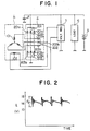
- the output voltage E of the rectifier device 2 comprises high frequency damped oscillation components, and the commutation surge voltage, or the peak-to-peak amplitude Ep of oscillations of the waveform, is as great as 6 volts.
- Fig. 3 shows another typical conventional rectifier device for the AC generator of an automobile.
- the rectifer device of Fig. 3 comprises, in addition to the diodes shown in Fig. 1, a pair of diodes 201d and 203d connected in series, wherein the neutral point of the armature coils 101 in Y-connection is connected to the intermediate point between these diodes 201d and 203d.
- damped oscillations in the output DC voltage of the rectifier divice 2 occur, not only when the diodes 201a through 201c and 203a through 203c go from the conducting to the reverse blocking state, but also when the neutral point diodes 201d and 203d go from the conducting to the reverse blocking state.
- a rectifier device for an AC generator in which the semiconductor rectifier diodes constituting the full-wave rectifier circuit are of the high speed switching type having the reverse recovery time of not more than 2 microseconds.
- a three-phase AC generator 2 of an automobile includes a stator having armature coils 101 connected in Y-connection, and a rotor having a field coil 102.
- the field coil 101 is rotated by the engine of the automobile, three phase voltages are induced in the armature coils 101.
- the three line output terminals of the armature coils 101 in Y-connection are coupled to the intermediate points between diodes 201a and 203a, 201b and 203b, and 201c and 203c, respectively.
- semiconductor diodes 202a through 202c of the auxiliary group 202 are coupled across these intermediate points and the auxiliary positive terminal of the rectifier device 2, the forward direction thereof being directed toward the positive auxiliary terminal.
- the rectifier device 2 rectifies the three line output voltages of the armature coils 101 in Y-connection, and outputs a DC voltage across the main positive and the negative and across the auxiliary positive and the negative terminal thereof.
- a capacitor 4 is coupled across the main positive and the negative terminal of the rectifier 2 to smooth the DC output thereof.
- the capacitance of the capacitor 4 may be 0.5 microfarads.
- electrical load 6 consisting of electrical equipment of the automobile, and battery 5 are coupled across the main positive and the negative terminal of the rectifier device 2.
- the voltage regulator 3 having inputs coupled across the main positive and the negative output terminal of the rectifier divice 2 controls the field current supplied to the field coil 102 to regulate the output DC voltage of the rectifier device to a predetermined level, i.e., 14.4 volts (rms).
- the fundamental period of the output voltage waveform depends on the rotational speed of the field coil 102: it is equal to one sixth (1/6) of the rotational period of the field coil 102 in which the rotor carrying the field coil 102 completes one rotation.
- the amplitude Ep of oscillations in the output voltage E is about 2 volts, and the waveform of the output voltage E is very near to that of an ideal rectifier device constitued by ideal diodes having zero reverse recovery time and zero reverse recovery current.
- the reverse recovery time of the auxiliary diodes 202a through 202c is about microseconds.
- the oscillations in the output voltage across the auxiliary positive and the negative terminal caused by the reverse recovery currents in the auxiliary diodes 202a through 202c do not affect the performance of the electrical equipment 6.
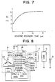
- Fig. 7 shows the relationship between the reverse recovery time of the rectifier diodes 201a through 201c and 203a through 203c (taken along the abscissa in microseconds) and the amplitude Ep of oscillations in the output voltage E (taken along the ordinate in volts).
- the oscillation amplitude Ep is limited under 3 volts if the reverse recovery time is not more than 2 microseconds, which is the preferred upper limit thereof according to this invention.
- commonly used semiconductor rectifier diodes have a reverse recovery time of about from 10 to 30 microseconds.
- Fig. 8 of the drawings a second embodiment according to this invention is described.
- the circuit of Fig. 8 is similar to that of Fig. 5, except for the provision of semiconductor diodes 201d and 203d for rectifying the three phase voltages induced in the armature coils 101 in cooperation with diodes 201a through 201c and 203a through 203c.
- series circuit of diodes 201d and 203d having the same reverse recovery time as diodes 201a through 201c and 203a through 203c is coupled across the main positive and the negative terminal of the rectifier device 2, the forward direction of the diodes 201d and 203d being directed toward the positive terminal.
- the neutral point of the Y-connected armature coils 101 is coupled to an intermediate point between the two diodes 201d and 203d.
- the waveform of the output voltage E across the main positive and the negative terminal of the rectifier device 2 of Fig. 8 contains little damped oscillation components; the oscillation amplitude Ep in the waveform of the output voltage E is about 3 volts.
Landscapes
- Engineering & Computer Science (AREA)
- Power Engineering (AREA)
- Rectifiers (AREA)
- Control Of Eletrric Generators (AREA)
- Control Of Charge By Means Of Generators (AREA)
Applications Claiming Priority (2)
| Application Number | Priority Date | Filing Date | Title |
|---|---|---|---|
| JP8421/88 | 1988-01-25 | ||
| JP842188U JPH01113587U (de) | 1988-01-25 | 1988-01-25 |
Publications (3)
| Publication Number | Publication Date |
|---|---|
| EP0326281A2 true EP0326281A2 (de) | 1989-08-02 |
| EP0326281A3 EP0326281A3 (en) | 1990-03-28 |
| EP0326281B1 EP0326281B1 (de) | 1994-04-13 |
Family
ID=11692662
Family Applications (1)
| Application Number | Title | Priority Date | Filing Date |
|---|---|---|---|
| EP19890300453 Expired - Lifetime EP0326281B1 (de) | 1988-01-25 | 1989-01-18 | Wechselrichtereinrichtung für Automobilwechselstromgenerator |
Country Status (3)
| Country | Link |
|---|---|
| EP (1) | EP0326281B1 (de) |
| JP (1) | JPH01113587U (de) |
| DE (1) | DE68914481T2 (de) |
Cited By (1)
| Publication number | Priority date | Publication date | Assignee | Title |
|---|---|---|---|---|
| WO2003012967A1 (en) * | 2001-07-31 | 2003-02-13 | Ge Power Controls Iberica S.L. | Neutral pole location independent earth leakage detection circuit |
Family Cites Families (5)
| Publication number | Priority date | Publication date | Assignee | Title |
|---|---|---|---|---|
| US3641374A (en) * | 1970-03-11 | 1972-02-08 | Nippon Denso Co | Rectifying means for three-phase alternating generators for use in vehicles and other transport facilities |
| US4489374A (en) * | 1981-09-21 | 1984-12-18 | Mitsubishi Denki Kabushiki Kaisha | Rectifying apparatus for automotive A.C. generator |
| JPS5970185A (ja) * | 1982-10-14 | 1984-04-20 | Toshiba Corp | 電力変換装置 |
| FR2576164B1 (fr) * | 1985-01-15 | 1987-02-20 | Thomson Csf | Circuit de commutation utilisant une diode rapide et pourvu de moyens d'amortissement des oscillations a l'ouverture |
| JPS6281983A (ja) * | 1985-10-02 | 1987-04-15 | Hitachi Ltd | 電流形インバ−タ−の主回路 |
-
1988
- 1988-01-25 JP JP842188U patent/JPH01113587U/ja active Pending
-
1989
- 1989-01-18 DE DE1989614481 patent/DE68914481T2/de not_active Expired - Fee Related
- 1989-01-18 EP EP19890300453 patent/EP0326281B1/de not_active Expired - Lifetime
Cited By (1)
| Publication number | Priority date | Publication date | Assignee | Title |
|---|---|---|---|---|
| WO2003012967A1 (en) * | 2001-07-31 | 2003-02-13 | Ge Power Controls Iberica S.L. | Neutral pole location independent earth leakage detection circuit |
Also Published As
| Publication number | Publication date |
|---|---|
| JPH01113587U (de) | 1989-07-31 |
| EP0326281B1 (de) | 1994-04-13 |
| DE68914481T2 (de) | 1994-08-04 |
| EP0326281A3 (en) | 1990-03-28 |
| DE68914481D1 (de) | 1994-05-19 |
Similar Documents
| Publication | Publication Date | Title |
|---|---|---|
| US4686442A (en) | Dual voltage electrical system | |
| US5694027A (en) | Three-phase brushless self-excited synchronous generator with no rotor excitation windings | |
| US5444355A (en) | Charging generator for a vehicle | |
| US6069431A (en) | Synchronous generator | |
| US4948209A (en) | VSCF starter/generator systems | |
| US3694731A (en) | Multiple mode vehicle power supply system | |
| US7414331B2 (en) | Power converter system and method | |
| US4340849A (en) | Ripple-compensated voltage regulator, particularly for automotive use | |
| EP0406182A1 (de) | Elektrische Generator-Anlasservorrichtung, insbesondere zur Anwendung als Generator und Anlasser für Kraftfahrzeuge | |
| US6066941A (en) | Switching alternator system | |
| US6195276B1 (en) | Controller for a Graetz switch bridge rectifier for an alternator | |
| EP1993198A1 (de) | Ausgangsspannungssteuerung eines wechselstromgenerators für ein fahrzeug | |
| US6359800B1 (en) | Direct current electric power generation system with variable speed alternating current generators | |
| EP0326281B1 (de) | Wechselrichtereinrichtung für Automobilwechselstromgenerator | |
| US6831445B2 (en) | Automotive alternator having parallel connected circulating circuit to rapidly attenuate field current | |
| JPH0161026B2 (de) | ||
| JP3161241B2 (ja) | 内燃機関用電源装置 | |
| US4982316A (en) | Polyphase full-wave rectifying circuit | |
| KR100216015B1 (ko) | 교류발전기의출력전압제어장치 | |
| EP3343745B1 (de) | Wechselrichter-generator-vorrichtung | |
| JP3681050B2 (ja) | 磁石発電機を用いた電源装置 | |
| US4395673A (en) | Controlled rectifier motor vehicle battery charger | |
| US5444357A (en) | Method and apparatus for three-phase voltage doubling | |
| CA1268518A (en) | Power generator | |
| JPH0229831Y2 (de) |
Legal Events
| Date | Code | Title | Description |
|---|---|---|---|
| PUAI | Public reference made under article 153(3) epc to a published international application that has entered the european phase |
Free format text: ORIGINAL CODE: 0009012 |
|
| AK | Designated contracting states |
Kind code of ref document: A2 Designated state(s): DE FR GB IT |
|
| PUAL | Search report despatched |
Free format text: ORIGINAL CODE: 0009013 |
|
| RHK1 | Main classification (correction) |
Ipc: H02M 7/06 |
|
| AK | Designated contracting states |
Kind code of ref document: A3 Designated state(s): DE FR GB IT |
|
| 17P | Request for examination filed |
Effective date: 19900608 |
|
| ITF | It: translation for a ep patent filed | ||
| 17Q | First examination report despatched |
Effective date: 19920520 |
|
| GRAA | (expected) grant |
Free format text: ORIGINAL CODE: 0009210 |
|
| AK | Designated contracting states |
Kind code of ref document: B1 Designated state(s): DE FR GB IT |
|
| ITF | It: translation for a ep patent filed | ||
| REF | Corresponds to: |
Ref document number: 68914481 Country of ref document: DE Date of ref document: 19940519 |
|
| REG | Reference to a national code |
Ref country code: GB Ref legal event code: 727 |
|
| REG | Reference to a national code |
Ref country code: GB Ref legal event code: 727A |
|
| ET | Fr: translation filed | ||
| REG | Reference to a national code |
Ref country code: GB Ref legal event code: 727B |
|
| REG | Reference to a national code |
Ref country code: GB Ref legal event code: SP |
|
| PLBE | No opposition filed within time limit |
Free format text: ORIGINAL CODE: 0009261 |
|
| STAA | Information on the status of an ep patent application or granted ep patent |
Free format text: STATUS: NO OPPOSITION FILED WITHIN TIME LIMIT |
|
| 26N | No opposition filed | ||
| REG | Reference to a national code |
Ref country code: GB Ref legal event code: 746 Effective date: 19951026 |
|
| REG | Reference to a national code |
Ref country code: FR Ref legal event code: D6 |
|
| PGFP | Annual fee paid to national office [announced via postgrant information from national office to epo] |
Ref country code: FR Payment date: 19990111 Year of fee payment: 11 |
|
| PGFP | Annual fee paid to national office [announced via postgrant information from national office to epo] |
Ref country code: GB Payment date: 19990121 Year of fee payment: 11 |
|
| PGFP | Annual fee paid to national office [announced via postgrant information from national office to epo] |
Ref country code: DE Payment date: 19990125 Year of fee payment: 11 |
|
| PG25 | Lapsed in a contracting state [announced via postgrant information from national office to epo] |
Ref country code: GB Free format text: LAPSE BECAUSE OF NON-PAYMENT OF DUE FEES Effective date: 20000118 |
|
| GBPC | Gb: european patent ceased through non-payment of renewal fee |
Effective date: 20000118 |
|
| PG25 | Lapsed in a contracting state [announced via postgrant information from national office to epo] |
Ref country code: FR Free format text: LAPSE BECAUSE OF NON-PAYMENT OF DUE FEES Effective date: 20000929 |
|
| PG25 | Lapsed in a contracting state [announced via postgrant information from national office to epo] |
Ref country code: DE Free format text: LAPSE BECAUSE OF NON-PAYMENT OF DUE FEES Effective date: 20001101 |
|
| REG | Reference to a national code |
Ref country code: FR Ref legal event code: ST |
|
| PG25 | Lapsed in a contracting state [announced via postgrant information from national office to epo] |
Ref country code: IT Free format text: LAPSE BECAUSE OF NON-PAYMENT OF DUE FEES;WARNING: LAPSES OF ITALIAN PATENTS WITH EFFECTIVE DATE BEFORE 2007 MAY HAVE OCCURRED AT ANY TIME BEFORE 2007. THE CORRECT EFFECTIVE DATE MAY BE DIFFERENT FROM THE ONE RECORDED. Effective date: 20050118 |