EP0326332A2 - Procédé pour mettre en oeuvre un moteur alternatif avec des convertisseurs à courant de circulation connectés en parallèle - Google Patents
Procédé pour mettre en oeuvre un moteur alternatif avec des convertisseurs à courant de circulation connectés en parallèle Download PDFInfo
- Publication number
- EP0326332A2 EP0326332A2 EP89300662A EP89300662A EP0326332A2 EP 0326332 A2 EP0326332 A2 EP 0326332A2 EP 89300662 A EP89300662 A EP 89300662A EP 89300662 A EP89300662 A EP 89300662A EP 0326332 A2 EP0326332 A2 EP 0326332A2
- Authority
- EP
- European Patent Office
- Prior art keywords
- load
- converters
- power converters
- currents
- phase
- Prior art date
- Legal status (The legal status is an assumption and is not a legal conclusion. Google has not performed a legal analysis and makes no representation as to the accuracy of the status listed.)
- Withdrawn
Links
Images


Classifications
-
- H—ELECTRICITY
- H02—GENERATION; CONVERSION OR DISTRIBUTION OF ELECTRIC POWER
- H02M—APPARATUS FOR CONVERSION BETWEEN AC AND AC, BETWEEN AC AND DC, OR BETWEEN DC AND DC, AND FOR USE WITH MAINS OR SIMILAR POWER SUPPLY SYSTEMS; CONVERSION OF DC OR AC INPUT POWER INTO SURGE OUTPUT POWER; CONTROL OR REGULATION THEREOF
- H02M5/00—Conversion of AC power input into AC power output, e.g. for change of voltage, for change of frequency, for change of number of phases
- H02M5/40—Conversion of AC power input into AC power output, e.g. for change of voltage, for change of frequency, for change of number of phases with intermediate conversion into DC
- H02M5/42—Conversion of AC power input into AC power output, e.g. for change of voltage, for change of frequency, for change of number of phases with intermediate conversion into DC by static converters
- H02M5/44—Conversion of AC power input into AC power output, e.g. for change of voltage, for change of frequency, for change of number of phases with intermediate conversion into DC by static converters using discharge tubes or semiconductor devices to convert the intermediate DC into AC
- H02M5/443—Conversion of AC power input into AC power output, e.g. for change of voltage, for change of frequency, for change of number of phases with intermediate conversion into DC by static converters using discharge tubes or semiconductor devices to convert the intermediate DC into AC using devices of a thyratron or thyristor type requiring extinguishing means
- H02M5/45—Conversion of AC power input into AC power output, e.g. for change of voltage, for change of frequency, for change of number of phases with intermediate conversion into DC by static converters using discharge tubes or semiconductor devices to convert the intermediate DC into AC using devices of a thyratron or thyristor type requiring extinguishing means using semiconductor devices only
- H02M5/4505—Conversion of AC power input into AC power output, e.g. for change of voltage, for change of frequency, for change of number of phases with intermediate conversion into DC by static converters using discharge tubes or semiconductor devices to convert the intermediate DC into AC using devices of a thyratron or thyristor type requiring extinguishing means using semiconductor devices only having a rectifier with controlled elements
-
- H—ELECTRICITY
- H02—GENERATION; CONVERSION OR DISTRIBUTION OF ELECTRIC POWER
- H02P—CONTROL OR REGULATION OF ELECTRIC MOTORS, ELECTRIC GENERATORS OR DYNAMO-ELECTRIC CONVERTERS; CONTROLLING TRANSFORMERS, REACTORS OR CHOKE COILS
- H02P2201/00—Indexing scheme relating to controlling arrangements characterised by the converter used
- H02P2201/13—DC-link of current link type, e.g. typically for thyristor bridges, having an inductor in series with rectifier
Definitions
- This invention is directed to a method of operating in the load commutated mode an ac drive comprising parallel connected polyphase dc link power converters. More particularly, it is directed to firing load commutated controlled rectifier switches in polyphase output inverters of the power converters in a sequence which generates from constant dc link currents in the power converters, polyphase, alternating load currents from each inverter which are phase shifted relative to one another by an amount which reduces selected harmonics in the composite load current.
- Variable speed ac drives of the load commutated inverted (LCI) type utilize a dc link power converter to convert line current of a given frequency to a load current of a controlled, variable frequency.
- a power converter includes an inverter to generate the load current of variable frequency from the dc current generated by a line side rectifier.
- these inverters employ thyristors to gate portions of the dc current to the load. Switches such as thyristors can not be turned off from the control electrode, but must be commutated by other means.
- the LCI type drive is used with an over excited synchronous motor which presents a leading power factor to the inverter thyristors to allow the thyristors to operate as naturally commutated switches. At standstill or very low speeds, however, the motor voltages are insufficient to effect this commutation and other means must be utilized.
- a solution to this problem has been to operate the power converter in a "pulsed mode" where the dc link current is periodically forced to zero by the line side converter to allow the motor side inverter thyristors to commutate.
- the pulse mode forces the current to be square in nature, with significant fifth and seventh harmonic components, which in turn give rise to strong torque pulsations at six times the line frequency and harmonics thereof for a three-phase drive.
- US-A-4,084,220 is directed to an ac drive designed to reduce these torque pulsations at low fundamental load frequencies. It calls for two dc link power converters connected in parallel. Shaped dc pulses are generated in the respective dc circuits of the two converters. The shaped dc pulse signals are phase shifted such that the resultant current gated to the load by the two load side inverters of the converters more closely approximates a sine-wave than a square wave. This system requires that the repetition rate of the pulsed dc signal be three times the fundamental frequency of the load current. As a result, it is only suitable for reducing torque pulsation at low frequencies. As frequency increases, the thyristors can not be switched rapidly enough to maintain a repetition rate of the pulsed dc which is three times that of the fundamental load frequency.
- the dual power converters of US-A-4,084,220 like systems with a single power converter, are operated in the load commutated mode with constant dc link currents at higher load frequencies, typically above about 12 Hz or so.
- the load currents generated by the output inverters are square in nature with the attendant problems discussed above.
- the switches of the output inverters of the dual converters are operated in parallel in the load commutated mode so that the same square waves and torque pulsations are generated with the dual converters as with a single power converter.
- the invention consists in a method of operating an ac drive comprising a plurality of parallel connected polyphase dc link power converters having load side converters with load commutated controlled rectifier switches which are cyclically fired to generate component alternating load currents which are summed by the parallel connection of said power converters to produce a composite load current, said method comprising: operating said dc link power converters to generate substantially constant dc link currents; and cyclically firing the controlled rectifier switches in said load side converters of the respective power converters at a repetition rate which effects load commutation between said controlled rectifier switches and generates from said substantially constant dc link currents, component alternating load currents which are phase shifted by an amount which reduces the magnitude of at least a selected harmonic in the composite load current.
- the switches in the output inverters of dual, parallel connected converters are cyclically fired to generate load currents which are phase shifted about 30 degrees with respect to one another to substantially reduce both the 5th and 7th harmonics in the composite load current.
- the controlled rectifier switches of the output inverter of one power converter can be shifted 36 degrees with respect to the other to completely eliminate the fifth harmonic in the composite load current, although this would result in an increase in the magnitude of the seventh harmonic.
- the ac drive 1 to which the invention is applied includes two, three-phase dc link power converters 2a and 2b.
- the dual power converters 2 are connected in parallel between a three-phase ac power supply 3 and a three-phase load 4, such as a synchronous motor.
- Each dc link power converter 2 includes a pair of line side converters, one positive 5P1,5P2 and one negative 5N1,5N2, a positive load side converter 6P1,6P2 and a negative load side converter 6N1, 6N2.
- the positive line side and load side converters, and similarly the negative line side and load side converters of each power converter 2 are linked by leads 7 and 8 respectively through which dc current circulates.
- Each of the converters 5 and 6 includes a controlled rectifier switch 9 for each phase of the ac current.
- these switches 9 are thyristors, although Thyratrons or Ignitrons, for example, could be used alternatively where load demands permit.
- single switches 9 are shown, two or more such switches may be used in series for each switch 9 shown in Figure 1 for driving large loads where higher voltages are required.
- the line side converters 5 provide full wave rectification of the three-phase line current when the motor 4 is being driven. Their switches 9 are cyclically fired to generate dc link currents i1, and i2 in the power converters 2. Reactors 10a and 10b in the respective leads 7 and 8 filter ripple in these dc link currents.
- the switches 9 of the load side converters 6 of the power converter 2 are cyclically fired to generate load currents of a desired frequency to control the speed of the synchronous motor 4.
- the constant frequency line current is converted to a variable frequency load current to control motor speed.
- the ac drive shown in Figure 1 is substantially the drive disclosed in US-A-4,084,220.
- the switches of the power converters cannot be operated rapidly enough to produce the desired waveforms.
- the switches 9 of the line side converters are operated to generate substantially constant dc link currents within the power converters, and the switches 9 of the load side converters are commutated by the (CEMF) of the load motor 4.
- the switches of the load 9 side converters of each of the power converters 2 in US-A-4,084,220 are cyclically fired in parallel so that identical in-phase six-pulse square wave output currents are generated.
- Such six-pulse currents generate torque pulsations due to the undesirably large current harmonics, especially fifth and seventh harmonics.
- the switches 9 of the load side converters 6 of the two parallel connected power converters 2 are not operated in parallel. Instead, the firing of the switches of the load side converters of one of the power converters is advanced with respect to the firing of the switches in the load side converters of the other power converter.
- the converter switches of one of the power converters can be gated with a 30 degree advance in the firing signals, which of course, provides a 30 degree phase lead to its contribution to the motor current.
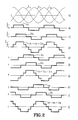
- Figure 2 illustrates the resultant waveforms for such a 30 degree phase shift between the firing angles of the inverter switches in the two power converters 2 of Figure 1.
- Figure 2a illustrates the ideal sine-wave three-phase load voltages E u , E v and E W .
- Figure 2b represents the component i ul of the alternating load current produced by the load side converters 6P1 and 6N1 at terminal U1 of the power converter 2a.
- Figure 2c shows the identical component alternating load current i u2 generated at the terminal U2, but advanced by a phase angle of 30 degrees with respect to the current i ul .
- Figures 2e, f and g illustrate the contributions of the two power converters to the V phase current i v applied to the motor 4 at terminal V, and similarly, Figures 2h, i and j show the corresponding currents for the current U w applied to the motor through the W terminal.
- Figure 3 shows the maximum speed and maximum power at which the control technique of the invention could be employed without oversizing the motor or the power converters.
- ⁇ is the margin angle for firing the load converter thyristors.
- the angle ⁇ is defined as 180- ⁇ ,where ⁇ is the phase angle delay of firing the thyristors.
- Figure 3 has been normalized to ⁇ for operation of the two converters in parallel so that the curves depicted indicate the reduction in maximum speed and maximum power attainable with a phase angle of 30 degrees between the currents generated by the two power converters.
- Trace A of Figure 3 represents the maximum power producing component of current available at various converter margin angles with the inverter switches of one power converter advanced 30 degrees with respect to the firing angles of the inverter in the other converter as a function of ⁇ .
- This maximum power of current is determined as follows:
- the penalties increase with increasing converter margin angles, but again, the thyristors of the two converters can be fired in parallel when greater speed or power is required.
- While the preferred shift in the firing angles of the controlled rectifiers in the dual output inverters is 30 degrees because this staggering of the component load currents substantially reduces the magnitude of both the fifth and seventh harmonics, the harmonics of greatest magnitude in the six-pulse composite load current, other phase shifts can be used. For instance, by advancing the firing angles of one output inverter 36 degrees with respect to the other, the fifth harmonic can be completely eliminated. This does, however, result in somewhat of an increase in the magnitude of the seventh harmonic. Also, with more than two power converters, the shift in the firing angles between successive converters does not have to be equal nor do the magnitudes of the dc link currents have to be the same.
- the phase shift and magnitude of each power converter channel may be controlled independently.
- the combination of the controlled rectifier switches in the load side converters of the power converters are preferably pulsed 12 times per cycle of the motor frequency when operated in accordance with the invention. This does not produce true twelve-pulse operation, since as indicated above harmonics remain in the composite load current. However, it can be designated as pseudo twelve-pulse operation in view of the firing rate of the inverter switches and the substantial reduction in motor current harmonics.
Landscapes
- Engineering & Computer Science (AREA)
- Power Engineering (AREA)
- Inverter Devices (AREA)
- Rectifiers (AREA)
- Ac-Ac Conversion (AREA)
Applications Claiming Priority (2)
| Application Number | Priority Date | Filing Date | Title |
|---|---|---|---|
| US07/147,404 US4849870A (en) | 1988-01-25 | 1988-01-25 | Method of operating a-c drive with parallel connected d-c link power converters |
| US147404 | 1988-01-25 |
Publications (2)
| Publication Number | Publication Date |
|---|---|
| EP0326332A2 true EP0326332A2 (fr) | 1989-08-02 |
| EP0326332A3 EP0326332A3 (fr) | 1990-02-28 |
Family
ID=22521447
Family Applications (1)
| Application Number | Title | Priority Date | Filing Date |
|---|---|---|---|
| EP89300662A Withdrawn EP0326332A3 (fr) | 1988-01-25 | 1989-01-25 | Procédé pour mettre en oeuvre un moteur alternatif avec des convertisseurs à courant de circulation connectés en parallèle |
Country Status (3)
| Country | Link |
|---|---|
| US (1) | US4849870A (fr) |
| EP (1) | EP0326332A3 (fr) |
| JP (1) | JPH01222664A (fr) |
Cited By (4)
| Publication number | Priority date | Publication date | Assignee | Title |
|---|---|---|---|---|
| EP0473257A3 (en) * | 1990-08-14 | 1992-09-02 | General Electric Company | Power conversion scheme employing paralleled units |
| EP1017147A3 (fr) * | 1998-12-30 | 2001-02-07 | Frisia Steuerungen GmbH | Dispositif pour l'injection de courant électrique dans un réseau triphasé |
| DE10353896A1 (de) * | 2003-11-18 | 2005-06-16 | Alstom Technology Ltd | Frequenzumrichter für eine statische Hochfahrvorrichtung |
| WO2014149355A3 (fr) * | 2013-03-15 | 2015-09-24 | General Electric Company | Systèmes d'entraînement de charge commutés pour des applications haute puissance |
Families Citing this family (18)
| Publication number | Priority date | Publication date | Assignee | Title |
|---|---|---|---|---|
| DE8810279U1 (de) * | 1988-08-12 | 1988-10-06 | Siemens AG, 1000 Berlin und 8000 München | Umrichter aus parallelen Teilumrichtern mit Gleichstromkreis |
| JP2798988B2 (ja) * | 1989-07-28 | 1998-09-17 | 株式会社東芝 | 空気調和装置用可調整交流電源装置 |
| US5029064A (en) * | 1989-09-29 | 1991-07-02 | Ball Newton E | Phase-controlled reversible power conversion with equal duty cycle substantially constant amplitude square wave excitation of the power transformer |
| US5539632A (en) * | 1991-06-28 | 1996-07-23 | Marsh; John K. | Multi-phase and shifted phase power distribution systems |
| US5537309A (en) * | 1991-06-28 | 1996-07-16 | Group Dekko International | Multi-phase and shifted phase power distribution systems |
| US5107410A (en) * | 1991-06-28 | 1992-04-21 | Group Dekko International | Multi-phase and shifted phase power distribution systems |
| US5434771A (en) * | 1991-09-12 | 1995-07-18 | Sundstrand Corporation | Adaptive harmonic distortion control for parallel connected inverters |
| JP3251628B2 (ja) * | 1992-03-06 | 2002-01-28 | 三菱電機株式会社 | エレベーターの速度制御装置 |
| DE4413440C2 (de) * | 1994-04-18 | 1997-03-27 | Rainer Dr Rer Nat Thamm | Schaltungsanordnung zur netzfreundlichen Energieeinspeisung einer Wechselrichteranlage in ein Drehstromnetz |
| US6051898A (en) * | 1998-01-02 | 2000-04-18 | Japan Servo Co., Ltd. | Stepping motor having external rotor and electromagnetic-combined-permanent-magnet stator |
| US6510063B2 (en) | 2000-05-30 | 2003-01-21 | Mitsubishi Denki Kabushiki Kaisha | Electric power conversion optimized for efficient harmonic elimination |
| US6713898B2 (en) * | 2001-12-05 | 2004-03-30 | General Electric Company | Internal reactor thyristor stack |
| DE102005012371A1 (de) * | 2005-03-09 | 2006-09-14 | Siemens Ag | Zwölfpuls-Hochspannungsgleichstromübertagung |
| CA2637376C (fr) * | 2006-01-17 | 2012-11-27 | Abb Schweiz Ag | Systeme d'entrainement electrique a carburant |
| FI118876B (fi) * | 2006-08-25 | 2008-04-15 | Vacon Oyj | Rinnankytkettyjen taajuusmuuttajien tehotasapaino |
| CN103312187B (zh) * | 2012-03-09 | 2016-02-03 | 台达电子工业股份有限公司 | 一种变流器系统 |
| DE202016000217U1 (de) * | 2016-01-13 | 2016-02-02 | Oerlikon Leybold Vacuum Gmbh | Vakuumpumpenantrieb mit zwei Frequenzumrichtern |
| WO2018189036A1 (fr) * | 2017-04-10 | 2018-10-18 | Abb Schweiz Ag | Convertisseur de source de courant avec détermination dynamique d'angle d'amorçage |
Family Cites Families (8)
| Publication number | Priority date | Publication date | Assignee | Title |
|---|---|---|---|---|
| JPS591068B2 (ja) * | 1976-03-09 | 1984-01-10 | 三菱電機株式会社 | 電力変換装置 |
| JPS55111677A (en) * | 1979-02-20 | 1980-08-28 | Toshiba Corp | System for starting commutatorless motor |
| US4349772A (en) * | 1980-12-23 | 1982-09-14 | General Electric Company | Method and apparatus for controlling an alternating current motor load using plural controlled-current inverter circuits |
| US4426611A (en) * | 1982-04-28 | 1984-01-17 | General Electric Company | Twelve pulse load commutated inverter drive system |
| ZA837849B (en) * | 1982-11-03 | 1984-06-27 | Bbc Brown Boveri & Cie | Static power converter |
| US4587474A (en) * | 1984-07-02 | 1986-05-06 | General Electric Company | Control for bumpless transfer of an AC motor between a solid-state inverter and a supply mains |
| US4695933A (en) * | 1985-02-11 | 1987-09-22 | Sundstrand Corporation | Multiphase DC-DC series-resonant converter |
| US4698739A (en) * | 1986-11-07 | 1987-10-06 | Westinghouse Electric Corp. | 12-Pulse motor drive |
-
1988
- 1988-01-25 US US07/147,404 patent/US4849870A/en not_active Expired - Fee Related
-
1989
- 1989-01-25 JP JP1016095A patent/JPH01222664A/ja active Pending
- 1989-01-25 EP EP89300662A patent/EP0326332A3/fr not_active Withdrawn
Cited By (4)
| Publication number | Priority date | Publication date | Assignee | Title |
|---|---|---|---|---|
| EP0473257A3 (en) * | 1990-08-14 | 1992-09-02 | General Electric Company | Power conversion scheme employing paralleled units |
| EP1017147A3 (fr) * | 1998-12-30 | 2001-02-07 | Frisia Steuerungen GmbH | Dispositif pour l'injection de courant électrique dans un réseau triphasé |
| DE10353896A1 (de) * | 2003-11-18 | 2005-06-16 | Alstom Technology Ltd | Frequenzumrichter für eine statische Hochfahrvorrichtung |
| WO2014149355A3 (fr) * | 2013-03-15 | 2015-09-24 | General Electric Company | Systèmes d'entraînement de charge commutés pour des applications haute puissance |
Also Published As
| Publication number | Publication date |
|---|---|
| JPH01222664A (ja) | 1989-09-05 |
| EP0326332A3 (fr) | 1990-02-28 |
| US4849870A (en) | 1989-07-18 |
Similar Documents
| Publication | Publication Date | Title |
|---|---|---|
| EP0326332A2 (fr) | Procédé pour mettre en oeuvre un moteur alternatif avec des convertisseurs à courant de circulation connectés en parallèle | |
| EP0488201B1 (fr) | Système de commande de grande capacité à vitesse variable pour moteur électrique à courant alternatif | |
| EP0102614B1 (fr) | Méthode et appareil pour commander un inverteur à impulsion modulée en largeur | |
| US4743828A (en) | Electric drive system | |
| EP0251068A2 (fr) | Dispositif de commande pour moteur à courant alternatif | |
| US5168437A (en) | Phase displaced, multiple inverter bridge circuits with waveform notching for harmonic elimination | |
| US6242883B1 (en) | Variable speed three-phase motor drive with two inverter circuits | |
| US4567420A (en) | Semi-conductor motor control system | |
| CA1286716C (fr) | Circuit de traitement de courant reactif pour inverseur de source de courant athyristors gto | |
| EP0600635B1 (fr) | Système onduleur multiple en connexion parallèle et méthode de contrÔle pour celui-ci | |
| US4814964A (en) | Variable speed a-c drive | |
| US12244238B2 (en) | Power conversion system | |
| EP0126180A2 (fr) | Circuit de réduction des harmoniques ou pulsations dans des systèmes de redressement polyphasé multiplexe ou dans des convertisseurs, respectivement pourvus de bobine d'absorption | |
| Kawakami et al. | Quick response and low-distortion current control for multiple inverter-fed induction motor drives | |
| US11469685B2 (en) | Filter and AFE power cell phase control | |
| EP0161738B1 (fr) | Système de réglage muni de semi-conducteurs pour un moteur | |
| JPS59194697A (ja) | 電動機駆動装置 | |
| EP4054069A1 (fr) | Dispositif de conversion de puissance et dispositif électrique | |
| US3984752A (en) | Electrical valve circuit apparatus | |
| RU2025889C1 (ru) | Способ формирования напряжения на статорных обмотках трехфазного двигателя в регулируемом электроприводе | |
| SU1515301A1 (ru) | Способ управлени трехфазным автономным инвертором напр жени с широтно-импульсным регулированием | |
| JPS5927187B2 (ja) | 電流形インバ−タの制御装置 | |
| JP3381590B2 (ja) | サイリスタ変換装置 | |
| Parikh et al. | Equal-pulse-width modulation control strategy for an AC to DC converter | |
| RU1803956C (ru) | Преобразователь посто нного тока в переменный |
Legal Events
| Date | Code | Title | Description |
|---|---|---|---|
| PUAI | Public reference made under article 153(3) epc to a published international application that has entered the european phase |
Free format text: ORIGINAL CODE: 0009012 |
|
| AK | Designated contracting states |
Kind code of ref document: A2 Designated state(s): CH DE FR GB LI |
|
| PUAL | Search report despatched |
Free format text: ORIGINAL CODE: 0009013 |
|
| AK | Designated contracting states |
Kind code of ref document: A3 Designated state(s): CH DE FR GB LI |
|
| 17P | Request for examination filed |
Effective date: 19900817 |
|
| STAA | Information on the status of an ep patent application or granted ep patent |
Free format text: STATUS: THE APPLICATION HAS BEEN WITHDRAWN |
|
| 18W | Application withdrawn |
Withdrawal date: 19920113 |
|
| R18W | Application withdrawn (corrected) |
Effective date: 19920113 |