EP0326358A2 - Rotationsmaschine zum Anbringen von Druckknopfteilen - Google Patents
Rotationsmaschine zum Anbringen von Druckknopfteilen Download PDFInfo
- Publication number
- EP0326358A2 EP0326358A2 EP89300708A EP89300708A EP0326358A2 EP 0326358 A2 EP0326358 A2 EP 0326358A2 EP 89300708 A EP89300708 A EP 89300708A EP 89300708 A EP89300708 A EP 89300708A EP 0326358 A2 EP0326358 A2 EP 0326358A2
- Authority
- EP
- European Patent Office
- Prior art keywords
- eyelet
- stud
- wheel
- die
- vacuum
- Prior art date
- Legal status (The legal status is an assumption and is not a legal conclusion. Google has not performed a legal analysis and makes no representation as to the accuracy of the status listed.)
- Withdrawn
Links
Images



Classifications
-
- B—PERFORMING OPERATIONS; TRANSPORTING
- B29—WORKING OF PLASTICS; WORKING OF SUBSTANCES IN A PLASTIC STATE IN GENERAL
- B29C—SHAPING OR JOINING OF PLASTICS; SHAPING OF MATERIAL IN A PLASTIC STATE, NOT OTHERWISE PROVIDED FOR; AFTER-TREATMENT OF THE SHAPED PRODUCTS, e.g. REPAIRING
- B29C65/00—Joining or sealing of preformed parts, e.g. welding of plastics materials; Apparatus therefor
- B29C65/78—Means for handling the parts to be joined, e.g. for making containers or hollow articles, e.g. means for handling sheets, plates, web-like materials, tubular articles, hollow articles or elements to be joined therewith; Means for discharging the joined articles from the joining apparatus
- B29C65/7858—Means for handling the parts to be joined, e.g. for making containers or hollow articles, e.g. means for handling sheets, plates, web-like materials, tubular articles, hollow articles or elements to be joined therewith; Means for discharging the joined articles from the joining apparatus characterised by the feeding movement of the parts to be joined
- B29C65/7879—Means for handling the parts to be joined, e.g. for making containers or hollow articles, e.g. means for handling sheets, plates, web-like materials, tubular articles, hollow articles or elements to be joined therewith; Means for discharging the joined articles from the joining apparatus characterised by the feeding movement of the parts to be joined said parts to be joined moving in a closed path, e.g. a rectangular path
- B29C65/7882—Means for handling the parts to be joined, e.g. for making containers or hollow articles, e.g. means for handling sheets, plates, web-like materials, tubular articles, hollow articles or elements to be joined therewith; Means for discharging the joined articles from the joining apparatus characterised by the feeding movement of the parts to be joined said parts to be joined moving in a closed path, e.g. a rectangular path said parts to be joined moving in a circular path
-
- B—PERFORMING OPERATIONS; TRANSPORTING
- B23—MACHINE TOOLS; METAL-WORKING NOT OTHERWISE PROVIDED FOR
- B23P—METAL-WORKING NOT OTHERWISE PROVIDED FOR; COMBINED OPERATIONS; UNIVERSAL MACHINE TOOLS
- B23P21/00—Machines for assembling a multiplicity of different parts to compose units, with or without preceding or subsequent working of such parts, e.g. with program control
-
- A—HUMAN NECESSITIES
- A41—WEARING APPAREL
- A41H—APPLIANCES OR METHODS FOR MAKING CLOTHES, e.g. FOR DRESS-MAKING OR FOR TAILORING, NOT OTHERWISE PROVIDED FOR
- A41H37/00—Machines, appliances or methods for setting fastener-elements on garments
- A41H37/04—Setting snap fasteners
-
- B—PERFORMING OPERATIONS; TRANSPORTING
- B29—WORKING OF PLASTICS; WORKING OF SUBSTANCES IN A PLASTIC STATE IN GENERAL
- B29C—SHAPING OR JOINING OF PLASTICS; SHAPING OF MATERIAL IN A PLASTIC STATE, NOT OTHERWISE PROVIDED FOR; AFTER-TREATMENT OF THE SHAPED PRODUCTS, e.g. REPAIRING
- B29C65/00—Joining or sealing of preformed parts, e.g. welding of plastics materials; Apparatus therefor
- B29C65/56—Joining or sealing of preformed parts, e.g. welding of plastics materials; Apparatus therefor using mechanical means or mechanical connections, e.g. form-fits
- B29C65/565—Joining or sealing of preformed parts, e.g. welding of plastics materials; Apparatus therefor using mechanical means or mechanical connections, e.g. form-fits involving interference fits, e.g. force-fits or press-fits
-
- B—PERFORMING OPERATIONS; TRANSPORTING
- B29—WORKING OF PLASTICS; WORKING OF SUBSTANCES IN A PLASTIC STATE IN GENERAL
- B29C—SHAPING OR JOINING OF PLASTICS; SHAPING OF MATERIAL IN A PLASTIC STATE, NOT OTHERWISE PROVIDED FOR; AFTER-TREATMENT OF THE SHAPED PRODUCTS, e.g. REPAIRING
- B29C65/00—Joining or sealing of preformed parts, e.g. welding of plastics materials; Apparatus therefor
- B29C65/78—Means for handling the parts to be joined, e.g. for making containers or hollow articles, e.g. means for handling sheets, plates, web-like materials, tubular articles, hollow articles or elements to be joined therewith; Means for discharging the joined articles from the joining apparatus
- B29C65/7841—Holding or clamping means for handling purposes
- B29C65/7847—Holding or clamping means for handling purposes using vacuum to hold at least one of the parts to be joined
-
- B—PERFORMING OPERATIONS; TRANSPORTING
- B29—WORKING OF PLASTICS; WORKING OF SUBSTANCES IN A PLASTIC STATE IN GENERAL
- B29C—SHAPING OR JOINING OF PLASTICS; SHAPING OF MATERIAL IN A PLASTIC STATE, NOT OTHERWISE PROVIDED FOR; AFTER-TREATMENT OF THE SHAPED PRODUCTS, e.g. REPAIRING
- B29C66/00—General aspects of processes or apparatus for joining preformed parts
- B29C66/01—General aspects dealing with the joint area or with the area to be joined
- B29C66/05—Particular design of joint configurations
- B29C66/10—Particular design of joint configurations particular design of the joint cross-sections
- B29C66/11—Joint cross-sections comprising a single joint-segment, i.e. one of the parts to be joined comprising a single joint-segment in the joint cross-section
- B29C66/112—Single lapped joints
- B29C66/1122—Single lap to lap joints, i.e. overlap joints
-
- B—PERFORMING OPERATIONS; TRANSPORTING
- B29—WORKING OF PLASTICS; WORKING OF SUBSTANCES IN A PLASTIC STATE IN GENERAL
- B29C—SHAPING OR JOINING OF PLASTICS; SHAPING OF MATERIAL IN A PLASTIC STATE, NOT OTHERWISE PROVIDED FOR; AFTER-TREATMENT OF THE SHAPED PRODUCTS, e.g. REPAIRING
- B29C66/00—General aspects of processes or apparatus for joining preformed parts
- B29C66/40—General aspects of joining substantially flat articles, e.g. plates, sheets or web-like materials; Making flat seams in tubular or hollow articles; Joining single elements to substantially flat surfaces
- B29C66/47—Joining single elements to sheets, plates or other substantially flat surfaces
- B29C66/474—Joining single elements to sheets, plates or other substantially flat surfaces said single elements being substantially non-flat
-
- B—PERFORMING OPERATIONS; TRANSPORTING
- B29—WORKING OF PLASTICS; WORKING OF SUBSTANCES IN A PLASTIC STATE IN GENERAL
- B29C—SHAPING OR JOINING OF PLASTICS; SHAPING OF MATERIAL IN A PLASTIC STATE, NOT OTHERWISE PROVIDED FOR; AFTER-TREATMENT OF THE SHAPED PRODUCTS, e.g. REPAIRING
- B29C66/00—General aspects of processes or apparatus for joining preformed parts
- B29C66/80—General aspects of machine operations or constructions and parts thereof
- B29C66/81—General aspects of the pressing elements, i.e. the elements applying pressure on the parts to be joined in the area to be joined, e.g. the welding jaws or clamps
- B29C66/814—General aspects of the pressing elements, i.e. the elements applying pressure on the parts to be joined in the area to be joined, e.g. the welding jaws or clamps characterised by the design of the pressing elements, e.g. of the welding jaws or clamps
- B29C66/8141—General aspects of the pressing elements, i.e. the elements applying pressure on the parts to be joined in the area to be joined, e.g. the welding jaws or clamps characterised by the design of the pressing elements, e.g. of the welding jaws or clamps characterised by the surface geometry of the part of the pressing elements, e.g. welding jaws or clamps, coming into contact with the parts to be joined
- B29C66/81431—General aspects of the pressing elements, i.e. the elements applying pressure on the parts to be joined in the area to be joined, e.g. the welding jaws or clamps characterised by the design of the pressing elements, e.g. of the welding jaws or clamps characterised by the surface geometry of the part of the pressing elements, e.g. welding jaws or clamps, coming into contact with the parts to be joined comprising a single cavity, e.g. a groove
-
- B—PERFORMING OPERATIONS; TRANSPORTING
- B29—WORKING OF PLASTICS; WORKING OF SUBSTANCES IN A PLASTIC STATE IN GENERAL
- B29C—SHAPING OR JOINING OF PLASTICS; SHAPING OF MATERIAL IN A PLASTIC STATE, NOT OTHERWISE PROVIDED FOR; AFTER-TREATMENT OF THE SHAPED PRODUCTS, e.g. REPAIRING
- B29C66/00—General aspects of processes or apparatus for joining preformed parts
- B29C66/80—General aspects of machine operations or constructions and parts thereof
- B29C66/83—General aspects of machine operations or constructions and parts thereof characterised by the movement of the joining or pressing tools
- B29C66/834—General aspects of machine operations or constructions and parts thereof characterised by the movement of the joining or pressing tools moving with the parts to be joined
- B29C66/8341—Roller, cylinder or drum types; Band or belt types; Ball types
- B29C66/83411—Roller, cylinder or drum types
- B29C66/83413—Roller, cylinder or drum types cooperating rollers, cylinders or drums
-
- B—PERFORMING OPERATIONS; TRANSPORTING
- B29—WORKING OF PLASTICS; WORKING OF SUBSTANCES IN A PLASTIC STATE IN GENERAL
- B29C—SHAPING OR JOINING OF PLASTICS; SHAPING OF MATERIAL IN A PLASTIC STATE, NOT OTHERWISE PROVIDED FOR; AFTER-TREATMENT OF THE SHAPED PRODUCTS, e.g. REPAIRING
- B29C66/00—General aspects of processes or apparatus for joining preformed parts
- B29C66/70—General aspects of processes or apparatus for joining preformed parts characterised by the composition, physical properties or the structure of the material of the parts to be joined; Joining with non-plastics material
- B29C66/71—General aspects of processes or apparatus for joining preformed parts characterised by the composition, physical properties or the structure of the material of the parts to be joined; Joining with non-plastics material characterised by the composition of the plastics material of the parts to be joined
-
- B—PERFORMING OPERATIONS; TRANSPORTING
- B29—WORKING OF PLASTICS; WORKING OF SUBSTANCES IN A PLASTIC STATE IN GENERAL
- B29C—SHAPING OR JOINING OF PLASTICS; SHAPING OF MATERIAL IN A PLASTIC STATE, NOT OTHERWISE PROVIDED FOR; AFTER-TREATMENT OF THE SHAPED PRODUCTS, e.g. REPAIRING
- B29C66/00—General aspects of processes or apparatus for joining preformed parts
- B29C66/70—General aspects of processes or apparatus for joining preformed parts characterised by the composition, physical properties or the structure of the material of the parts to be joined; Joining with non-plastics material
- B29C66/72—General aspects of processes or apparatus for joining preformed parts characterised by the composition, physical properties or the structure of the material of the parts to be joined; Joining with non-plastics material characterised by the structure of the material of the parts to be joined
- B29C66/727—General aspects of processes or apparatus for joining preformed parts characterised by the composition, physical properties or the structure of the material of the parts to be joined; Joining with non-plastics material characterised by the structure of the material of the parts to be joined being porous, e.g. foam
-
- B—PERFORMING OPERATIONS; TRANSPORTING
- B29—WORKING OF PLASTICS; WORKING OF SUBSTANCES IN A PLASTIC STATE IN GENERAL
- B29C—SHAPING OR JOINING OF PLASTICS; SHAPING OF MATERIAL IN A PLASTIC STATE, NOT OTHERWISE PROVIDED FOR; AFTER-TREATMENT OF THE SHAPED PRODUCTS, e.g. REPAIRING
- B29C66/00—General aspects of processes or apparatus for joining preformed parts
- B29C66/80—General aspects of machine operations or constructions and parts thereof
- B29C66/81—General aspects of the pressing elements, i.e. the elements applying pressure on the parts to be joined in the area to be joined, e.g. the welding jaws or clamps
- B29C66/814—General aspects of the pressing elements, i.e. the elements applying pressure on the parts to be joined in the area to be joined, e.g. the welding jaws or clamps characterised by the design of the pressing elements, e.g. of the welding jaws or clamps
- B29C66/8141—General aspects of the pressing elements, i.e. the elements applying pressure on the parts to be joined in the area to be joined, e.g. the welding jaws or clamps characterised by the design of the pressing elements, e.g. of the welding jaws or clamps characterised by the surface geometry of the part of the pressing elements, e.g. welding jaws or clamps, coming into contact with the parts to be joined
- B29C66/81411—General aspects of the pressing elements, i.e. the elements applying pressure on the parts to be joined in the area to be joined, e.g. the welding jaws or clamps characterised by the design of the pressing elements, e.g. of the welding jaws or clamps characterised by the surface geometry of the part of the pressing elements, e.g. welding jaws or clamps, coming into contact with the parts to be joined characterised by its cross-section, e.g. transversal or longitudinal, being non-flat
- B29C66/81415—General aspects of the pressing elements, i.e. the elements applying pressure on the parts to be joined in the area to be joined, e.g. the welding jaws or clamps characterised by the design of the pressing elements, e.g. of the welding jaws or clamps characterised by the surface geometry of the part of the pressing elements, e.g. welding jaws or clamps, coming into contact with the parts to be joined characterised by its cross-section, e.g. transversal or longitudinal, being non-flat being bevelled
-
- B—PERFORMING OPERATIONS; TRANSPORTING
- B29—WORKING OF PLASTICS; WORKING OF SUBSTANCES IN A PLASTIC STATE IN GENERAL
- B29C—SHAPING OR JOINING OF PLASTICS; SHAPING OF MATERIAL IN A PLASTIC STATE, NOT OTHERWISE PROVIDED FOR; AFTER-TREATMENT OF THE SHAPED PRODUCTS, e.g. REPAIRING
- B29C66/00—General aspects of processes or apparatus for joining preformed parts
- B29C66/80—General aspects of machine operations or constructions and parts thereof
- B29C66/81—General aspects of the pressing elements, i.e. the elements applying pressure on the parts to be joined in the area to be joined, e.g. the welding jaws or clamps
- B29C66/814—General aspects of the pressing elements, i.e. the elements applying pressure on the parts to be joined in the area to be joined, e.g. the welding jaws or clamps characterised by the design of the pressing elements, e.g. of the welding jaws or clamps
- B29C66/8141—General aspects of the pressing elements, i.e. the elements applying pressure on the parts to be joined in the area to be joined, e.g. the welding jaws or clamps characterised by the design of the pressing elements, e.g. of the welding jaws or clamps characterised by the surface geometry of the part of the pressing elements, e.g. welding jaws or clamps, coming into contact with the parts to be joined
- B29C66/81411—General aspects of the pressing elements, i.e. the elements applying pressure on the parts to be joined in the area to be joined, e.g. the welding jaws or clamps characterised by the design of the pressing elements, e.g. of the welding jaws or clamps characterised by the surface geometry of the part of the pressing elements, e.g. welding jaws or clamps, coming into contact with the parts to be joined characterised by its cross-section, e.g. transversal or longitudinal, being non-flat
- B29C66/81421—General aspects of the pressing elements, i.e. the elements applying pressure on the parts to be joined in the area to be joined, e.g. the welding jaws or clamps characterised by the design of the pressing elements, e.g. of the welding jaws or clamps characterised by the surface geometry of the part of the pressing elements, e.g. welding jaws or clamps, coming into contact with the parts to be joined characterised by its cross-section, e.g. transversal or longitudinal, being non-flat being convex or concave
- B29C66/81422—General aspects of the pressing elements, i.e. the elements applying pressure on the parts to be joined in the area to be joined, e.g. the welding jaws or clamps characterised by the design of the pressing elements, e.g. of the welding jaws or clamps characterised by the surface geometry of the part of the pressing elements, e.g. welding jaws or clamps, coming into contact with the parts to be joined characterised by its cross-section, e.g. transversal or longitudinal, being non-flat being convex or concave being convex
-
- B—PERFORMING OPERATIONS; TRANSPORTING
- B29—WORKING OF PLASTICS; WORKING OF SUBSTANCES IN A PLASTIC STATE IN GENERAL
- B29C—SHAPING OR JOINING OF PLASTICS; SHAPING OF MATERIAL IN A PLASTIC STATE, NOT OTHERWISE PROVIDED FOR; AFTER-TREATMENT OF THE SHAPED PRODUCTS, e.g. REPAIRING
- B29C66/00—General aspects of processes or apparatus for joining preformed parts
- B29C66/80—General aspects of machine operations or constructions and parts thereof
- B29C66/81—General aspects of the pressing elements, i.e. the elements applying pressure on the parts to be joined in the area to be joined, e.g. the welding jaws or clamps
- B29C66/814—General aspects of the pressing elements, i.e. the elements applying pressure on the parts to be joined in the area to be joined, e.g. the welding jaws or clamps characterised by the design of the pressing elements, e.g. of the welding jaws or clamps
- B29C66/8141—General aspects of the pressing elements, i.e. the elements applying pressure on the parts to be joined in the area to be joined, e.g. the welding jaws or clamps characterised by the design of the pressing elements, e.g. of the welding jaws or clamps characterised by the surface geometry of the part of the pressing elements, e.g. welding jaws or clamps, coming into contact with the parts to be joined
- B29C66/81411—General aspects of the pressing elements, i.e. the elements applying pressure on the parts to be joined in the area to be joined, e.g. the welding jaws or clamps characterised by the design of the pressing elements, e.g. of the welding jaws or clamps characterised by the surface geometry of the part of the pressing elements, e.g. welding jaws or clamps, coming into contact with the parts to be joined characterised by its cross-section, e.g. transversal or longitudinal, being non-flat
- B29C66/81421—General aspects of the pressing elements, i.e. the elements applying pressure on the parts to be joined in the area to be joined, e.g. the welding jaws or clamps characterised by the design of the pressing elements, e.g. of the welding jaws or clamps characterised by the surface geometry of the part of the pressing elements, e.g. welding jaws or clamps, coming into contact with the parts to be joined characterised by its cross-section, e.g. transversal or longitudinal, being non-flat being convex or concave
- B29C66/81423—General aspects of the pressing elements, i.e. the elements applying pressure on the parts to be joined in the area to be joined, e.g. the welding jaws or clamps characterised by the design of the pressing elements, e.g. of the welding jaws or clamps characterised by the surface geometry of the part of the pressing elements, e.g. welding jaws or clamps, coming into contact with the parts to be joined characterised by its cross-section, e.g. transversal or longitudinal, being non-flat being convex or concave being concave
-
- B—PERFORMING OPERATIONS; TRANSPORTING
- B29—WORKING OF PLASTICS; WORKING OF SUBSTANCES IN A PLASTIC STATE IN GENERAL
- B29L—INDEXING SCHEME ASSOCIATED WITH SUBCLASS B29C, RELATING TO PARTICULAR ARTICLES
- B29L2031/00—Other particular articles
- B29L2031/727—Fastening elements
- B29L2031/7282—Snap fasteners, clips, press-buttons
-
- Y—GENERAL TAGGING OF NEW TECHNOLOGICAL DEVELOPMENTS; GENERAL TAGGING OF CROSS-SECTIONAL TECHNOLOGIES SPANNING OVER SEVERAL SECTIONS OF THE IPC; TECHNICAL SUBJECTS COVERED BY FORMER USPC CROSS-REFERENCE ART COLLECTIONS [XRACs] AND DIGESTS
- Y10—TECHNICAL SUBJECTS COVERED BY FORMER USPC
- Y10T—TECHNICAL SUBJECTS COVERED BY FORMER US CLASSIFICATION
- Y10T29/00—Metal working
- Y10T29/49—Method of mechanical manufacture
- Y10T29/49826—Assembling or joining
- Y10T29/49828—Progressively advancing of work assembly station or assembled portion of work
-
- Y—GENERAL TAGGING OF NEW TECHNOLOGICAL DEVELOPMENTS; GENERAL TAGGING OF CROSS-SECTIONAL TECHNOLOGIES SPANNING OVER SEVERAL SECTIONS OF THE IPC; TECHNICAL SUBJECTS COVERED BY FORMER USPC CROSS-REFERENCE ART COLLECTIONS [XRACs] AND DIGESTS
- Y10—TECHNICAL SUBJECTS COVERED BY FORMER USPC
- Y10T—TECHNICAL SUBJECTS COVERED BY FORMER US CLASSIFICATION
- Y10T29/00—Metal working
- Y10T29/49—Method of mechanical manufacture
- Y10T29/49826—Assembling or joining
- Y10T29/49908—Joining by deforming
- Y10T29/49938—Radially expanding part in cavity, aperture, or hollow body
Definitions
- the present invention relates generally to machines for assembling snaps and more particularly concerns machines for assembling snaps in a continuously moving web.
- Stud and eyelet assemblies or snaps are used in a variety of products ranging from clothing to medical applications.
- the stud and the eyelet are assembled in a web by a punch advance method.
- a web is moved into position on a punch press and stopped.
- the punch is activated to assemble and engage the stud and the eyelet through the web.
- the web with the snap assembly is then advanced out of the punch press.
- a new section of web is moved into position on the punch press and the assembly process is repeated.
- Another object of the invention is to provide an economical operation that is time efficient and has low labor and maintenance requirements.
- a further object is to provide a simplified assembly method.
- An additional object is to provide an apparatus that may be synchronously coupled to a web processing machine and may be operated at any position in such a web processing machine.
- the web moves through the nip between synchronously rotating eyelet and stud die wheels that assemble the eyelet and stud in the web.
- the eyelet and the stud are assembled and deformed in a continuous rolling motion as the die wheels rotate to form an integral structure with the web.
- the eyelet and the stud are positioned on the respective die wheels by dies, which are uniformly spaced about the peripheries of the wheels.
- the invention provides for a suction means, which is applied through a port in the die to the interface of the die with the eyelet or stud.
- the invention provides a drive means that imparts rotation to the drive gear of one wheel, which further transmits rotation to the drive gear of the other wheel.
- This rotary invention provides a simplified method of assembly, which is readily suited for highly automated fabrication operations.
- FIGURE 1 shows a schematic view of a conventional web processing machine 20, well known in the industry of manufacturing electrodes.
- the machine 20 comprises a motor 21 that drives a gear train 22 of conventional design.
- the gear train 22 further drives the individual processing units 23, 24, 25 and the web infeed 26 of the machine 20.
- a web 27 is supplied to the stations or processing units 23, 24, 25 of the machine 20 from the web infeed 26.
- the web 27 may be made of any material as required by the intended usage of the final assembly 28.
- the web may be composed of nylon, polyvinylchloride, or polyethylene foam.
- various operations are performed on the web 27, such as applying support materials to the web material 27, or cutting the final assembly 28 from the web 27.
- eyelets 31 and studs 32 are assembled and deformed such that they become an integral part of the web 27.
- These eyelets 31 and studs 32 may be delivered to the assembly unit 25 from conventional feeding devices 35, 36 such as vibratory or rotating bowl feeders.
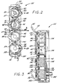
- the stud and eyelet assembly unit 25 comprises synchronously rotated eyelet and stud die wheels which assemble and deform the components in a web moving continuously through the nip formed between the two wheels.
- the stud die wheel and the eyelet die wheel have dies spaced about the circumference of the wheels.
- Each of the wheels is continuously supplied with either studs or eyelets.
- a suction means applied through the dies holds the studs and the eyelets on the dies until they reach the assembly point at the nip.
- the eyelet and the stud are assembled and deformed to form an integral structure through the web by the rotary motion of the die wheels.
- the eyelet die wheel 41 rotates in a counterclockwise direction, while the stud die wheel 42 rotates in a clockwise direction.
- the web 27 passes through the nip 43 formed between the two wheels 41, 42. So that the eyelets 31 and the studs 32 may be assembled and engaged in the web 27, the dies 45, 46 situated around the peripheries of the wheels 41, 42 synchronously rotate to the nip 43.
- the eyelets 31 and studs 32 as supported on these dies 45, 46 are assembled through the web 27 as the die wheels 41, 42 continously rotate and the web 27 progresses continously through the nip 43.
- the web 27 may pause momentarily to facilitate further operations, such as cutting the final assembly 28 from the web 27 at another processing unit 24, the web 27 moves continuously through the processing machine 20 as opposed, for example, to an indexed or stop-action movement.
- the post 49 of the eyelet 31 may pierce a hole in the web 27, enter a hole already punched through the web 27, or simply conform the web material to the shape of the post 49 and socket 50 mating, depending on the web material chosen.
- the post 49 may deform to take on the shape of the inside of the socket 50.
- the post 49 of the eyelet 31 deforms with the progressive rolling motion of the die wheels 41, 42 when it is assembled into the stud 32.
- the eyelet 31 and the stud 32 are both assembled and engaged at a single unit 25 of the web processing machine 20 without interfering with the continuous movement of the web 27 through the web processing machine 20.
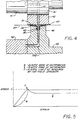
- the eyelet post 49 deforms plastically, as indicated by the zone designated b on the stress-strain diagram of FIG. 5.
- the stud 32 may be made of a suitable metal, such as, for example, stainless steel, nickel, tin, or plated brass.
- the eyelet 31 may also be made of a suitable metal, such as stainless steel, or it may be made of a suitable plastic, such as acrylonitrile-butadiene-styrene copolymer, Lexan®, or the like.
- the plastic may also be coated with a metal to render the eyelet electrically conductive.
- the post 49 of the plastic eyelet 31 plastically deforms to take on the shape of the socket 50 of the stainless steel stud 32.
- the invention is not intended to be limited only to the plastic zone b of deformation, but is intended to include both temporary and permanent deformation of the eyelet 31 and/or the stud 32. Therefore, the invention includes the assembly of a stud 32 and an eyelet 31 through a web 27 where the eyelet post 49 is plastically deformed to conform to the stud socket 50, and also where the socket 50 or the post 49 merely elastically deforms to cause an interference fit, as indicated by the zone a in FIG. 5.
- the eyelets 31 and studs 32 are transported through the assembly unit 25 in the same manner.
- the eyelets 31 and studs 32 may be supplied to the die wheels 41, 42 by transfer wheels 53, 54.
- Conventional feeding devices 35, 36 such as vibrating or rotating bowl feeders orient and feed eyelets 31 and studs 32 to magazine columns 55, 56, which supply components 31, 32 to the strippers 57, 58 of the adjacent transfer wheels 53, 54.
- the components 31, 32 are held on the respective wheels 41, 42, 53, 54 by a vacuum 60 transmitted from vacuum distributor plates 71, 72, 73, 74 to the dies 45, 46 and transfer wheel strippers 57, 58 by a series of distributor ports 81, 82, 83, 84, distributor channels 91, 92, 93, 94 , and internal wheel ports 101, 102, 103, 104.
- the wheels 41, 42, 53, 54 operate such that the eyelets transfer and die wheels 41, 53 rotate in a manner that is the mirror image of the rotation of the stud transfer and die wheels 42, 54.
- a single shaft 105 imparts rotation to one wheels 54 of the unit 25. This rotation is further transmitted to the remaining wheels 41, 42, 53 of the unit 25 through the meshing of gears 106 at the bases of the wheels 41, 42, 53, 54.
- the weight of the eyelets in the column 55 propels an eyelet 31 into a pickup position at a transfer points 110 at the base of the magazine column 55 adjacent to the eyelet transfer wheel 53.
- a support plate 111 extends from the eyelet magazine into the opening at the base of the magazine column 55.
- the eyelet 31 is further positioned by the side edges of the magazine sidewall 112 and the column of eyelets 113. So that the weight of the column of eyelets 113 may not push the eyelet 31 out of the pickup position at the transfer point 110, a gate 114 is provided, which is biased against the eyelet 31 by a spring 115.
- the post 49 of the eyelet 31 extends down from the support plate 111 when the eyelet 31 is in position at the transfer point 110, as shown in FIGS. 6A and 6B.
- the eyelet transfer wheel 53 In order to receive the eyelet 31 from the eyelet magazine 55, and to transport the eyelet 31 to the eyelet die wheel 41, the eyelet transfer wheel 53 is positioned adjacent to the eyelet magazine column 55.
- the eyelets 31 are held on the transfer wheel 53 by eyelet strippers 57 positioned about the periphery of the eyelet transfer wheel 53.
- the strippers are of a U-type shape, so that the center open area 116 may receive the post 49 of the eyelet 31. In this way, the stripper 57 engages the eyelet 31 from the magazine column 55 and properly orients the eyelet 31 for transfer to the eyelet die wheel 41.
- the inside surface 116 of the stripper 57 rotates into contact with the eyelet post 49 extending down from the support plate 111 at the transfer point 110 of the eyelet magazine 55. With further rotation of the transfer wheel 53, the inside surface 116 of the stripper 57 engages the eyelet post 49, forcing the post 49 and therefore the eyelet 31 from the stationary position on the eyelet support plate 111.
- the eyelet 31 moves with the stripper 57, it pushes against the gate 114 to pivot the gate 114 from its biased position.
- the upper face of the stripper 57 blocks the post 49 of the next eyelet 113 in the magazine column 55.
- the gate 114 pivots back to its bias position to support the next eyelet 113.
- the gate 114 brushes against the top surface 117 of the eyelet 31 and pushed the eyelet 31 against the stripper 57 as the gate 114 pivots back to its biased position.
- the eyelet transfer wheel 53 with the eyelet 31 in position on the stripper 57 continues to rotate in a clockwise direction.
- the weight of the eyelets 113 in the magazine column 55 propels the next eyelet 113 into the transfer position 100 at the base of the column 55. In this way, the next eyelet 113 is in in position for engagement with the next stripper 57 as the eyelet transfer wheel 53 continues to rotate.
- the stud 32 moves through the system in a manner similar to that described for the eyelet 31.
- the weight of the studs in the magazine column 56 above propels a stud 32 into the pickup position at a transfer point 120 at the base of the magazine column adjacent the stud transfer wheel 54.
- the wall 121 of the stud magazine 56 extends partially into the opening at the base of the column 56.
- the stud 32 is further positioned by the side 122 and back 123 wall of the magazine 56 at the opening.
- a gate 124 is biased against the stud 32 by a spring 125 and prevents the weight of the column of studs 126 from pushing the stud out of position, as shown in FIGS. 7A and 7B.
- Stud strippers 58 positioned about the periphery of the stud transfer wheel 54 receive the studs 32 from the adjacent stud magazine column 56 and transport the studs 32 to the adjacent die wheel 42. In order for the stud stripper 58 to engage the stud 32 as it passes the transfer point 139, the stripper 58 has a section 127 that protrudes from the transfer wheel as shown in FIGS. 7B and 7C.
- the protruding section 127 of the stripper 58 rotates into contact with the flange 128 of the stud 32 at the transfer point 120 of the stud magazine 56, as shown in FIG. 7B.
- the surface of the stripper 58 engages the stud flange 128, forcing the stud 32 from the stationary position at the transfer point 120 at the column base.
- the stud 32 pushes against the gate 124 to pivot the gate 124 from its biased position.
- the edge of the stripper 58 blocks the next stud 126 in the magazine column 56 to prevent its movement into the transfer point 120 while the gate 124 is not properly set to support the stud 126.
- the gate 124 brushes against the top of the socket 50 of the stud 32 and pushes the stud 32 against the stripper 58 as the gate 124 pivots backs to its biased position. In this way, the reset gate 124 supports and retains the next stud 126 propelled into the transfer position 120 at the base of the column 56 by the weight of the studs 126.
- An eyelet die wheel 41 is positioned adjacent the eyelet transfer whel 53, and a stud die wheel 42 is positioned adjacent the stud transfer wheel 54 to further transport the eyelets 31 and studs 32 through the assembly unit 25.
- the eyelets are transported by and moved between the eyelet transfer and die wheels 53, 41 in the same manner as the studs 32 are transported by and moved between the stud transfer and die wheels 54, 42.
- dies 45, 46 are spaced about the periphery of the die wheels 41, 42.
- dies 45, 46 support and align the components 31, 32 as the die wheels 41, 42 rotate the eyelet 31 and stud 32 into position at the web 27 for assembly at the nip 43.
- the eyelet die wheel 41 and the stud die wheel 42 rotate in opposite directions so that the web 27 may be advanced between the wheels 41, 42 at the same peripheral speed.
- the eyelet transfer wheel 53 and the eyelet die wheel 41 rotate in opposite directions to facilitate the transfer of eyelets 31 between the wheels 53, 41.
- the eyelet transfer wheel 53 and the eyelet die wheel 41 synchronously rotate in the clockwise and counterclockwise directions, respectively.
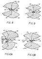
- an eyelet 31 supported on a stripper 57 of the eyelet transfer wheel 53 and a die 45 of the eyelet die wheel 41 simultaneously rotate to the transfer point 130, as shown in FIG. 8.
- the eyelet 31 subsequently transfers from the stripper 57 to the die 45.
- the eyelet transfer wheel 53 continuously rotates in the clockwise direction while releasing the eyelet 31, and the eyelet die wheel 41 continues to rotate in the counterclockwise direction with the eyelet 31 in position on the die 45.
- the eyelet 31 remains in position on the die 45 until it is assembled into the web 27 at the nip 43, and die wheel 41 continuously rotating during assembly and after releasing the eyelet 31, as shown in FIGS. 10A and 10B.
- the stud transfer wheel 54 and stud die wheel 42 synchronously rotate in the counterclockwise and clockwise directions, respectively.
- the stud 32 transfers from the stripper 58 to the die 46, as shown in FIG. 9.
- Both the wheels 54, 42 continue to rotate, the stud 32 remaining in position on the die 46 until it is assembled with the eyelet 31 at the web 27 at the nip 43, as shown in FIGS. 10A and 10B.
- the wheels 41, 42, 53, 54 are provided with a vacuum means, which may be drawn from any traditional source 60.
- the vacuum is applied to each wheel 41, 42, 53, 54 through inlet ports 81, 82, 83, 84 in stationary vacuum distributors 71, 72, 73, 74.
- the distributors 71, 72, 73, 74 are spring-loaded against each wheel 41, 42, 53, 54 by spring 141 and bracket 142 mechanisms.
- the distributors 71, 72, 73, 74 may transmit the vacuum to the transfer and die wheels 41, 42, 53, 54, the inlet ports 81, 82, 83, 84 communicate with arcuate channels 91, 92, 93, 94 in the surfaces of the distributors 71, 72, 73, 74 at the interface of the distributors 71, 72, 73, 74 with the wheels 41, 42, 53, 54.
- the wheels 41, 42, 53, 54 have internal ports 101, 102, 103, 104 that extend from the distributor 71, 72, 73, 74/wheel 41, 42, 53, 54 interface of the surface of the stripper 57, 58 or die 45, 46.
- a transfer wheel port 103, 104 first communicates with the arcuate channel 93, 94 when the corresponding stripper 57, 58 receives an eyelet 31 or stud 32 from the transfer point 110, 120 at the eyelet magazine 55 or the stud magazine 56, thus holding the component 31, 32 in position on the stripper 57, 58.
- the transfer wheel port 103, 104 continues to communicate with the arcuate channel 93, 94, as the transfer wheel 53, 54 rotates, so that the vacuum is continuously exerted on the eyelet 31 or stud 32.
- the stripper 57, 58 of the transfer wheels 53, 54 and the dies 45, 46 of the die wheels 41, 42 rotate to the transfer points 130, 140 between the wheels 53 and 41, 54 and 42 as shown in FIGS. 8 and 9, synchronously.
- the internal ports 101, 102 of the die wheels 41, 42 rotate into communication with the arcuate channels 91, 92 of the stationary die wheel distributors 71, 72; in this way, the vacuum source 60 exerts a retaining vacuum on the eyelet 31 or the stud 32 when the corresponding die 45, 46 reaches the transfer point 130, 140 at the eyelet transfer wheel 53 or the stud transfer wheel 54.
- the eyelet 31 is transferred from the eyelet transfer wheel 53 to the eyelet die wheel 41 at the transfer point 130
- the stud 32 is transferred from the stud transfer wheel 54 to the stud die wheel 42 at the transfer point 140.
- the internal ports 101, 102 of the die wheels 41, 42 continues to communicate with the arcuate channels 91, 92 of the vacuum distributors 71, 72 to exert a retaining vacuum on the components 31, 32.
- the dies 45, 46 supporting the eyelet 31 and stud 32 reach the nip 43 formed between the die wheels 41, 42, the corresponding internal ports 101, 102 pass beyond contact with the arcuate channels 91, 92 so that the vacuum is no longer exerted on the components 31, 32.
- the web 27 is continuously advanced through the nip 43 formed between the eyelet die wheel 41 and the stud die wheel 42.
- the eyelet 31 in position on the die 45 of the eyelet die wheel 41, rotating in a counterclockwise direction, and the stud 32 on the die 46 of the stud die wheel 42, rotating in a clockwise direction move toward the nip 43 in synchronous rotation.
- the web 27 advances through the nip 43 formed between the die wheels 41, 42 at a velocity equal to the tangential velocity of the synchronously rotating die wheels 41, 42. In this way, the stud 32 and the eyelet 31 may be efficiently and accurately assembled in the web 27 moving through the nip 43.
- the post 49 of the eyelet 31 enters the socket 50 of the synchronously moving stud 32 in assembly at the web 27. So as to create a unitary structure in the web 27 at the nip 43, the post 49 of the eyelet 31 deforms as it rolls into the socket 50 of the stud 32. In this way, the complete assembly of the eyelet 31 and the stud 32 in the web 27 occurs at a single unit 25 without disrupting the continuous movement of the web 27 through the processing operations of a web processing machine 20.
- a single input shaft 105 imparts rotation to one wheel 54 as shown in FIG. 3.
- a gear 106 is provided at the base of each wheel, which meshes with the gears 106 at the bases of the adjacent wheels. In this way, the single input 105 to one such wheel 54 is transmitted to each of the wheels 42, 41, 53 to rotate the wheels 54, 42, 41, 53 synchronously.
- strippers on eyelet and stud transfer wheels strip eyelets and studs from pickup points at the bases of the eyelet and stud magazines, respectively.
- the eyelets and studs transfer from the strippers of the transfer wheels to the dies of the eyelet and stud die wheels.
- the eyelets and studs are retained on the strippers and dies by a vacuum supplied through internal channels and ports.
- the die wheels supporting the eyelets and studs on dies about its periphery, rotate to assemble the eyelets and studs in a web moving continuously through the nip formed between the die wheels.
- the rotary device provides a versatile, simplified assembly method, which may be efficiently adapted to a highly automated processing unit.
Landscapes
- Engineering & Computer Science (AREA)
- Mechanical Engineering (AREA)
- Textile Engineering (AREA)
- Tyre Moulding (AREA)
- Blow-Moulding Or Thermoforming Of Plastics Or The Like (AREA)
- Lining Or Joining Of Plastics Or The Like (AREA)
- Automatic Assembly (AREA)
Applications Claiming Priority (2)
| Application Number | Priority Date | Filing Date | Title |
|---|---|---|---|
| US07/149,109 US4817261A (en) | 1988-01-26 | 1988-01-26 | Rotary snap machine |
| US149109 | 1988-01-26 |
Publications (2)
| Publication Number | Publication Date |
|---|---|
| EP0326358A2 true EP0326358A2 (de) | 1989-08-02 |
| EP0326358A3 EP0326358A3 (de) | 1989-10-25 |
Family
ID=22528844
Family Applications (1)
| Application Number | Title | Priority Date | Filing Date |
|---|---|---|---|
| EP89300708A Withdrawn EP0326358A3 (de) | 1988-01-26 | 1989-01-25 | Rotationsmaschine zum Anbringen von Druckknopfteilen |
Country Status (4)
| Country | Link |
|---|---|
| US (1) | US4817261A (de) |
| EP (1) | EP0326358A3 (de) |
| JP (1) | JPH0274602A (de) |
| KR (1) | KR890011674A (de) |
Cited By (2)
| Publication number | Priority date | Publication date | Assignee | Title |
|---|---|---|---|---|
| FR2769258A1 (fr) * | 1997-10-07 | 1999-04-09 | Seb Sa | Procede d'assemblage rotatif d'une piece plastique rigide sur une structure souple |
| WO1999054116A1 (en) * | 1998-04-23 | 1999-10-28 | Minnesota Mining And Manufacturing Company | Method and apparatus for assembling an optical recording medium |
Family Cites Families (17)
| Publication number | Priority date | Publication date | Assignee | Title |
|---|---|---|---|---|
| US1193113A (en) * | 1916-08-01 | brown | ||
| US283923A (en) * | 1883-08-28 | Machine foe shaping and riveting spiral pipe | ||
| US637779A (en) * | 1899-03-18 | 1899-11-28 | Anton Groeschel | Machine for providing leather soles with plugs. |
| US686738A (en) * | 1900-03-02 | 1901-11-19 | Christian S E Spoerl | Machine for making tufted fabrics. |
| US677711A (en) * | 1901-02-19 | 1901-07-02 | John A Wilbur | Rivet-feeding apparatus. |
| US1518065A (en) * | 1923-03-15 | 1924-12-02 | Hall Bicknell | Hole-punching and eyelet-setting machine |
| US1918961A (en) * | 1931-01-22 | 1933-07-18 | Foster John Fagg | Machine for applying reenforcing eyelets to paper |
| US3013693A (en) * | 1950-08-23 | 1961-12-19 | Nat Biscuit Co | Sandwich machines |
| US3323274A (en) * | 1964-01-27 | 1967-06-06 | Beloit Corp | Vacuum plastic bottle forming machine and method |
| DK108962C (da) * | 1965-07-16 | 1968-02-26 | Carmo Handels Og Industriselsk | Apparat til ordnet fremføring af ensartede genstande. |
| US3367550A (en) * | 1965-11-05 | 1968-02-06 | American Leather Specialties C | Automatic stud setting apparatus |
| US3668771A (en) * | 1970-06-12 | 1972-06-13 | Kimberly Clark Co | Method and apparatus for affixing fasteners to a moving web |
| CH512893A (fr) * | 1970-09-14 | 1971-09-30 | Vautier Freres Succursale De B | Machine à insérer les filtres dans les embouts pour articles à fumer |
| JPS5143422B2 (de) * | 1972-04-18 | 1976-11-22 | ||
| CA1079695A (en) * | 1977-11-30 | 1980-06-17 | Conrad Leblanc | Method and apparatus for setting fastener elements into a blank |
| US4315588A (en) * | 1980-01-21 | 1982-02-16 | Faltin Hans G | High speed on-line stitcher for signatures and webs |
| US4547645A (en) * | 1983-02-01 | 1985-10-15 | American Can Company | Material handling method and apparatus therefor |
-
1988
- 1988-01-26 US US07/149,109 patent/US4817261A/en not_active Expired - Lifetime
-
1989
- 1989-01-25 JP JP1016061A patent/JPH0274602A/ja active Pending
- 1989-01-25 EP EP89300708A patent/EP0326358A3/de not_active Withdrawn
- 1989-01-26 KR KR1019890000783A patent/KR890011674A/ko not_active Withdrawn
Cited By (4)
| Publication number | Priority date | Publication date | Assignee | Title |
|---|---|---|---|---|
| FR2769258A1 (fr) * | 1997-10-07 | 1999-04-09 | Seb Sa | Procede d'assemblage rotatif d'une piece plastique rigide sur une structure souple |
| EP0908293A1 (de) * | 1997-10-07 | 1999-04-14 | Seb S.A. | Verfahren zum Verbinden eines festen Kunststoffteiles mit einem flexibelen Film auf eine Walze |
| WO1999054116A1 (en) * | 1998-04-23 | 1999-10-28 | Minnesota Mining And Manufacturing Company | Method and apparatus for assembling an optical recording medium |
| US6066218A (en) * | 1998-04-23 | 2000-05-23 | 3M Innovative Properties Company | Method and apparatus for assembling an optical recording medium |
Also Published As
| Publication number | Publication date |
|---|---|
| EP0326358A3 (de) | 1989-10-25 |
| KR890011674A (ko) | 1989-08-21 |
| US4817261A (en) | 1989-04-04 |
| JPH0274602A (ja) | 1990-03-14 |
Similar Documents
| Publication | Publication Date | Title |
|---|---|---|
| US4784059A (en) | Credit card embossing system | |
| US3378907A (en) | Workpiece transfer mechanism for use with assembling machines and the like | |
| EP0752309A2 (de) | Prägevorrichtung | |
| US5768931A (en) | Article processing machine | |
| US5577313A (en) | Method and apparatus for joining deformable sheet stock | |
| EP0589203B1 (de) | Dosenformvorrichtung | |
| US4954207A (en) | Apparatus for automatically taping electronic components | |
| EP0326358A2 (de) | Rotationsmaschine zum Anbringen von Druckknopfteilen | |
| US3063347A (en) | Cup making machine | |
| US3862486A (en) | Method and machine for applying pour spouts to containers | |
| US3495315A (en) | Apparatus for loading a tape with fasteners | |
| JPH0880013A (ja) | 突起部を有した鉄心板からなる鉄心およびその製造方法とその鉄心板のプレス抜き型とその鉄心板の製造装置およびその鉄心板の製造方法 | |
| CN220964600U (zh) | 一种电机磁环点胶组装装置 | |
| US4459840A (en) | Rolling wobble press | |
| CN210010352U (zh) | 一种多工位母线加工机 | |
| JPS63123606A (ja) | 缶のねじ切り装置 | |
| US3661251A (en) | Strip of fasteners in a predetermined sequence | |
| KR20050026430A (ko) | 회전 컬링 시스템 및 컬링 방법 | |
| US3863534A (en) | Press for punching memory cores | |
| US2217714A (en) | Self-locking nut and manufacture thereof | |
| JP2001155695A (ja) | 電池外装缶の端部カーリング加工装置 | |
| US2893731A (en) | Sheet side gauging apparatus | |
| US6405430B1 (en) | Workpiece moving methods | |
| JPH0792991B2 (ja) | ディスクカートリッジ製造方法及び製造装置 | |
| CN210650951U (zh) | 一种引导带定位传送组件及裁切系统 |
Legal Events
| Date | Code | Title | Description |
|---|---|---|---|
| PUAI | Public reference made under article 153(3) epc to a published international application that has entered the european phase |
Free format text: ORIGINAL CODE: 0009012 |
|
| AK | Designated contracting states |
Kind code of ref document: A2 Designated state(s): CH DE FR GB IT LI NL |
|
| PUAL | Search report despatched |
Free format text: ORIGINAL CODE: 0009013 |
|
| ITCL | It: translation for ep claims filed |
Representative=s name: MODIANO & ASSOCIATI S.R.L. |
|
| RAP3 | Party data changed (applicant data changed or rights of an application transferred) |
Owner name: FERRIS MFG., CORP. |
|
| AK | Designated contracting states |
Kind code of ref document: A3 Designated state(s): CH DE FR GB IT LI NL |
|
| STAA | Information on the status of an ep patent application or granted ep patent |
Free format text: STATUS: THE APPLICATION IS DEEMED TO BE WITHDRAWN |
|
| 18D | Application deemed to be withdrawn |
Effective date: 19900426 |