EP0326497B1 - Caméra vidéo électronique pour usage dentaire et instrument dentaire - Google Patents
Caméra vidéo électronique pour usage dentaire et instrument dentaire Download PDFInfo
- Publication number
- EP0326497B1 EP0326497B1 EP89400241A EP89400241A EP0326497B1 EP 0326497 B1 EP0326497 B1 EP 0326497B1 EP 89400241 A EP89400241 A EP 89400241A EP 89400241 A EP89400241 A EP 89400241A EP 0326497 B1 EP0326497 B1 EP 0326497B1
- Authority
- EP
- European Patent Office
- Prior art keywords
- camera
- dental
- image
- dental camera
- camera head
- Prior art date
- Legal status (The legal status is an assumption and is not a legal conclusion. Google has not performed a legal analysis and makes no representation as to the accuracy of the status listed.)
- Expired - Lifetime
Links
- 239000013307 optical fiber Substances 0.000 claims description 8
- 230000003287 optical effect Effects 0.000 claims description 3
- 239000000835 fiber Substances 0.000 description 19
- 238000005286 illumination Methods 0.000 description 13
- 238000003384 imaging method Methods 0.000 description 8
- 238000010586 diagram Methods 0.000 description 5
- 239000012530 fluid Substances 0.000 description 5
- 239000003086 colorant Substances 0.000 description 4
- 239000004020 conductor Substances 0.000 description 3
- 238000000034 method Methods 0.000 description 3
- 230000000712 assembly Effects 0.000 description 2
- 238000000429 assembly Methods 0.000 description 2
- 230000005540 biological transmission Effects 0.000 description 2
- 239000006185 dispersion Substances 0.000 description 2
- 239000000758 substrate Substances 0.000 description 2
- 238000001356 surgical procedure Methods 0.000 description 2
- 241000251468 Actinopterygii Species 0.000 description 1
- 230000000903 blocking effect Effects 0.000 description 1
- 230000017531 blood circulation Effects 0.000 description 1
- 230000007547 defect Effects 0.000 description 1
- 210000004262 dental pulp cavity Anatomy 0.000 description 1
- 229910052736 halogen Inorganic materials 0.000 description 1
- 150000002367 halogens Chemical class 0.000 description 1
- 238000003780 insertion Methods 0.000 description 1
- 230000037431 insertion Effects 0.000 description 1
- 239000007788 liquid Substances 0.000 description 1
- 230000000873 masking effect Effects 0.000 description 1
- 238000012544 monitoring process Methods 0.000 description 1
- XLYOFNOQVPJJNP-UHFFFAOYSA-N water Substances O XLYOFNOQVPJJNP-UHFFFAOYSA-N 0.000 description 1
- 229910052724 xenon Inorganic materials 0.000 description 1
- FHNFHKCVQCLJFQ-UHFFFAOYSA-N xenon atom Chemical compound [Xe] FHNFHKCVQCLJFQ-UHFFFAOYSA-N 0.000 description 1
Images




Classifications
-
- A—HUMAN NECESSITIES
- A61—MEDICAL OR VETERINARY SCIENCE; HYGIENE
- A61B—DIAGNOSIS; SURGERY; IDENTIFICATION
- A61B1/00—Instruments for performing medical examinations of the interior of cavities or tubes of the body by visual or photographical inspection, e.g. endoscopes; Illuminating arrangements therefor
- A61B1/24—Instruments for performing medical examinations of the interior of cavities or tubes of the body by visual or photographical inspection, e.g. endoscopes; Illuminating arrangements therefor for the mouth, i.e. stomatoscopes, e.g. with tongue depressors; Instruments for opening or keeping open the mouth
-
- A—HUMAN NECESSITIES
- A61—MEDICAL OR VETERINARY SCIENCE; HYGIENE
- A61B—DIAGNOSIS; SURGERY; IDENTIFICATION
- A61B1/00—Instruments for performing medical examinations of the interior of cavities or tubes of the body by visual or photographical inspection, e.g. endoscopes; Illuminating arrangements therefor
- A61B1/00064—Constructional details of the endoscope body
- A61B1/00071—Insertion part of the endoscope body
- A61B1/0008—Insertion part of the endoscope body characterised by distal tip features
- A61B1/00091—Nozzles
-
- A—HUMAN NECESSITIES
- A61—MEDICAL OR VETERINARY SCIENCE; HYGIENE
- A61B—DIAGNOSIS; SURGERY; IDENTIFICATION
- A61B1/00—Instruments for performing medical examinations of the interior of cavities or tubes of the body by visual or photographical inspection, e.g. endoscopes; Illuminating arrangements therefor
- A61B1/00064—Constructional details of the endoscope body
- A61B1/00071—Insertion part of the endoscope body
- A61B1/0008—Insertion part of the endoscope body characterised by distal tip features
- A61B1/00096—Optical elements
-
- A—HUMAN NECESSITIES
- A61—MEDICAL OR VETERINARY SCIENCE; HYGIENE
- A61B—DIAGNOSIS; SURGERY; IDENTIFICATION
- A61B1/00—Instruments for performing medical examinations of the interior of cavities or tubes of the body by visual or photographical inspection, e.g. endoscopes; Illuminating arrangements therefor
- A61B1/00064—Constructional details of the endoscope body
- A61B1/00071—Insertion part of the endoscope body
- A61B1/0008—Insertion part of the endoscope body characterised by distal tip features
- A61B1/00101—Insertion part of the endoscope body characterised by distal tip features the distal tip features being detachable
-
- A—HUMAN NECESSITIES
- A61—MEDICAL OR VETERINARY SCIENCE; HYGIENE
- A61B—DIAGNOSIS; SURGERY; IDENTIFICATION
- A61B1/00—Instruments for performing medical examinations of the interior of cavities or tubes of the body by visual or photographical inspection, e.g. endoscopes; Illuminating arrangements therefor
- A61B1/04—Instruments for performing medical examinations of the interior of cavities or tubes of the body by visual or photographical inspection, e.g. endoscopes; Illuminating arrangements therefor combined with photographic or television appliances
- A61B1/05—Instruments for performing medical examinations of the interior of cavities or tubes of the body by visual or photographical inspection, e.g. endoscopes; Illuminating arrangements therefor combined with photographic or television appliances characterised by the image sensor, e.g. camera, being in the distal end portion
-
- A—HUMAN NECESSITIES
- A61—MEDICAL OR VETERINARY SCIENCE; HYGIENE
- A61B—DIAGNOSIS; SURGERY; IDENTIFICATION
- A61B1/00—Instruments for performing medical examinations of the interior of cavities or tubes of the body by visual or photographical inspection, e.g. endoscopes; Illuminating arrangements therefor
- A61B1/06—Instruments for performing medical examinations of the interior of cavities or tubes of the body by visual or photographical inspection, e.g. endoscopes; Illuminating arrangements therefor with illuminating arrangements
- A61B1/07—Instruments for performing medical examinations of the interior of cavities or tubes of the body by visual or photographical inspection, e.g. endoscopes; Illuminating arrangements therefor with illuminating arrangements using light-conductive means, e.g. optical fibres
-
- A—HUMAN NECESSITIES
- A61—MEDICAL OR VETERINARY SCIENCE; HYGIENE
- A61B—DIAGNOSIS; SURGERY; IDENTIFICATION
- A61B1/00—Instruments for performing medical examinations of the interior of cavities or tubes of the body by visual or photographical inspection, e.g. endoscopes; Illuminating arrangements therefor
- A61B1/12—Instruments for performing medical examinations of the interior of cavities or tubes of the body by visual or photographical inspection, e.g. endoscopes; Illuminating arrangements therefor with cooling or rinsing arrangements
- A61B1/127—Instruments for performing medical examinations of the interior of cavities or tubes of the body by visual or photographical inspection, e.g. endoscopes; Illuminating arrangements therefor with cooling or rinsing arrangements with means for preventing fogging
-
- A—HUMAN NECESSITIES
- A61—MEDICAL OR VETERINARY SCIENCE; HYGIENE
- A61B—DIAGNOSIS; SURGERY; IDENTIFICATION
- A61B1/00—Instruments for performing medical examinations of the interior of cavities or tubes of the body by visual or photographical inspection, e.g. endoscopes; Illuminating arrangements therefor
- A61B1/24—Instruments for performing medical examinations of the interior of cavities or tubes of the body by visual or photographical inspection, e.g. endoscopes; Illuminating arrangements therefor for the mouth, i.e. stomatoscopes, e.g. with tongue depressors; Instruments for opening or keeping open the mouth
- A61B1/247—Instruments for performing medical examinations of the interior of cavities or tubes of the body by visual or photographical inspection, e.g. endoscopes; Illuminating arrangements therefor for the mouth, i.e. stomatoscopes, e.g. with tongue depressors; Instruments for opening or keeping open the mouth with means for viewing areas outside the direct line of sight, e.g. dentists' mirrors
-
- A—HUMAN NECESSITIES
- A61—MEDICAL OR VETERINARY SCIENCE; HYGIENE
- A61B—DIAGNOSIS; SURGERY; IDENTIFICATION
- A61B5/00—Measuring for diagnostic purposes; Identification of persons
- A61B5/0059—Measuring for diagnostic purposes; Identification of persons using light, e.g. diagnosis by transillumination, diascopy, fluorescence
- A61B5/0082—Measuring for diagnostic purposes; Identification of persons using light, e.g. diagnosis by transillumination, diascopy, fluorescence adapted for particular medical purposes
- A61B5/0088—Measuring for diagnostic purposes; Identification of persons using light, e.g. diagnosis by transillumination, diascopy, fluorescence adapted for particular medical purposes for oral or dental tissue
-
- A—HUMAN NECESSITIES
- A61—MEDICAL OR VETERINARY SCIENCE; HYGIENE
- A61C—DENTISTRY; APPARATUS OR METHODS FOR ORAL OR DENTAL HYGIENE
- A61C1/00—Dental machines for boring or cutting ; General features of dental machines or apparatus, e.g. hand-piece design
- A61C1/08—Machine parts specially adapted for dentistry
-
- H—ELECTRICITY
- H04—ELECTRIC COMMUNICATION TECHNIQUE
- H04N—PICTORIAL COMMUNICATION, e.g. TELEVISION
- H04N23/00—Cameras or camera modules comprising electronic image sensors; Control thereof
- H04N23/56—Cameras or camera modules comprising electronic image sensors; Control thereof provided with illuminating means
-
- A—HUMAN NECESSITIES
- A61—MEDICAL OR VETERINARY SCIENCE; HYGIENE
- A61B—DIAGNOSIS; SURGERY; IDENTIFICATION
- A61B2562/00—Details of sensors; Constructional details of sensor housings or probes; Accessories for sensors
- A61B2562/02—Details of sensors specially adapted for in-vivo measurements
- A61B2562/0233—Special features of optical sensors or probes classified in A61B5/00
- A61B2562/0238—Optical sensor arrangements for performing transmission measurements on body tissue
-
- H—ELECTRICITY
- H04—ELECTRIC COMMUNICATION TECHNIQUE
- H04N—PICTORIAL COMMUNICATION, e.g. TELEVISION
- H04N23/00—Cameras or camera modules comprising electronic image sensors; Control thereof
- H04N23/50—Constructional details
- H04N23/555—Constructional details for picking-up images in sites, inaccessible due to their dimensions or hazardous conditions, e.g. endoscopes or borescopes
Definitions
- This invention is an electronic video dental camera having a handle and head for use in placement in a dental patient's mouth, and allowing areas within the mouth be displayed via a video signal.
- the invention relates to improvements to the electronic video dental camera defined in the intermediate document EP-A-0,280,823.
- the dental camera adapted to be attached to the handle of a dental treatment tool.
- the dental camera comprises a light generator, a light conductor coupled to the light generator, an image conductor, an image receiver coupled to the image conductor so as to give an image of the treated part, a tooth for example.
- DE-A-2208902 teaches a dental camera for use in displaying an image form inside the mouth onto a monitor comprising an electronic video endoscope, the endoscope comprising :
- DE-A-3716401 discloses an adaptator for the head of an endoscope, said adaptator comprising means to adapt the direction of observation of the endoscope as well as means for adapting the viewing angle.
- US-A-4468197 discloses an apparatus for detecting cavities, particularly for checking teeth in a patient's mouth by a dentist.
- a high intensity light from an incandescent lamp is transmitted through an optical fiber bundle and is projected onto a tooth.
- Light passing around or through said tooth is detected by a second optical fiber bundle and is transmitted to a viewer where it is projected through a lense system onto an opaque screen where an image of the tooth can be viewed and any defects therein can be detected.
- an electronic video dental camera which overcomes the disadvantages of both prior art dental mirrors, endoscopes, video endoscopes and electronic video dental cameras.
- the handle is uniquely designed to include electronics, such as video amplifiers and imaging device driver circuitry, thereby eliminating the need to include this circuitry in the camera head itself.
- a preferred embodiment includes a dental camera head which allows a number of attachments to be used, such as a telephoto lens, wide angle lens, relay lens, and transillumination devices.
- the dental camera is attached to another dental instrument, such a dentist's drill, thereby allowing video monitoring of the task being performed by the dentist.
- the dental camera is formed as an integral part of the dental instrument, such as dental drill.
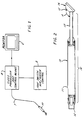
- Fig. 1 shows the use of a dental camera 10 constructed in accordance with the teachings of EP-A-0,280,823.
- Video processor and control means 8 serves to provide power, light and, if desired, fluid and other appropriate signals via cable 7 to dental camera 10.
- Video processor and control means 8 provides a video signal to video monitor 6 in order that users may view a location within a patient's mouth by way of dental camera 10.
- foot switch 9 is used to provide a signal to video processor and control means 8 indicating when air and/or fluids are to be sent by video processor and control means 8 to dental camera 10.
- FIG. 2 shows a cross section of one embodiment of a video dental camera constructed in accordance with the teachings of EP-A-0,280,823.
- Video dental camera 10 includes body 16 having handle 11 suitable for being held by an operator, and, if desired having forward extension 13. At one end of handle 11 is located connector 12 for connection, via a cable assembly (not shown) to video processor and control unit 8 (Fig. 1).
- Sf desired, forward extension 13 and handle 11 have generally circular cross section, although other suitable shapes, such as octagonol, and polygonal can be used.
- handle 11 should be easily and comfortably gripped by the user, and forward extension 13 should be of a general size and cross section which is convenient for insertion into the patient's mouth and, of course, comfortable for the patient.
- camera head 14 Located at the distal end of forward extension 13, and mounted on forward extension 13 at an angle A to forward extension 13, is camera head 14. Face 15 of camera head 14 includes means for receiving an image within a patient's mouth to be displayed on a video monitor.
- such means for receiving the image is fiber optic tubes or one or more rod lens assemblies or a combination thereof with or without additional lenses, which transmit the image to an image sensor (not shown) either within forward extension 13, body 16 or, in another embodiment of EP-A-0,280,823 , the image is transmitted by one or more rod lens assemblies or fiber optic cable, or a combination thereof with or without additional lenses, through connector 12 to an image sensor located in external video equipment (not shown).
- the image sensor is located directly in camera head 14 and receives the image from the patient's mouth via a lens, without the need for fiber optics.
- Fig. 3 shows a cross sectional phantom view of camera head 14.
- fiber optic light guides 30a and 30b are used to receive light from a light source (not shown) which may comprise, for example a halogen lamp or a Xenon arc lamp located at the proximal end of light guides 30a and 30b, and conduct this light through fiber optic curvatures 31a and 31b to illumination lenses 32a and 32b respectively.
- image lens 33 and image sensor 35 which is mounted on hybrid assembly substrate 36 located within cavity 37. As shown in Fig.
- the center of the ends of fiber optic light pipes 30a and 30b are offset from the center of illumination lenses 32a and 32b, respectively, in a direction toward image lens 33. This causes the light being emitted from fiber optic light pipes 30a and 30b to be directed toward the image being viewed.
- illumination lenses 32a and 32b are dispersion lenses which include a "frosting" to disperse the light.
- Image sensor 35 is connected to video control cable 34 which communicates power and control signals to image sensor 35 and communicates video signals to the video processor and control means 8 of Fig. 1.
- Fig. 4 shows a cross sectional phantom view of the structure shown in Fig. 3, with elements numbered in a similar fashion.
- fiber optic light guide 30, fiber optic curvature 31 and illumination lens 32 are fiber optic light guide 30, fiber optic curvature 31 and illumination lens 32.
- illumination lens 32 is a dispersion lens which serves to properly distribute the light over a wider angle and area upon exit from fiber optic light guide 30, to correspond to the field of view of image lens 33.
- Fig. 4 also shows image lens 33 located within camera head 14 between camera head face 15 and image sensor 35. In the embodiment shown in Fig. 4. image lens 33 is affixed directly to image sensor 35.
- image lens 33 is affixed to the body of camera head 14, and image sensor 35 is also affixed, via substrate 36, to the body of camera head 14, thereby maintaining image lens 33 and image device 35 in fixed relationship.
- fiber optic curvature 31 is not used, but is replaced by a prism or mirror assembly which serves to reflect light from fiber optic light guide 30 to face 15 of camera head 14. If desired, a suitable lens can be placed on the fiber optic side of the prism or mirror, or on the face 15 side of the prism or mirror, or in both locations if desired.
- an infrared filter is place between the light source (not shown) and fiber optic light guide 30.
- This infrared filter serves to prevent damage to fiber optic light guide 30 by masking out damaging infrared rays from the light source.
- color filters are used as desired.
- color filters can be placed anywhere between the light source and illumination lens 32 in order to selectively apply desired colors of illumination to the image being viewed.
- one or more color filters can be placed between image lens 33 and image sensor 35, again in order to selectively remove desired colors of the image being presented to image sensor 35.
- an infrared blocking filter is placed in the image path between the image being viewed and image sensor 35 in order to prevent infrared energy from being applied to image sensor 35. This is particularly useful, for example, when a dentist is using a laser to perform certain dental procedures during which time a relatively larger amount of infrared energy is present. If not blocked out, this infrared energy would be detected by image sensor 35, resulting in a "washed out" video signal.
- forward extension 13 includes fluid jet 39 (Fig. 4) which serves to allow fluid to be introduce across face 15 of camera head 14.
- a constant or pulsed flow of gas such as air
- a liquid such as water can be introduced as well in order to clean image lens 33.
- Fluid jet 39 can also be placed in any convenient location.
- Fig. 5 is a block diagram of the electronics portion of a dental camera which includes image device 60 such as a charge coupled device (CCD), image device driver buffer 61 which serves to control image device 60, video amplifier circuitry 62, and video processor 8 for controlling driver buffer 61 and processing the video information which is then presented to display 6.
- image device 60 such as a charge coupled device (CCD)
- image device driver buffer 61 which serves to control image device 60
- video amplifier circuitry 62 for controlling driver buffer 61 and processing the video information which is then presented to display 6.
- driver buffer 61 and video amplifier 62 are located very close to image device 60 in order to maintain the necessary drive pulse waveforms and timing relationships, and insure the optimum frequency response of the video image.
- these circuits are fabricated on the same integrated circuit as imaging device 60.
- driver buffer 61 and video amplifier 62 are formed as individual components in a hybrid or printed circuit board assembly with imaging device 60.
- the heat generated by driver buffer 61 and video amplifier 62 can, in certain instances, impair the operation of the imaging device 60, for example by raising the dark current.
- driver buffer 61 and video amplifier 62 are located as either individual circuits, a single integrated circuit, or a hybrid assembly, located in the handle 11 (Fig. 1).
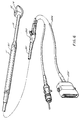
- Fig. 6 is a drawing of one embodiment of a dental camera constructed in accordance with the teachings of this invention.
- circuitry 101 is included within handle 11.
- Circuitry 101 can include one or both driver buffer 61 and video amplifier 62 (Fig. 5), and can be formed either as an integrated circuit, hybrid device, or components located on a printed circuit board or the like.
- Fig. 7 is a diagram of a dental camera constructed in accordance with a preferred embodiment of this invention which includes provisions in head 14 for mounting an external device.
- a dental camera is provided which allows for such external devices to be removed and interchanged, thereby allowing a single dental camera to serve a wide of number of uses.
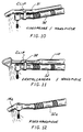
- a number of possible external devices are provided, including a wide angle lens as shown in Fig. 7, or a telephoto lens as shown in Fig. 7a, or a rod lens or one or more fiber optic cables serving as a "relay lens” as shown in Fig. 7b.
- a telephoto lens of Fig. 7a is very convenient for viewing very small areas, for example for use in viewing the capillaries within the gums, thereby allowing the dentist or oral surgeon to determine the relative health of the gums by determining the condition of blood circulation within the gums.
- Such a telephoto lens is also useful for obtaining a frontal view of the entire mouth, by holding the telephoto lens at an appropriate distance from the patient's face.
- a relay lens as in Figs. 7b and 7c is highly suitable for viewing the small spaces between the teeth more readily than can be viewed using the dental camera itself.
- Each of these examples in Figs. 7, 7a, and 7b include provisions for providing light to the area to be imaged. These take the form of additional lenses or windows 102 which optimize the area and uniformity of illumination to correspond to the angle of view of the lens being used.
- a relay lens as shown in Fig. 7c is provided, in which, for example, an optical fiber is used to both transmit light to the area to be imaged, and transmit the image to the dental camera imaging device contained within dental camera head 14.
- Filter attachments and lens/filter combinations can also be used.
- infrared filters can be used to block infrared energy emitted by a laser during surgery, thereby allowing proper viewing of the surgery in process.
- color filters can be placed in the path of the light being emitted by the light source in order to selectively apply desired colors of illumination to the image being viewed.
- filters can be placed in the path of the light being received by the image device in order to selectively remove desired colors of the image being present to the image sensor.
- Figs. 8, 8a, and 8b show alternative embodiments of the wide angle, telephoto, and relay lenses, respectively, which are capable of being clipped on to dental camera head 14 which includes slots 105 for reception of attachment bracket 106. Filters can also be used as described above with regard to Fig. 7.
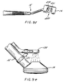
- Figs. 9a through 9d depict various embodiments of a dental camera constructed in accordance with the teachings of this invention suitable for transillumination of an area to be examined.
- illumination means 30 such as an optical fiber, receives light from a light source within camera head 14 (or via means which carries light to camera head 14), and provides this light via, for example, optical fibers or a rod lens, to the opposite side of the area being examined, for example a tooth, thereby allowing the tooth to be transilluminated and the image provided to the dental camera head being that of the transilluminated tooth.
- this transillumination technique will allow the exterior of the tooth to be illuminated, and the interior of the tooth to be viewed, for example to view a cavity within the tooth, or the root canal.
- illumination means 30 are malleable in order to allow their position with respect to camera head 14 to be altered, as desired.
- means 38 such as one or more optical fibers, or a rod lens, for transmission to the imaging device within the dental camera.
- means 38 is malleable to allow its position relative to camera head 14 to be altered, as desired.
- a separate transillumination light source 130 is used, which is attached to camera body 16 by attachment means 131
- attachment means 131 can allow the position of transillumination light source 130 to be changed relative to camera head 14.
- camera head 14 either does not include light sources, or the light sources contained within camera head 14 are turned off during the use of transillumination light source 130.
- Fig. 9f depicts an alternative embodiment of a transillumination device constructed in accordance with the teachings of this invention.
- camera head 14 includes a central cavity 220 which is placed in order to house the object to be transilluminated.
- optical ports 230 and 231 are included on the interior walls of transillumination head 14 . either one of which may be the source of transillumination light, with the opposite optical port serving as the port for receiving the transilluminated image.
- a rod lens or one or more optical fibers 91 are used for attaching the dental camera directly to a dentist's drill 92, thereby allowing the operation being performed by the dentist using his drill to be viewed on a video monitor.
- a dental camera 10 is mounted to a dental drill 92, for example, by means of one or more clips or ties 98.
- the dental camera and dental drill are combined in a single instrument including camera head 14a attached to the end of dental drill/camera 92a.
- camera head 14a includes an imaging device.
- camera head 14a includes means for receiving image, such as a fiber optic or a rod lens assembly, for transmission to an imaging device located within drill/camera 92a, or to the cable (not shown) or processor (not shown) attached to drill/camera 92a.
- image such as a fiber optic or a rod lens assembly
Landscapes
- Health & Medical Sciences (AREA)
- Life Sciences & Earth Sciences (AREA)
- Surgery (AREA)
- Engineering & Computer Science (AREA)
- Veterinary Medicine (AREA)
- Public Health (AREA)
- General Health & Medical Sciences (AREA)
- Animal Behavior & Ethology (AREA)
- Heart & Thoracic Surgery (AREA)
- Biophysics (AREA)
- Pathology (AREA)
- Biomedical Technology (AREA)
- Physics & Mathematics (AREA)
- Medical Informatics (AREA)
- Molecular Biology (AREA)
- Optics & Photonics (AREA)
- Nuclear Medicine, Radiotherapy & Molecular Imaging (AREA)
- Radiology & Medical Imaging (AREA)
- Oral & Maxillofacial Surgery (AREA)
- Dentistry (AREA)
- Signal Processing (AREA)
- Multimedia (AREA)
- Audiology, Speech & Language Pathology (AREA)
- Epidemiology (AREA)
- Endoscopes (AREA)
Claims (21)
- Caméra (10) pour usage dentaire utilisée pour afficher une image provenant de l'intérieur de la bouche sur un écran de contrôle (6), comportant un endoscope vidéo électronique comportant:- un manche (11) et une tête de caméra (14) destinée à être placée à l'intérieur de la bouche,- ladite tête de caméra (14) étant située à l'extrémité distale dudit manche (11),- ladite tête de caméra (14) comportant un moyen de réception d'une image de l'intérieur de la bouche d'un patient, devant être affichée sur un écran de contrôle (6), ledit moyen de réception d'une image étant placé selon un certain angle par rapport à l'axe dudit manche,ladite tête de caméra (14) étant tournée vers ledit manche (11) pour une rétro visualisation, la tête de caméra (14) comporte un circuit d'image (60) et le manche comporte un circuit électronique contenant au moins un circuit de commande (16) destiné à commander ledit dispositif d'image et un amplificateur (62) destiné à amplifier les signaux reçus de ladite image.
- Caméra pour usage dentaire selon la revendication 1, dans laquelle ladite tête de caméra (14) comporte un dispositif de transillumination (30, 38, 130, 230, 231).
- Caméra pour usage dentaire selon la revendication 2, dans laquelle ledit dispositif de transillumination comporte un moyen (30, 38, 130, 230), destiné à projeter la lumière depuis ladite tête de caméra, et ledit moyen (14) de réception d'une image reçoit ladite image depuis la face opposée de l'objet examiné.
- Caméra pour usage dentaire selon la revendication 2 ou 3, dans laquelle ledit dispositif de transillumination comporte un moyen (30, 38, 130, 230) destiné à illuminer l'extérieur d'une dent et un moyen (14) de réception d'une image provenant de l'intérieur de ladite dent.
- Caméra pour usage dentaire selon l'une des revendications 2 à 4, comportant un dispositif de transillumination contenant un moyen (14) de réception d'une image et un moyen (30, 38, 130, 230) destiné à fournir de la lumière sur la face opposée de l'objet examiné.
- Caméra pour usage dentaire selon l'une des revendications 2 à 5, dans laquelle ledit dispositif de transillumination comporte une lentille de caméra destinée à fournir une image à ladite tête de caméra (14) et une source de lumière (30, 38 130, 230) destinée à fournir de la lumière sur la face opposée de l'objet examiné.
- Caméra pour usage dentaire selon l'une des revendications 1 à 6, comportant une lentille connectée de façon amovible à ladite tête de caméra (14).
- Caméra pour usage dentaire selon la revendication 7, dans laquelle ladite lentille de caméra est choisie dans le groupe de lentilles de caméra constitué d'un grand angle, d'un téléobjectif, et des lentilles relais.
- Caméra pour usage dentaire selon l'une des revendications 1 à 8, comportant une tête de caméra (14) contenant un moyen de réception d'une image, choisi dans le groupe des miroirs, lentilles, fibres optiques et filtres.
- Caméra pour usage dentaire selon l'une des revendications 1 à 9, comportant en outre une source de lumière destinée à illuminer la zone à examiner.
- Caméra pour usage dentaire selon l'une des revendications 1 à 10, comportant en outre un filtre situé sur la trajectoire de ladite image reçue.
- Caméra pour usage dentaire selon la revendication 11, dans laquelle ledit filtre est situé entre ledit moyen de réception d'une image et ledit dispositif d'image.
- Caméra pour usage dentaire selon la revendication 10, comportant en outre un filtre situé sur la trajectoire de la lumière provenant de ladite source de lumière.
- Caméra pour usage dentaire selon l'une des revendications 10 à 13, dans laquelle ledit filtre est un filtre à infrarouges.
- Caméra pour usage dentaire selon l'une des revendications 11 à 14, dans laquelle ledit filtre est connecté de façon amovible à ladite tête de caméra (14).
- Caméra pour usage dentaire selon l'une des revendications 3, 4, 5, 6 et 10, dans laquelle ledit moyen destiné à fournir de la lumière comporte une lentille en tige ou une fibre optique.
- Caméra pour usage dentaire selon l'une des revendications 3, 4, 5, 6, 10 ou 16, dans laquelle ledit moyen destiné à fournir de la lumière est malléable.
- Caméra pour usage dentaire selon l'une des revendications 1 à 17, dans laquelle ladite caméra pour usage dentaire est fixée à un autre instrument dentaire.
- Caméra pour usage dentaire selon l'une des revendications 1 à 18, dans laquelle ladite caméra pour usage dentaire est fixée à une fraise de dentiste.
- Caméra pour usage dentaire selon l'une des revendications 1 à 17, dans laquelle ladite caméra pour usage dentaire fait partie intégrante d'un instrument dentaire.
- Caméra pour usage dentaire selon l'une des revendications 1 à 17 et 20, dans laquelle ladite caméra pour usage dentaire fait partie intégrante d'une fraise de dentiste.
Applications Claiming Priority (2)
| Application Number | Priority Date | Filing Date | Title |
|---|---|---|---|
| US07/149,521 US5016098A (en) | 1987-03-05 | 1988-01-28 | Electronic video dental camera |
| US149521 | 1988-01-28 |
Publications (3)
| Publication Number | Publication Date |
|---|---|
| EP0326497A2 EP0326497A2 (fr) | 1989-08-02 |
| EP0326497A3 EP0326497A3 (en) | 1989-10-11 |
| EP0326497B1 true EP0326497B1 (fr) | 1993-11-24 |
Family
ID=22530667
Family Applications (1)
| Application Number | Title | Priority Date | Filing Date |
|---|---|---|---|
| EP89400241A Expired - Lifetime EP0326497B1 (fr) | 1988-01-28 | 1989-01-27 | Caméra vidéo électronique pour usage dentaire et instrument dentaire |
Country Status (3)
| Country | Link |
|---|---|
| US (1) | US5016098A (fr) |
| EP (1) | EP0326497B1 (fr) |
| DE (1) | DE68910839T2 (fr) |
Cited By (1)
| Publication number | Priority date | Publication date | Assignee | Title |
|---|---|---|---|---|
| US7862335B2 (en) | 2000-01-21 | 2011-01-04 | Dentsply Canada Ltd. | System and method for detection of dental tartar |
Families Citing this family (66)
| Publication number | Priority date | Publication date | Assignee | Title |
|---|---|---|---|---|
| US5115307A (en) * | 1987-03-05 | 1992-05-19 | Fuji Optical Systems | Electronic video dental camera |
| FR2651428A1 (fr) * | 1989-09-06 | 1991-03-08 | Bleicher Paul | Outil de dentisterie, notamment contre-angle de fraisage a controle-visuel. |
| DE9007569U1 (de) * | 1990-03-23 | 1992-09-24 | Kaltenbach & Voigt Gmbh & Co, 88400 Biberach | Zahnärztliche Sonde mit eingebautem Bild- und Lichtleiter zur Bild-Übertragung |
| DE4009438C2 (de) * | 1990-03-23 | 1998-02-19 | Kaltenbach & Voigt | Zahnärztliches Handstück mit einer Einrichtung zur Bildaufnahme |
| AT396740B (de) * | 1991-09-23 | 1993-11-25 | Intec Innovative Med Tech | Zahnärztliches handstück mit einrichtung zur bildübertragung |
| US5230621A (en) * | 1991-12-26 | 1993-07-27 | Bennett Jacoby | Endoscopic method and device for subgingival dental procedures |
| DE4226612A1 (de) * | 1992-08-11 | 1994-02-17 | Siemens Ag | Verfahren und Vorrichtung zur Bearbeitung von Zahnhartsubstanz |
| US5737013A (en) * | 1992-09-11 | 1998-04-07 | Williams; Ronald R. | Dental video camera with an adjustable iris |
| US20030107652A1 (en) * | 1992-09-11 | 2003-06-12 | Williams Ronald R. | Dental video camera |
| US5667478A (en) * | 1992-11-06 | 1997-09-16 | Clarus Medical Systems, Inc. | Surgical instrument with stick-on fiber-optic viewing system and method of using |
| DE4307411A1 (de) * | 1993-03-09 | 1994-09-15 | Mira Gmbh | Zahnärztliches Untersuchungsinstrument |
| USD354566S (en) | 1993-05-14 | 1995-01-17 | Dental Vision Direct, Inc., a Texas corporation | Video imaging dental camera for viewing teeth |
| US5487661A (en) * | 1993-10-08 | 1996-01-30 | Dentsply International, Inc. | Portable dental camera and system |
| US5528432A (en) * | 1994-02-23 | 1996-06-18 | Ultrak, Inc. | Intra-oral optical viewing device |
| US5667472A (en) * | 1994-03-18 | 1997-09-16 | Clarus Medical Systems, Inc. | Surgical instrument and method for use with a viewing system |
| DE4409862C2 (de) * | 1994-03-22 | 1997-06-05 | Siemens Ag | Zahnärztliche Einrichtung mit ein oder mehreren unterschiedlich konfigurierten Instrumenten |
| US5527262A (en) * | 1994-08-18 | 1996-06-18 | Welch Allyn, Inc. | Hand-held diagnostic dental probe with video imaging |
| US5662586A (en) * | 1994-08-18 | 1997-09-02 | Welch Allyn, Inc. | Hand held diagnostic instrument with video imaging |
| US5518008A (en) * | 1994-08-25 | 1996-05-21 | Spectral Sciences Research Corporation | Structural analyzer, in particular for medical implants |
| JPH10510075A (ja) * | 1994-11-30 | 1998-09-29 | ディジタル バイオメトリックス、インク | 掌紋プリンタ |
| US5857961A (en) * | 1995-06-07 | 1999-01-12 | Clarus Medical Systems, Inc. | Surgical instrument for use with a viewing system |
| US5865725A (en) * | 1995-09-13 | 1999-02-02 | Moritex Corporation | Image capture instrument with side view angle |
| ES2115544B1 (es) * | 1996-08-14 | 1999-03-01 | Navimetric S L | Sonda periodontal de medicion digital |
| US6201880B1 (en) | 1996-12-31 | 2001-03-13 | Electro-Optical Sciences | Method and apparatus for electronically imaging a tooth through transillumination by light |
| US6577339B1 (en) | 1997-07-30 | 2003-06-10 | Pinotage, Llc | Aircraft monitoring and analysis system and method |
| EP1164786B1 (fr) * | 1997-07-30 | 2004-10-27 | Pinotage, LLC | Dispositif de prise de vue |
| FI109521B (fi) | 1997-11-28 | 2002-08-30 | Planmeca Oy | Kuvausväline, hammashoitokone ja menetelmä kuvausvälineen liittämiseksi hammashoitokoneeseen |
| EP0941691A1 (fr) | 1998-03-11 | 1999-09-15 | Welch Allyn, Inc. | Système d'imagerie vidéo de construction compacte |
| AT2357U1 (de) * | 1998-03-17 | 1998-09-25 | Otto Dr Rosenstatter | Zahnärztliches handstück |
| US6633328B1 (en) | 1999-01-05 | 2003-10-14 | Steris Corporation | Surgical lighting system with integrated digital video camera |
| US6369849B1 (en) * | 1999-01-28 | 2002-04-09 | Vosi Technologies, Inc. | Remote inspection device |
| US6741274B1 (en) * | 1999-05-24 | 2004-05-25 | Ultrasonics And Magnetics Corporation | Video inspection method for inspecting welds, structural beams, and underdecks of marine vessels and like structures |
| WO2005114153A1 (fr) * | 2000-05-24 | 2005-12-01 | Ultrasonics And Magnetics Corporation | Méthode d'inspection vidéo pour inspecter des soudures, des poutrelles, et des sous-ponts de navire et des structures similaires |
| EP1120081A3 (fr) * | 2000-01-27 | 2002-05-08 | Matsushita Electric Industrial Co., Ltd. | Appareil d'imagerie de la bouche |
| US6958766B2 (en) | 2000-04-06 | 2005-10-25 | Gendex Corporation | Dental video imaging system |
| AU2001289056A1 (en) | 2000-09-11 | 2002-03-26 | Pinotage, Llc | System and method for obtaining and utilizing maintenance information |
| US20030215128A1 (en) * | 2001-09-12 | 2003-11-20 | Pinotage Llc | System and method for obtaining and utilizing maintenance information |
| CA2341105A1 (fr) | 2001-03-21 | 2002-09-21 | Unknown | Systeme et methode de detection et d'elimination du tartre, p. ex. du tartre sous-gingival |
| US6769911B2 (en) * | 2001-04-16 | 2004-08-03 | Advanced Research & Technology Institue | Luminescence assisted caries excavation |
| US7006129B1 (en) * | 2001-12-12 | 2006-02-28 | Mcclure Daniel R | Rear-view display system for vehicle with obstructed rear view |
| US6654552B1 (en) * | 2002-09-11 | 2003-11-25 | Wolf X-Ray Corporation | Camera cap for an intra oral camera |
| US7054076B2 (en) | 2004-03-11 | 2006-05-30 | Pinotage, L.L.C. | Lens assembly and optical imaging system using same |
| US7270543B2 (en) | 2004-06-29 | 2007-09-18 | Therametric Technologies, Inc. | Handpiece for caries detection |
| US20070236384A1 (en) * | 2006-02-12 | 2007-10-11 | Gennadii Ivtsenkov | Cost-effective friend-or-foe (IFF) combat infrared alert and identification system (CID) |
| US8360771B2 (en) | 2006-12-28 | 2013-01-29 | Therametric Technologies, Inc. | Handpiece for detection of dental demineralization |
| WO2008109978A1 (fr) * | 2007-03-13 | 2008-09-18 | Gennadii Ivtsenkov | Alarme infrarouge de champ de bataille d'identification d'amis ou d'ennemi (iff) et système d'identification rentables |
| DE102007013355A1 (de) * | 2007-03-16 | 2008-09-18 | Dürr Dental GmbH & Co. KG | Diagnosekamera sowie Aufsatz zur Realisierung einer solchen |
| US8054182B2 (en) * | 2008-04-16 | 2011-11-08 | The Johns Hopkins University | Remotely directed vehicle inspection method and apparatus |
| US20100121141A1 (en) * | 2008-11-12 | 2010-05-13 | Michael Rontal | Endoscopic cutting and debriding device mounted on a flexible and maneuverable tube employing a fluid-driven turbine |
| JP4531129B1 (ja) * | 2009-03-05 | 2010-08-25 | オリンパスメディカルシステムズ株式会社 | 医療機器 |
| DE102009013615A1 (de) * | 2009-03-17 | 2010-09-23 | Kaltenbach & Voigt Gmbh | Medizinisches, insbesondere zahnmedizinisches Diagnosegerät mit Bilderfassungsmitteln |
| EP2494912A4 (fr) * | 2009-10-27 | 2013-06-05 | Panasonic Corp | Caméra intra-orale |
| EP2567666B1 (fr) * | 2011-09-07 | 2021-03-31 | Stryker European Holdings I, LLC | Outil chirurgical électrique |
| US9480539B2 (en) | 2011-11-03 | 2016-11-01 | James Ortlieb | Viewing system and viewing method for assisting user in carrying out surgery by identifying a target image |
| US10022041B2 (en) * | 2012-06-27 | 2018-07-17 | Camplex, Inc. | Hydraulic system for surgical applications |
| US9642606B2 (en) | 2012-06-27 | 2017-05-09 | Camplex, Inc. | Surgical visualization system |
| USD780182S1 (en) * | 2013-03-11 | 2017-02-28 | D4D Technologies, Llc | Handheld scanner |
| EP2999414B1 (fr) | 2013-05-21 | 2018-08-08 | Camplex, Inc. | Systèmes de visualisation chirurgicaux |
| EP3046458B1 (fr) | 2013-09-20 | 2020-10-21 | Camplex, Inc. | Systèmes de visualisation chirurgicale |
| CA2938993A1 (fr) * | 2014-02-06 | 2015-08-13 | Dentsply International Inc. | Controle de racines dentaires et de l'espace de la cavite endodontique a l'interieur de celles-ci |
| JP2017514639A (ja) | 2014-03-11 | 2017-06-08 | コーラー、クレイグ、エス. | 歯科用機器カメラ装置およびその使用方法 |
| US10966798B2 (en) | 2015-11-25 | 2021-04-06 | Camplex, Inc. | Surgical visualization systems and displays |
| US11344251B2 (en) * | 2016-06-03 | 2022-05-31 | The Regents Of The University Of California | Methods and apparatus for the assessment of gingival blood flow |
| US10918455B2 (en) | 2017-05-08 | 2021-02-16 | Camplex, Inc. | Variable light source |
| MX2021000467A (es) * | 2018-07-13 | 2021-05-27 | Plaqless Ltd | Dispositivo de imagenologia intraoral. |
| PL245671B1 (pl) * | 2019-04-20 | 2024-09-16 | Lassmann Lukasz | Urządzenie do obrazowania jamy ustnej |
Family Cites Families (27)
| Publication number | Priority date | Publication date | Assignee | Title |
|---|---|---|---|---|
| GB922944A (en) * | 1960-10-03 | 1963-04-03 | Nora Fabrikker As | An improved arrangement for threshing peas |
| US3382781A (en) * | 1965-02-10 | 1968-05-14 | William L. Hamilton | Camera |
| US3622785A (en) * | 1970-03-03 | 1971-11-23 | Us Army | Intraoral minimal radiation fluoroscope |
| DE2208902A1 (de) * | 1972-02-25 | 1973-08-30 | Ritter Ag | Einrichtung zur optischen bilduebertragung fuer dentalzwecke |
| US3884222A (en) * | 1974-03-11 | 1975-05-20 | George Paul Moore | Laryngoscope |
| US4260376A (en) * | 1979-08-29 | 1981-04-07 | Litel James G | Dental apparatus |
| US4369768A (en) * | 1980-07-30 | 1983-01-25 | Marko Vukovic | Arthroscope |
| DE3045162A1 (de) * | 1980-12-01 | 1982-07-01 | Heitlinger, Paul, Dr., 6054 Rodgau | Vorrichtung zur beobachtung dentalmedizinischer eingriffe |
| US4575805A (en) * | 1980-12-24 | 1986-03-11 | Moermann Werner H | Method and apparatus for the fabrication of custom-shaped implants |
| CH650868A5 (de) * | 1981-06-05 | 1985-08-15 | Volpi Ag | Vorrichtung zum beleuchten eines hohlraums. |
| US4759347A (en) * | 1981-09-12 | 1988-07-26 | Fuji Photo Optical Company, Ltd. | Endoscope apparatus using solid state image pickup device |
| US4479499A (en) * | 1982-01-29 | 1984-10-30 | Alfano Robert R | Method and apparatus for detecting the presence of caries in teeth using visible light |
| US4522196A (en) * | 1982-06-11 | 1985-06-11 | Cunningham Frank W | Reusable, sterile covering for a surgical camera |
| DE3233410A1 (de) * | 1982-09-09 | 1984-04-26 | Lercher, geb. Wellbrock, Ilse, 7201 Emmingen-Liptingen | Beleuchtung fuer medizinische zwecke |
| US4491865A (en) * | 1982-09-29 | 1985-01-01 | Welch Allyn, Inc. | Image sensor assembly |
| AU569442B2 (en) * | 1983-04-11 | 1988-01-28 | Sumitomo Electric Industries, Ltd. | Device for observing pictures |
| SE451452B (sv) * | 1983-04-15 | 1987-10-12 | Devello Ab | Termometerskydd |
| US4468197A (en) * | 1983-04-26 | 1984-08-28 | Wayne Provost | Apparatus and method for detecting cavities |
| US4593699A (en) * | 1983-06-13 | 1986-06-10 | Poncy Richard P | Sterile cover for intraoperative ultrasonic diagnostic devices and method and kit for providing same |
| DE3432017C2 (de) * | 1983-09-05 | 1986-06-19 | Olympus Optical Co., Ltd., Tokio/Tokyo | Endoskopanordnung |
| JPS60179713A (ja) * | 1984-02-28 | 1985-09-13 | Olympus Optical Co Ltd | 内視鏡装置 |
| JPS60243625A (ja) * | 1984-05-18 | 1985-12-03 | Fuji Photo Optical Co Ltd | 内視鏡の接続システム |
| US4667229A (en) * | 1984-05-18 | 1987-05-19 | Fuji Photo Optical Company, Ltd. | Color video endoscope system |
| US4646722A (en) * | 1984-12-10 | 1987-03-03 | Opielab, Inc. | Protective endoscope sheath and method of installing same |
| US4629425A (en) * | 1985-01-16 | 1986-12-16 | Detsch Steven G | Dental mirror |
| JPH0442817Y2 (fr) * | 1986-05-15 | 1992-10-09 | ||
| US4727416A (en) * | 1987-03-05 | 1988-02-23 | Fuji Optical Systems, Inc. | Electronic video dental camera |
-
1988
- 1988-01-28 US US07/149,521 patent/US5016098A/en not_active Expired - Lifetime
-
1989
- 1989-01-27 DE DE68910839T patent/DE68910839T2/de not_active Expired - Fee Related
- 1989-01-27 EP EP89400241A patent/EP0326497B1/fr not_active Expired - Lifetime
Cited By (1)
| Publication number | Priority date | Publication date | Assignee | Title |
|---|---|---|---|---|
| US7862335B2 (en) | 2000-01-21 | 2011-01-04 | Dentsply Canada Ltd. | System and method for detection of dental tartar |
Also Published As
| Publication number | Publication date |
|---|---|
| US5016098A (en) | 1991-05-14 |
| EP0326497A2 (fr) | 1989-08-02 |
| DE68910839D1 (de) | 1994-01-05 |
| DE68910839T2 (de) | 1994-06-09 |
| EP0326497A3 (en) | 1989-10-11 |
Similar Documents
| Publication | Publication Date | Title |
|---|---|---|
| US5115307A (en) | Electronic video dental camera | |
| US5016098A (en) | Electronic video dental camera | |
| US5251025A (en) | Electronic video dental camera | |
| EP0280823B1 (fr) | Caméra électronique vidéo pour dentiste | |
| US5051823A (en) | Dental instrument including laser device and electronic video dental camera | |
| US4915626A (en) | Dental inspection and display apparatus | |
| EP0316244B1 (fr) | Endoscope en forme de canule pourvu d'un equipement video | |
| JP4781528B2 (ja) | 内視鏡のための内部蛍光画像化モジュール | |
| US7976462B2 (en) | Endoscope designs and methods of manufacture | |
| EP0825837B1 (fr) | Camera modulaire d'imagerie intrabuccale | |
| US6276934B1 (en) | Dental camera | |
| US5630782A (en) | Sterilizable endoscope with separable auxiliary assembly | |
| US7901351B2 (en) | Fiberoptic otoscope system | |
| WO1995012344A1 (fr) | Dispositif endoscopique pour examen intra-buccal | |
| JPS63302818A (ja) | 歯科用映像器具 | |
| US20020013532A1 (en) | Method and system for imaging the interior of a body part and self-focusing endoscopic probe for use therein | |
| JPH04221552A (ja) | 映像伝送のために映像導体および光導体を組込んだ歯科用ゾンデ | |
| WO1999042054A1 (fr) | Camera a usage dentaire | |
| CN120570540A (zh) | 一种医用内窥镜 | |
| JPH0586227B2 (fr) | ||
| JPH0638926A (ja) | 電子内視鏡 |
Legal Events
| Date | Code | Title | Description |
|---|---|---|---|
| PUAI | Public reference made under article 153(3) epc to a published international application that has entered the european phase |
Free format text: ORIGINAL CODE: 0009012 |
|
| AK | Designated contracting states |
Kind code of ref document: A2 Designated state(s): DE FR GB IT |
|
| PUAL | Search report despatched |
Free format text: ORIGINAL CODE: 0009013 |
|
| AK | Designated contracting states |
Kind code of ref document: A3 Designated state(s): DE FR GB IT |
|
| 17P | Request for examination filed |
Effective date: 19900312 |
|
| 17Q | First examination report despatched |
Effective date: 19920421 |
|
| GRAA | (expected) grant |
Free format text: ORIGINAL CODE: 0009210 |
|
| AK | Designated contracting states |
Kind code of ref document: B1 Designated state(s): DE FR GB IT |
|
| REF | Corresponds to: |
Ref document number: 68910839 Country of ref document: DE Date of ref document: 19940105 |
|
| ITF | It: translation for a ep patent filed | ||
| ET | Fr: translation filed | ||
| PLBE | No opposition filed within time limit |
Free format text: ORIGINAL CODE: 0009261 |
|
| STAA | Information on the status of an ep patent application or granted ep patent |
Free format text: STATUS: NO OPPOSITION FILED WITHIN TIME LIMIT |
|
| 26N | No opposition filed | ||
| REG | Reference to a national code |
Ref country code: GB Ref legal event code: IF02 |
|
| PG25 | Lapsed in a contracting state [announced via postgrant information from national office to epo] |
Ref country code: IT Free format text: LAPSE BECAUSE OF NON-PAYMENT OF DUE FEES Effective date: 20050127 |
|
| PGFP | Annual fee paid to national office [announced via postgrant information from national office to epo] |
Ref country code: GB Payment date: 20070125 Year of fee payment: 19 |
|
| PGFP | Annual fee paid to national office [announced via postgrant information from national office to epo] |
Ref country code: DE Payment date: 20070228 Year of fee payment: 19 |
|
| PGFP | Annual fee paid to national office [announced via postgrant information from national office to epo] |
Ref country code: FR Payment date: 20070117 Year of fee payment: 19 |
|
| GBPC | Gb: european patent ceased through non-payment of renewal fee |
Effective date: 20080127 |
|
| PG25 | Lapsed in a contracting state [announced via postgrant information from national office to epo] |
Ref country code: DE Free format text: LAPSE BECAUSE OF NON-PAYMENT OF DUE FEES Effective date: 20080801 |
|
| REG | Reference to a national code |
Ref country code: FR Ref legal event code: ST Effective date: 20081029 |
|
| PG25 | Lapsed in a contracting state [announced via postgrant information from national office to epo] |
Ref country code: GB Free format text: LAPSE BECAUSE OF NON-PAYMENT OF DUE FEES Effective date: 20080127 |
|
| PG25 | Lapsed in a contracting state [announced via postgrant information from national office to epo] |
Ref country code: FR Free format text: LAPSE BECAUSE OF NON-PAYMENT OF DUE FEES Effective date: 20080131 |