EP0327100B1 - Procédé et dispositif de fabrication de feuilles en matière synthétique - Google Patents
Procédé et dispositif de fabrication de feuilles en matière synthétique Download PDFInfo
- Publication number
- EP0327100B1 EP0327100B1 EP89101888A EP89101888A EP0327100B1 EP 0327100 B1 EP0327100 B1 EP 0327100B1 EP 89101888 A EP89101888 A EP 89101888A EP 89101888 A EP89101888 A EP 89101888A EP 0327100 B1 EP0327100 B1 EP 0327100B1
- Authority
- EP
- European Patent Office
- Prior art keywords
- synthetic resin
- film
- layer
- nozzles
- gas
- Prior art date
- Legal status (The legal status is an assumption and is not a legal conclusion. Google has not performed a legal analysis and makes no representation as to the accuracy of the status listed.)
- Expired - Lifetime
Links
Images


Classifications
-
- B—PERFORMING OPERATIONS; TRANSPORTING
- B29—WORKING OF PLASTICS; WORKING OF SUBSTANCES IN A PLASTIC STATE IN GENERAL
- B29D—PRODUCING PARTICULAR ARTICLES FROM PLASTICS OR FROM SUBSTANCES IN A PLASTIC STATE
- B29D7/00—Producing flat articles, e.g. films or sheets
- B29D7/01—Films or sheets
-
- B—PERFORMING OPERATIONS; TRANSPORTING
- B29—WORKING OF PLASTICS; WORKING OF SUBSTANCES IN A PLASTIC STATE IN GENERAL
- B29C—SHAPING OR JOINING OF PLASTICS; SHAPING OF MATERIAL IN A PLASTIC STATE, NOT OTHERWISE PROVIDED FOR; AFTER-TREATMENT OF THE SHAPED PRODUCTS, e.g. REPAIRING
- B29C41/00—Shaping by coating a mould, core or other substrate, i.e. by depositing material and stripping-off the shaped article; Apparatus therefor
- B29C41/24—Shaping by coating a mould, core or other substrate, i.e. by depositing material and stripping-off the shaped article; Apparatus therefor for making articles of indefinite length
- B29C41/28—Shaping by coating a mould, core or other substrate, i.e. by depositing material and stripping-off the shaped article; Apparatus therefor for making articles of indefinite length by depositing flowable material on an endless belt
-
- B—PERFORMING OPERATIONS; TRANSPORTING
- B29—WORKING OF PLASTICS; WORKING OF SUBSTANCES IN A PLASTIC STATE IN GENERAL
- B29C—SHAPING OR JOINING OF PLASTICS; SHAPING OF MATERIAL IN A PLASTIC STATE, NOT OTHERWISE PROVIDED FOR; AFTER-TREATMENT OF THE SHAPED PRODUCTS, e.g. REPAIRING
- B29C41/00—Shaping by coating a mould, core or other substrate, i.e. by depositing material and stripping-off the shaped article; Apparatus therefor
- B29C41/34—Component parts, details or accessories; Auxiliary operations
- B29C41/46—Heating or cooling
-
- B—PERFORMING OPERATIONS; TRANSPORTING
- B29—WORKING OF PLASTICS; WORKING OF SUBSTANCES IN A PLASTIC STATE IN GENERAL
- B29C—SHAPING OR JOINING OF PLASTICS; SHAPING OF MATERIAL IN A PLASTIC STATE, NOT OTHERWISE PROVIDED FOR; AFTER-TREATMENT OF THE SHAPED PRODUCTS, e.g. REPAIRING
- B29C48/00—Extrusion moulding, i.e. expressing the moulding material through a die or nozzle which imparts the desired form; Apparatus therefor
- B29C48/03—Extrusion moulding, i.e. expressing the moulding material through a die or nozzle which imparts the desired form; Apparatus therefor characterised by the shape of the extruded material at extrusion
- B29C48/07—Flat, e.g. panels
- B29C48/08—Flat, e.g. panels flexible, e.g. films
-
- B—PERFORMING OPERATIONS; TRANSPORTING
- B29—WORKING OF PLASTICS; WORKING OF SUBSTANCES IN A PLASTIC STATE IN GENERAL
- B29C—SHAPING OR JOINING OF PLASTICS; SHAPING OF MATERIAL IN A PLASTIC STATE, NOT OTHERWISE PROVIDED FOR; AFTER-TREATMENT OF THE SHAPED PRODUCTS, e.g. REPAIRING
- B29C48/00—Extrusion moulding, i.e. expressing the moulding material through a die or nozzle which imparts the desired form; Apparatus therefor
- B29C48/25—Component parts, details or accessories; Auxiliary operations
- B29C48/88—Thermal treatment of the stream of extruded material, e.g. cooling
- B29C48/911—Cooling
- B29C48/9135—Cooling of flat articles, e.g. using specially adapted supporting means
- B29C48/9145—Endless cooling belts
-
- B—PERFORMING OPERATIONS; TRANSPORTING
- B29—WORKING OF PLASTICS; WORKING OF SUBSTANCES IN A PLASTIC STATE IN GENERAL
- B29C—SHAPING OR JOINING OF PLASTICS; SHAPING OF MATERIAL IN A PLASTIC STATE, NOT OTHERWISE PROVIDED FOR; AFTER-TREATMENT OF THE SHAPED PRODUCTS, e.g. REPAIRING
- B29C48/00—Extrusion moulding, i.e. expressing the moulding material through a die or nozzle which imparts the desired form; Apparatus therefor
- B29C48/25—Component parts, details or accessories; Auxiliary operations
- B29C48/88—Thermal treatment of the stream of extruded material, e.g. cooling
- B29C48/911—Cooling
- B29C48/9135—Cooling of flat articles, e.g. using specially adapted supporting means
- B29C48/915—Cooling of flat articles, e.g. using specially adapted supporting means with means for improving the adhesion to the supporting means
- B29C48/917—Cooling of flat articles, e.g. using specially adapted supporting means with means for improving the adhesion to the supporting means by applying pressurised gas to the surface of the flat article
-
- B—PERFORMING OPERATIONS; TRANSPORTING
- B29—WORKING OF PLASTICS; WORKING OF SUBSTANCES IN A PLASTIC STATE IN GENERAL
- B29C—SHAPING OR JOINING OF PLASTICS; SHAPING OF MATERIAL IN A PLASTIC STATE, NOT OTHERWISE PROVIDED FOR; AFTER-TREATMENT OF THE SHAPED PRODUCTS, e.g. REPAIRING
- B29C35/00—Heating, cooling or curing, e.g. crosslinking or vulcanising; Apparatus therefor
- B29C35/02—Heating or curing, e.g. crosslinking or vulcanizing during moulding, e.g. in a mould
- B29C35/04—Heating or curing, e.g. crosslinking or vulcanizing during moulding, e.g. in a mould using liquids, gas or steam
-
- B—PERFORMING OPERATIONS; TRANSPORTING
- B29—WORKING OF PLASTICS; WORKING OF SUBSTANCES IN A PLASTIC STATE IN GENERAL
- B29C—SHAPING OR JOINING OF PLASTICS; SHAPING OF MATERIAL IN A PLASTIC STATE, NOT OTHERWISE PROVIDED FOR; AFTER-TREATMENT OF THE SHAPED PRODUCTS, e.g. REPAIRING
- B29C35/00—Heating, cooling or curing, e.g. crosslinking or vulcanising; Apparatus therefor
- B29C35/16—Cooling
-
- B—PERFORMING OPERATIONS; TRANSPORTING
- B29—WORKING OF PLASTICS; WORKING OF SUBSTANCES IN A PLASTIC STATE IN GENERAL
- B29C—SHAPING OR JOINING OF PLASTICS; SHAPING OF MATERIAL IN A PLASTIC STATE, NOT OTHERWISE PROVIDED FOR; AFTER-TREATMENT OF THE SHAPED PRODUCTS, e.g. REPAIRING
- B29C48/00—Extrusion moulding, i.e. expressing the moulding material through a die or nozzle which imparts the desired form; Apparatus therefor
- B29C48/03—Extrusion moulding, i.e. expressing the moulding material through a die or nozzle which imparts the desired form; Apparatus therefor characterised by the shape of the extruded material at extrusion
- B29C48/12—Articles with an irregular circumference when viewed in cross-section, e.g. window profiles
Definitions
- the present invention relates to a process and an apparatus for producing a synthetic resin film according to the preambles of claims 1 and 2.
- it relates to the treating of the longitudinal side end portions (hereinafter referred to as "end portions") in the process of manufacturing a synthetic resin film and an apparatus therefor.
- end portions the longitudinal side end portions
- a process according to the preamble of claim 1 is disclosed in EP-A-139 089.
- a synthetic resin film such as polyimide film and polyethylene film has usually been manufactured to date by a method of first continuously extruding or applying its material, namely a fluid synthetic resin composition, in a smooth, thin film form (approximately 10 - 1,000 ⁇ m) onto a conveyor belt or drum through a slit die or by the use of an applicator and then solidi-fying it by drying, heating or cooling.
- its material namely a fluid synthetic resin composition
- EP-A-139 089 describes a process for reducing edge waver during formation of film with an edge pinner device directing a high-velocity jet of air onto the edge of the molten web. This air jet is directed in the extrusion direction
- a gas is directed at both end portions of a film of a fluid synthetic resin formed by extrusion or coating to thus change the sectional form thereof as desired.
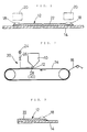
- Fig. 1 is a sectional view of the essential parts for explanation of the method of the present invention.
- Fig. 2 is a view showing the conception of the invented method.
- Fig. 3 is an enlarged sectional views of the essential parts showing the sectional form of the end portion of a synthetic resin film manufactured by the invented method.
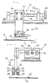
- Fig. 4 is a partially cutaway front elevation of a device for film end portion-treatment showing an embodiment of the invention.
- Fig. 5 is a sectional view of the invented device taken along the line V - V of Fig. 4.
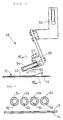
- Fig. 6 is partially cutaway front elevation of a device for film end portion-treatment showing another embodiment of the invention.
- Fig. 7 is a sectional view of the invented device taken along the line VII - VII of Fig. 7.
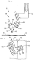
- Fig. 8 is a partially cutaway front elevation of a device for film end portion-treatment showing still another embodiment of the invention.
- Fig. 9 is a view taken in the direction of the arrow IX in Fig. 8.
- Fig. 10 consists of two views for illustration of the nozzle shown in Fig. 8, of which Fig. 10 (a) is a side sectional elevation and Fig. 10 (b) is a front elevation.
- Figs. 11 - 13 are views showing nozzles of different configurations, of which Fig. 11 is a partially cutaway side elevation, while Figs. 12 and 13 are front elevations.
- Figs. 14 - 16 are views showing other examples of the film end portion-treating device of the invention, of which Fig. 14 is a partially cutaway enlarged view of the essential parts showing a modification of the device of Fig. 5, while Figs. 15 and 16 are enlarged views showing the nozzle portion of the device of Fig. 6.
- Fig. 17 (a), (b), (c) are illustrative views showing different configurations of the nozzle aperture shown in Figs. 4, 6, 8 and 10 - 12.
- Fig. 18 is a schemative view for illustration of a conventional method of manufacturing a synthetic resin film.
- Fig. 19 is a sectional view of the essential parts showing the defect of the synthetic resin film manufactured by the conventional method.
- the synthetic resin film end portion-treating method of the present invention is aimed at modifying as desired the sectional form in the end portions of the synthetic resin film in the process of manufacture thereof by blowing a gas at both end portions of the fluid film of synthetic resin composition just formed by extrusion onto or coating on a conveyor belt or drum.
- the device of the invention for the synthetic resin film end portion-treatment by the aforementioned method comprises a pressure source and a single or plural nozzle/s for blowing at end portions of the fluid film of the synthetic resin composition just formed by extrusion onto or coated on the conveyor belt or drum a gas of a pressure higher than the atmospheric pressure (hereinafter called "high pressure gas”) led from the above-mentioned pressure source.
- high pressure gas a gas of a pressure higher than the atmospheric pressure
- the film end portion-treating method of the present invention consists in blowing a high pressure gas led from the pressure source through nozzle/s at the edge portions of the film of a fluid synthetic resin composition continuously extruded onto or coated on a conveyor belt or drum for modification as desired of the sectional form in the edge portions of the film thickened or increased in wall thickness due to the influence of surface tension etc. in the direction which can be changed as necessary by a direction changing means so as to have the film of a fluid synthetic resin composition closely fitted to the surface of the conveyor belt or drum.
- this method allows the film of a fluid synthetic resin composition to be solidified in the state closely fitted to the surface of the conveyor belt or drum, that is, with no indication of the edge portions lifting off and increase of the film's wall thickness in the end portions can be prevented without fail as well as sideway creasing in the same portions due to difference in shrinkage ratio.
- the numeral 10 represents a slit die, to which a fluid synthetic resin composition is supplied by a mixer (not shown) and this fluid synthetic resin composition is continuously extruded through the slid die 10.
- the extruded film 12 of a fluid synthetic resin composition is placed on an endless conveyor belt 14 circulating at the same as or higher than the extruding speed and the film 12 is then solidified on the conveyor belt 14.
- the fluidized resin composition is then solidified in film form on the conveyor belt by allowing or causing the solvent to evaporate when the fluid synthetic resin composition is acrylate resin, acetate resin, triacetate resin, imide resin etc., which are made into film form by the so-called solution casting method, or by cooling when it is a thermoplastic resin such as polyvinyl chloride resin, polyester resin or polystyrene resin.
- the solidified film 12 is peeled off the conveyor belt 14 as a synthetic resin film 16 and is rolled up on a roller after any aftertreatment as necessary.
- Both longitudinal end portions 18 of the film 12 of a fluid synthetic resin composition extruded onto the conveyor belt 14 are caused to be in a raised form as indicated by a two-dot chain line in Fig. 1 by the influence of surface tension or the like.
- the invented method consists in directing a gas flow from an end portion-treating device 20 at each of both end portions 18 to have the film 12 made thinner toward both ends with the sectional form thereof adjusted as desired.
- the sectional form in each of both end portions may be made concavo-convex or, as shown in Fig. 3, progressively smaller in height toward the end, and the film 12 is caused thereby to adhere closely to the conveyor belt 14 and also to be safe from sideway creasing due to difference in shrinkage ratio between the end portions and the portion in between.
- this end portion-treating device 20 comprises a pressure source 24 such as a gas bomb and an air reservoir, to which air is supplied compressed by a compressor or the like, a nozzle 28 to which the high pressure gas is supplied via a valve 26, and a flow direction changing means 30 to change the direction of the gas blown out through the nozzle 28.
- the pressure source 24 is for supplying a gas under a constant pressure (a pressure higher than the atmospheric pressure), and the valve 26 is for adjusting that constant gas pressure as necessary, at the same time controlling the pressure or flow rate of the gas being blown out through the nozzle 28.
- the end portion-treating device 20 is so arranged that its nozzle 28 and the direction changing means 30 are attached to a positioning device 32, as an example thereof is shown in Fig. 4 and Fig. 5.
- the positioning device 32 has screwed thereinto a pair of guide rods 34 and screws and is made up of a threaded member 38 rotated by a handle 36 attached to one end thereof and a moving member 40 which is caused to move along the guide rod 34 as the threaded member 38 rotates, so that the nozzle 28 and the direction changing means 30 are positioned immediately thereafter corresponding to the change in dimensions of the synthetic resin film 16 (film 12) to be manufactured.
- the nozzle 28 is formed as a slit and the gas is blown approximately perpendicularly downward as linear streams.
- a rectangular member 42 constituting the nozzle 28 has formed therein a groove 44, and it is so arranged that the rectangular member 42 can move with respect to the supporting member 46 to which it is attached.
- a pair of nozzles 28 are capable of changing the positions in the end portions of the film of a fluid synthetic resin composition 12 at which the gas streams are directed.
- an end portion-treating device 48 is fixedly secured to a supporting member 50 so formed that it can be attached to a positioning device at the desired angle.
- Nozzles 52 of the end portion-treating device 48 have their apertures formed on one side of a cylinder 54 as slits along its axis and, as shown in Fig. 7, there are arranged 4 nozzles 52.
- the cylinder 54 having the nozzles 52 formed therein is attached to a holding member 56 to be freely rotatable in the peripheral direction with respect thereto and, as shown in Fig. 7, it is so arranged that the direction of the gas streams out of the nozzles 52 can be properly set or adjusted.
- the width and length of the slit of the nozzle 52 may be made different from nozzle to nozzle, and it is also possible to have the pressure or flow rate of the high pressure air supplied to the individual nozzles 52 controllable by means of the valve 26.
- the gas streams can be directed freely for efficient blowing at the end portions 18, hence the sectional form of the end portions 18 can be made to be as desired. Moreover, the gas streams out through the nozzles 52 are undivergently directed at the end portions 18 of the film 12, and it is seldom the case that the flat portion 22 in between of the film 12 is affected thereby.
- a nozzle 60 of an end portion-treating device 58 is formed by cutting a cylinder 62 at one end diagonally, and forming a slit in the plate used for closing the cut end.
- the cylinder 62 is set through a bore 65 made through a holding member 64 to be freely rotatable and, after setting of the direction of the gas stream out of the nozzle 60, the cylinder 62 is fixed to the holding member 64 by means of screws 66.
- the holding member 64 is, as shown by the two-dot chain line in Fig. 9, is attached to an auxiliary member 68 secured to the holding member 50 to be freely rotatable with a screw 70 as the center, so that the gas streams out of the nozzles 60 are directed at the required positions of the edge portions 18 of the film 12.
- the angle of the nozzles 60 formed in the cylinder 62 is not necessarily as shown in Figs. 8 and 10 and, for instance, may be more gentle as shown in Fig. 11, or may as well be approximately 90 degrees against the nozzles 60 as in the preceding embodiment shown in Fig. 10 and, further, it is possible to make the nozzles 74 as small holes as shown in Fig. 13. Furthermore, it is also possible to properly combine various nozzles such as 60, 72 and 74.
- nozzles 80 consisting of small holes in the cylindrical member 78 and, as shown in Fig. 16, it is also possible to form a nozzle as a combination of slits and small holes.
- nozzle aperture in a single rectangular form but in desired forms as shown in Fig. 17 so as to make the sectional form of the end portions of the film 12 still closer to the desired one.
- the end portion-treating method for a synthetic resin film according to the invention as well as the device therefor consists of blowing a gas at the end portions of the film of a fluid synthetic resin composition for changing the sectional form of both end portions thereof, hence ensures against creasing or lifting off the conveyor belt etc. of the film and thus enables to manufacture a synthetic resin film superior in quality. Moreover, normally inevitable creasing in the end portions can be prevented without fail, hence there is no need of trimming off the end portions, this resulting in an improved yield and lowered manufacturing cost of any synthetic resin film.
Landscapes
- Engineering & Computer Science (AREA)
- Mechanical Engineering (AREA)
- Physics & Mathematics (AREA)
- Thermal Sciences (AREA)
- Extrusion Moulding Of Plastics Or The Like (AREA)
- Processing And Handling Of Plastics And Other Materials For Molding In General (AREA)
Claims (5)
- Procédé pour produire un film en résine synthétiquea) en produisant en continu une couche mince (12) d'une composition de résine synthétique fluide en extrudant la composition à travers une filière droite (10) ou en l'enduisant sur la surface d'une courroie transporteuse (14) ou d'un tambour;b) en soufflant du gaz sur les portions marginales latérales longitudinales (18) de la couche (12); etc) en solidifiant la couche (12),caractérisé en ce qued) à l'étape b), on dirige le gaz transversalement à la direction d'extrusion ou d'enduction et vers l'extérieur par rapport à la ligne médiane de la couche (12) en direction des deux portions marginales latérales longitudinales (18) de ladite couche (12).
- Appareil pour produire un film en résine synthétique, équipéa) d'un moyen d'extrusion pour extruder une composition de résine synthétique fluide sous la forme d'une couche mince (12) à travers une filière droite (10) ou d'un moyen d'enduction pour l'enduire en utilisant un dispositif d'enduction, sur la surface d'une courroie transporteuse (14) ou d'un tambour;b) d'une source de pression (24) équipée de tuyères (28, 52, 60, 72, 74, 80 ou 82) qui dirigent un gaz sous pression en direction des deux portions marginales latérales longitudinales (18) de la couche (12); et équipéc) d'un moyen pour solidifier la composition de résine de la couche (12); caractérisé en ce qued) les tuyères (28, 52, 60, 72, 74, 80, 82) sont dirigées transversalement à la direction d'extrusion ou d'enduction et vers l'extérieur par rapport à la ligne médiane de la couche (12) en direction des deux portions marginales latérales longitudinales (18) de la couche (12).
- Appareil selon la revendication 2, dans lequel les tuyères sont équipées d'un moyen de changement de direction pour modifier la direction du gaz sous haute pression provenant desdites tuyères (28, 52, 60, 72, 74, 80, 82).
- Appareil selon la revendication 2 ou 3, dans lequel les tuyères (28, 52, 60, 72, 74, 80, 82) sont façonnées en forme de fentes, de petits trous ou d'une combinaison de fentes et de petits trous.
- Appareil selon l'une quelconque des revendications 2 à 4, dans lequel ladite composition de résine synthétique fluide est une résine durcissante liquide à deux composants, une résine thermodurcissable ou une résine thermoplastique.
Applications Claiming Priority (2)
| Application Number | Priority Date | Filing Date | Title |
|---|---|---|---|
| JP63025387A JP2626783B2 (ja) | 1988-02-04 | 1988-02-04 | 樹脂フィルムの端部処理方法及び装置 |
| JP25387/88 | 1988-02-04 |
Publications (3)
| Publication Number | Publication Date |
|---|---|
| EP0327100A2 EP0327100A2 (fr) | 1989-08-09 |
| EP0327100A3 EP0327100A3 (en) | 1989-09-20 |
| EP0327100B1 true EP0327100B1 (fr) | 1993-09-08 |
Family
ID=12164466
Family Applications (1)
| Application Number | Title | Priority Date | Filing Date |
|---|---|---|---|
| EP89101888A Expired - Lifetime EP0327100B1 (fr) | 1988-02-04 | 1989-02-03 | Procédé et dispositif de fabrication de feuilles en matière synthétique |
Country Status (5)
| Country | Link |
|---|---|
| US (1) | US5030409A (fr) |
| EP (1) | EP0327100B1 (fr) |
| JP (1) | JP2626783B2 (fr) |
| CA (1) | CA1315060C (fr) |
| DE (1) | DE68908906T2 (fr) |
Cited By (1)
| Publication number | Priority date | Publication date | Assignee | Title |
|---|---|---|---|---|
| CN106079497A (zh) * | 2016-08-19 | 2016-11-09 | 昆山华富新材料股份有限公司 | 盐析法制备聚氨酯微孔薄膜的方法 |
Families Citing this family (12)
| Publication number | Priority date | Publication date | Assignee | Title |
|---|---|---|---|---|
| JPH02270526A (ja) * | 1989-04-13 | 1990-11-05 | Toray Ind Inc | 樹脂フィルム製造方法及び製造装置 |
| US5147595A (en) * | 1991-07-23 | 1992-09-15 | James River Ii, Inc. | Apparatus and method for reducing plastic film neck-in |
| US6117924A (en) * | 1996-10-22 | 2000-09-12 | Crane Plastics Company Limited Partnership | Extrusion of synthetic wood material |
| JP2000071268A (ja) * | 1998-08-31 | 2000-03-07 | Du Pont Toray Co Ltd | ポリイミドフィルムおよびその製造方法 |
| JP4641673B2 (ja) * | 2001-07-06 | 2011-03-02 | ユニチカ株式会社 | ポリアミドフィルムの製造方法 |
| JP2005349600A (ja) * | 2004-06-08 | 2005-12-22 | Sumitomo Chemical Co Ltd | 板厚精度の優れた樹脂板の製造方法 |
| EP1963920B1 (fr) * | 2005-12-21 | 2012-05-16 | FUJIFILM Corporation | Feuilles photosensibles et procede et appareil de fabrication de ces dernieres |
| CN102625567B (zh) * | 2007-07-09 | 2014-07-16 | 住友电木株式会社 | 用于电路板的树脂片及其生产方法 |
| US9315333B2 (en) * | 2010-09-09 | 2016-04-19 | Laitram, L.L.C. | System and method for measuring, mapping, and modifying the temperature of a conveyor |
| WO2012056619A1 (fr) * | 2010-10-26 | 2012-05-03 | コニカミノルタオプト株式会社 | Procédé de production d'un film de résine, matrice de coulée sous pression, dispositif de production d'un film de résine, film de résine, plaque polarisante, et dispositif d'affichage à cristaux liquides |
| US9162403B2 (en) | 2013-03-15 | 2015-10-20 | Davis-Standard, Llc | Apparatus for manufacturing and processing pre-stretch films having strips of increased thickness |
| CA2953375A1 (fr) * | 2017-01-03 | 2018-07-03 | Solmax International Inc. | Appareil et methode de fabrication de pellicules polymeres a epaisseur controlee, et pellicules polymeres ainsi produits |
Family Cites Families (12)
| Publication number | Priority date | Publication date | Assignee | Title |
|---|---|---|---|---|
| NL25255C (fr) * | 1928-09-06 | |||
| US3121915A (en) * | 1958-06-25 | 1964-02-25 | Nat Distillers Chem Corp | Art of extruding thermoplastic sheets |
| US3141194A (en) * | 1962-02-09 | 1964-07-21 | Avisun Corp | Gas delivery nozzle for film casting apparatus |
| US3597515A (en) * | 1969-01-22 | 1971-08-03 | Dow Chemical Co | Plastic extrusion process in chill roll casting of film for improved flatness |
| JPS4829859B1 (fr) * | 1970-06-11 | 1973-09-13 | ||
| DE2129147A1 (de) * | 1971-06-11 | 1973-01-04 | Olympia Werke Ag | Vorrichtung zum digitalen start-stopbetrieb streifenfoermiger aufzeichnungstraeger |
| JPS5226539B2 (fr) * | 1973-10-16 | 1977-07-14 | ||
| JPS5933096A (ja) * | 1982-08-17 | 1984-02-22 | Furukawa Electric Co Ltd:The | リン銅ロ−材及びその製造方法 |
| JPS59150727A (ja) * | 1983-02-17 | 1984-08-29 | Toray Ind Inc | 熱可塑性重合体シ−トの製造方法 |
| JPS6015118A (ja) * | 1983-06-28 | 1985-01-25 | ユニオン・カ−バイド・コ−ポレ−シヨン | Lldpe樹脂からフイルムを形成する際のエツジウエバ−の減少方法 |
| JPS62207624A (ja) * | 1986-03-07 | 1987-09-12 | Showa Denko Kk | 樹脂フイルムエツジブラスト方法およびその装置 |
| DE3702945A1 (de) * | 1987-01-31 | 1988-08-11 | Reifenhaeuser Masch | Vorrichtung zum glaetten einer aus einer schlitzduese austretenden kunststoffbahn |
-
1988
- 1988-02-04 JP JP63025387A patent/JP2626783B2/ja not_active Expired - Lifetime
-
1989
- 1989-02-02 CA CA000589915A patent/CA1315060C/fr not_active Expired - Fee Related
- 1989-02-03 EP EP89101888A patent/EP0327100B1/fr not_active Expired - Lifetime
- 1989-02-03 DE DE89101888T patent/DE68908906T2/de not_active Expired - Fee Related
- 1989-02-03 US US07/305,681 patent/US5030409A/en not_active Expired - Lifetime
Cited By (2)
| Publication number | Priority date | Publication date | Assignee | Title |
|---|---|---|---|---|
| CN106079497A (zh) * | 2016-08-19 | 2016-11-09 | 昆山华富新材料股份有限公司 | 盐析法制备聚氨酯微孔薄膜的方法 |
| CN106079497B (zh) * | 2016-08-19 | 2018-06-19 | 昆山华富新材料股份有限公司 | 盐析法制备聚氨酯微孔薄膜的方法 |
Also Published As
| Publication number | Publication date |
|---|---|
| US5030409A (en) | 1991-07-09 |
| CA1315060C (fr) | 1993-03-30 |
| JPH01200933A (ja) | 1989-08-14 |
| EP0327100A3 (en) | 1989-09-20 |
| DE68908906T2 (de) | 1994-01-05 |
| JP2626783B2 (ja) | 1997-07-02 |
| DE68908906D1 (de) | 1993-10-14 |
| EP0327100A2 (fr) | 1989-08-09 |
Similar Documents
| Publication | Publication Date | Title |
|---|---|---|
| EP0327100B1 (fr) | Procédé et dispositif de fabrication de feuilles en matière synthétique | |
| US4917844A (en) | Method of manufacturing laminate product | |
| EP0222510B1 (fr) | Appareil et méthode pour enduire des objets oblongs sous forme de feuille | |
| US4283168A (en) | Thermoplastic film extrusion apparatus | |
| US4255365A (en) | Pneumatic gauge adjustment of edge-pinned cast web | |
| JPH0570507B2 (fr) | ||
| CA1260330A (fr) | Methode de moletage hors contact pour le bobinage de pellicules thermoplastiques a module eleve | |
| EP0943961A2 (fr) | Appareil de couchage par rideau et procédé au réglage continu de la largeur | |
| US4548837A (en) | Method and apparatus for coating | |
| US20220097283A1 (en) | Automated mapping system for controlling parameters of polymeric melt | |
| JP3358849B2 (ja) | 長繊維強化熱可塑性樹脂組成物製造用被覆ダイ | |
| US5009831A (en) | Extrusion coated substrates with separable and removable layers | |
| JP3369910B2 (ja) | Tダイによる樹脂フィルムの偏肉自動制御方法 | |
| US5437546A (en) | Apparatus for cooling of a film, foil or sheet | |
| US4676943A (en) | Method and apparatus for producing longitudinally stretched thermoplastic film | |
| JPH0479290B2 (fr) | ||
| KR100490129B1 (ko) | 가구패널용 에지몰딩 스트립 제조장치 | |
| JP2659731B2 (ja) | 連続して走行する板状体の表面に塗料を塗布する方法 | |
| EP0051699B1 (fr) | Procédé pour ajuster pneumatiquement l'épaisseur d'un film coulé attaché aux marges | |
| JP3258931B2 (ja) | Tダイによるフィルム製造装置およびその方法 | |
| JPH065152Y2 (ja) | 熱可塑性シートの冷却装置 | |
| JPH0628261Y2 (ja) | 合成樹脂薄帯状物製造装置 | |
| JP3477882B2 (ja) | ダイコーティング方法 | |
| JPH02172558A (ja) | 塗布方法及び装置 | |
| JP3702042B2 (ja) | 押出成形用ダイ |
Legal Events
| Date | Code | Title | Description |
|---|---|---|---|
| PUAI | Public reference made under article 153(3) epc to a published international application that has entered the european phase |
Free format text: ORIGINAL CODE: 0009012 |
|
| PUAL | Search report despatched |
Free format text: ORIGINAL CODE: 0009013 |
|
| AK | Designated contracting states |
Kind code of ref document: A2 Designated state(s): BE DE FR GB IT |
|
| AK | Designated contracting states |
Kind code of ref document: A3 Designated state(s): BE DE FR GB IT |
|
| 17P | Request for examination filed |
Effective date: 19900223 |
|
| 17Q | First examination report despatched |
Effective date: 19900910 |
|
| GRAA | (expected) grant |
Free format text: ORIGINAL CODE: 0009210 |
|
| AK | Designated contracting states |
Kind code of ref document: B1 Designated state(s): BE DE FR GB IT |
|
| REF | Corresponds to: |
Ref document number: 68908906 Country of ref document: DE Date of ref document: 19931014 |
|
| ITF | It: translation for a ep patent filed | ||
| ET | Fr: translation filed | ||
| PLBE | No opposition filed within time limit |
Free format text: ORIGINAL CODE: 0009261 |
|
| STAA | Information on the status of an ep patent application or granted ep patent |
Free format text: STATUS: NO OPPOSITION FILED WITHIN TIME LIMIT |
|
| 26N | No opposition filed | ||
| PGFP | Annual fee paid to national office [announced via postgrant information from national office to epo] |
Ref country code: GB Payment date: 19950124 Year of fee payment: 7 |
|
| PGFP | Annual fee paid to national office [announced via postgrant information from national office to epo] |
Ref country code: FR Payment date: 19950210 Year of fee payment: 7 |
|
| PG25 | Lapsed in a contracting state [announced via postgrant information from national office to epo] |
Ref country code: GB Effective date: 19960203 |
|
| GBPC | Gb: european patent ceased through non-payment of renewal fee |
Effective date: 19960203 |
|
| PG25 | Lapsed in a contracting state [announced via postgrant information from national office to epo] |
Ref country code: FR Effective date: 19961031 |
|
| REG | Reference to a national code |
Ref country code: FR Ref legal event code: ST |
|
| PGFP | Annual fee paid to national office [announced via postgrant information from national office to epo] |
Ref country code: DE Payment date: 19980206 Year of fee payment: 10 |
|
| PGFP | Annual fee paid to national office [announced via postgrant information from national office to epo] |
Ref country code: BE Payment date: 19980417 Year of fee payment: 10 |
|
| PG25 | Lapsed in a contracting state [announced via postgrant information from national office to epo] |
Ref country code: BE Free format text: LAPSE BECAUSE OF NON-PAYMENT OF DUE FEES Effective date: 19990228 |
|
| BERE | Be: lapsed |
Owner name: KANEGAFUCHI KAGAKU KOGYO K.K. Effective date: 19990228 |
|
| PG25 | Lapsed in a contracting state [announced via postgrant information from national office to epo] |
Ref country code: DE Free format text: LAPSE BECAUSE OF NON-PAYMENT OF DUE FEES Effective date: 19991201 |
|
| PG25 | Lapsed in a contracting state [announced via postgrant information from national office to epo] |
Ref country code: IT Free format text: LAPSE BECAUSE OF NON-PAYMENT OF DUE FEES Effective date: 20050203 |