EP0327197A2 - E/A-Simulation - Google Patents
E/A-Simulation Download PDFInfo
- Publication number
- EP0327197A2 EP0327197A2 EP89300079A EP89300079A EP0327197A2 EP 0327197 A2 EP0327197 A2 EP 0327197A2 EP 89300079 A EP89300079 A EP 89300079A EP 89300079 A EP89300079 A EP 89300079A EP 0327197 A2 EP0327197 A2 EP 0327197A2
- Authority
- EP
- European Patent Office
- Prior art keywords
- interrupt
- processor
- instruction
- simulated
- hardware
- Prior art date
- Legal status (The legal status is an assumption and is not a legal conclusion. Google has not performed a legal analysis and makes no representation as to the accuracy of the status listed.)
- Granted
Links
Images




Classifications
-
- G—PHYSICS
- G06—COMPUTING OR CALCULATING; COUNTING
- G06F—ELECTRIC DIGITAL DATA PROCESSING
- G06F13/00—Interconnection of, or transfer of information or other signals between, memories, input/output devices or central processing units
- G06F13/10—Program control for peripheral devices
- G06F13/105—Program control for peripheral devices where the program performs an input/output emulation function
Definitions
- a manufacturer of processing systems would like to have a vast amount of software available to run on the processing system as soon as the new hardware for the processing system is announced into the market place.
- a customer would more likely invest in a new processing system if the customer knows that an abundant supply of software is already available for use.
- a second approach is to simulate the second processor through software.
- a software simulator provides a mechanism to run previously written software for one processor on a new processing system having a different processor.
- a software approach to simulation allows taking advantage of faster second processing systems as they evolve. It allows the use of multitasking capabilities of the operating system to provide multiple instances of the first processor.
- Some software simulators on the market today include SoftPC, by Insignia Solutions, and the Amiga Transformer by Simile Research Inc. for Commodore's Amiga (based on Motorola's 68000). Information on this system was published in the article "Amiga's Trump Card: IBM PC Emulation", AMIGA WORLD , Vol. 1, No. 2, November/December 1985. Phoenix Technologies also provided a simulator to simulate the Intel processor for the Apollo machine which has a Motorola 68000 processor.
- the Intel 80286 processor has a very rich instruction set in that it provides a wide variety of instructions. Each instruction is tailored specifically for a particular type of situation. Additionally each instruction may be able to do several operations.
- the ROMP processor in the RT PC has a reduced instruction set (RISC) processor which provides fewer instructions and less function per instruction. As each instruction in the Intel 80286 may be able to do several tasks, more instructions would be required with the ROMP RISC processor to accomplish the same tasks.
- RISC reduced instruction set
- the speed of a processor can be increased by simplifying the instruction set. Although more instructions are required, no additional time is consumed on complicated instructions while executing the more common and simpler tasks.
- a first generation simulator runs 50 to 100 host machine instructions per simulated instruction.
- a second generation simulator runs an average of 10 host machine instructions per simulated instruction.
- a simulator takes either 50 or 10 instructions to simulate one instruction on the simulated machine
- the second processor running the simulator must be either 50 or 10 times as fast respectively as the simulated machine to be comparable in performance. It is therefore desirable to further reduce the number of simulator instructions per each simulated or translated instruction than what has previously been accomplished in the art.
- the present invention also provides a data processing complex including a hardware processor and at least one hardware I/O device running an application written for a different hardware processor on a simulation of that processor, including, in order to simulate interrupt requests from the I/O device to the simulated processor, there is provided means for polling for an interrupt when an instruction transfers control dynamically in an application running on the simulated processor.
- the Intel 80286 processor which is being simulated in the preferred embodiment of this invention, cannot be interrupted as it is executing an instruction, the interrupt can come in and be recognised and serviced after each instruction. On a processing system simulator, it would be very time consuming to look for an interrupt after each instruction is executed, and then service the interrupt if the interrupt were pending.
- interrupts are checked after a block of code (i.e. instructions).
- the blocks of instructions are defined by a technique previously applied to compiler technology, and now applied to I/O simulation.
- a graph analysis of the processor's flow of instruction control for the application program is used to determine blocks of first processor instructions that can be easily and readily translated together into several second processor instructions. After the end of a block of instructions, the simulated interrupt controller is checked to verify whether an interrupt is pending.
- the simulator polls a halfword, which is two bytes of memory, with a single Load Half word instruction.
- a halfword which is two bytes of memory, with a single Load Half word instruction.
- Each of the bytes of the halfword has a separate meaning.
- One byte indicates whether the processor is currently enabled to service interrupts. This byte is only updated by the simulated processor. The other byte indicates whether an interrupt is being requested. This byte only gets updated by the simulated interrupt controller. If both bytes are zero, it means that the processor is enabled for interrupts and that an interrupt is being requested.
- the IBM RT PC simulates the IBM PC AT.
- An advantage of this preferred embodiment is that both the RT PC and the PC AT have an equivalent bus that allows adapters that were made for the PC AT to be used in the RT PC, if the system has the software to drive the adapters.
- a virtual interface would have to be written to the hardware. In the present invention, there is direct interface to the hardware.
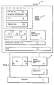
- the simulator 10 runs as an application program on the operating system 12 of the processing system 1.
- step 2 the simulator 10 copies BIOS 13 containing 80286 instructions from read only storage (ROS) 15, otherwise referred to as read only memory (ROM), into the operating system's 12 shared memory segment 16, step 3.
- the simulator 10 translates the BIOS 13, step 4, which loads the operating system (DOS) 18 for which the application 19 was originally written, step 5.
- the simulator 10 then translates and executes that operating system 18, step 6.
- a user invokes the application 19 at the operating system prompt, step 7, and the simulator 10 translates and executes the application program 19, step 8.
- a simulated interrupt controller routine 300 simulates the functions of a hardware interrupt mechanism, such as the Intel 8259, in order for a simulated CPU 10 to recognise and service a hardware interrupt from an adapter 310.
- the CPU simulator 10 can only receive one interrupt at a time since it is simulating the 286 processor which only allows one interrupt request to come in.
- a hardware interrupt controller called the 8259, was used to allow the 286 processor to receive only one interrupt, although 15 different levels of interrupts could be connected to internal adapters, such as the internal timer clock, or to external adapters, such as a communications card attached to the bus.
- the first processing system actually used two 8259 interrupt controllers with one cascaded into the other.
- Each of the interrupt controllers can receive eight inputs and prioritise them to one output.
- One interrupt controller receives eight interrupts from external or internal adapters, and prioritises them into one output.
- the other interrupt controller receives this one output as one of the interrupts along with seven other possible interrupts from external or internal devices.
- the simulated interrupt controller routine 300 is located in a shared memory segment 16 (Fig. 5) which allows applications and other processes 10, 9, and device drivers 320 (functioning as interrupt handlers) access to the emulated functions of the interrupt controller.
- the simulated interrupt controller routine 300 was written to be re-entrant in order for the routines to be called without synchronisation by other processes.
- Fig. 5 illustrates the preferred embodiment used by this invention to present actual hardware interrupts 315, 316, 317 to the CPU simulator 10, which is an application running on the operating system 12.
- VRM virtual resource manager
- the timer interrupt device driver 323 makes a call that sets a timer to receive periodic interrupts from the VRM 14. Each time a timer interrupt is received by the device driver 323 from the VRM 14, the device driver 323 calls the same interrupt controller simulation routine 300 to request an interrupt that the generic device driver 320 does when it receives an interrupt from the hardware 310. In this way, both timer interrupts 318 and hardware interrupts 319 can be sent to the simulator 10 which is running at the application level.
- Fig. 6 illustrates the steps used by the system Fig. 5 of this invention to present actual hardware interrupts 315, 316, 317 to the CPU simulator 10.
- an adapter 310 such as a 3278/3279 emulation card sends a hardware interrupt
- the device driver 320 recognises the interrupt 315, the device driver 320 calls a routine, the simulated interrupt controller routine 300, step 343, which simulates the functions of a hardware interrupt controller, e.g. the 8259, step 344.
- Some of these functions include checking the level of the interrupt, prioritising the interrupts, and checking for masked and unmasked interrupts.
- an application 19 can disable different levels of interrupts by masking interrupts. If an application 19 does not support certain I/O devices, it will mask the interrupts from them. Therefore, the simulated interrupt controller routine 300 will determine if an interrupt can be posted to the CPU simulator on the level that the device driver 320 received the interrupt on, step 345. If it cannot, it waits for the next call from a device driver 320-323.
- processors will recognise an interrupt when two conditions are true. One is that there is an interrupt being requested, in this case from the simulated interrupt controller routine. The other is that internally the processor is able to service the interrupt.
- the CPU simulator can disable interrupts, as most processors can. Usually this happens when the processor is dealing with very sensitive data that cannot be inconsistent. If a routine is updating data that is also dealt with in interrupt handlers, the processor will disable interrupts to guarantee that a certain sequence of instructions will be executed atomically without being interrupted.
- the processor indicates whether it can internally service an interrupt by updating the interrupt flag register in the processor.
- the processor indicates whether it can internally service an interrupt by updating the interrupt flag register in the processor.
- some typical instructions used by the processor to disable and enable interrupts through the flags register are described as follows.
- the CLI clears the interrupt enable bit in the flag register of the processor of first processing system being simulated to disable any interrupt requests from the interrupt controller.
- the STI set interrupt instruction sets the interrupt enable bit in the flag register to enable any interrupt requests from the interrupt controller.
- IRET there are two instructions, IRET and POPF, which replace the entire contents of the flag register including the interrupt enable bit.
- the CPU simulator 10 not only has to be able to recognise the fact that externally an interrupt action is being requested, but that internally the processor is able to service the interrupt. This is done by polling the two bytes 330 in the shared memory segment 16.
- the one byte 331 of the halfword 330 owned by the CPU would be zero if interrupts are enabled internally in the processor.
- the other byte 332 owned by the simulated interrupt controller routine 300 would be zero when an interrupt is being requested externally which is of high enough priority as determined by the current priority interrupt level of the simulated interrupt controller routine 300, step 344.
- the CPU simulator 10 regularly reads the two bytes 330, step 348, until the two bytes 330 become zero, step 349.
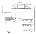
- a graph 30, Fig. 3, is built, step 133, Fig. 4, which represents the structure of the block of first processor instructions 100.
- Each node 101 in the graph corresponds to one instruction 100.
- a first processor instruction decoder 28 fills in each node 101 with information about the instruction 100 including the type 140 of instruction.
- the instruction type 140 is dependant on the number of descendants of an instruction 100.
- Each node 101 can have at most two descendants.
- sequential instructions 102-105, 107, 109, 111-113, 115-117 which transfer control only to the next sequential instruction in memory
- the nodes 101 have only one descendant 103-106, 108, 110, 112-114, 116-118, respectively, as shown in Fig. 3.
- the instruction 114, 118 that has no descendants illustrates an instruction that transfers control dynamically.
- a node 101 can have one descendant that is not the sequential instruction.
- the unconditional jump instruction 110 is an example of this.
- the nodes 101 are allocated in storage 120 sequentially as the translator 27, step 133, Fig. 4, finds them.
- the search through the application program 19 originally written for the first processor is called a depth first search.
- the depth first search means that the instructions are searched sequentially until an instruction is reached that has already been visited and stored in memory, e.g. move 104, or an end node such as zero, e.g. the return instruction 114, is reached. If an instruction (e.g. move 104) is reached that has already been stored in memory, and that instruction has a path 123 to the instruction previously stored (e.g.jump 110), then a loop has been encountered, and is recorded in the previously stored instruction (e.g. jump 110).
- step 136 the code generator 29 is invoked to translate the graph 30 into second processor instructions.
- the translator will insert translated code that checks for an interrupt at that point.
- the first byte in the halfword contains a zero when the processor is enabled to service interrupts.
- the second byte contains zero when an interrupt is being requested.
- These bytes can be updated atomically by using the STore Character instruction, and can be read simultaneously by using the Load Halfword instruction. This avoids synchronisation problems that occur when a program in a critical section is interrupted and another process updates the same data resulting in an inconsistent state.
- the CPU simulator 10 regularly reads the two bytes 330, step 348, until the two bytes 330 become zero, step 349.
- the CPU simulator 10 sends an interrupt acknowledge, step 350, to the simulated interrupt controller routine 300. This simulates the mechanism in the hardware by which the processor tells the interrupt controller that it has acknowledged the fact that the hardware has requested an interrupt.
- the simulated interrupt controller routine 300 returns the type of interrupt level, step 353, to the CPU simulator 10.
- the interrupt level information is passed by the simulated interrupt controller routine 300 in the form of an interrupt vector which indicates an address location in memory.
- the CPU simulator 10 receives this information, and goes to memory 16 and loads an address from that specified memory location to call an interrupt handler to process the interrupt.
- the interrupt handler processes IN and OUT instructions to the physical devices 11 to service the interrupt request.
- the interrupt handler completes, it notifies the simulated interrupt controller 300, and the simulated interrupt controller updates its internal status and performs the interrupt controller functions for an end of interrupt, step 354, 355 Fig. 6.
- the interrupt handler is part of the DOS 18 or BIOS 13 code that is used by the simulated processor. In this way, the CPU simulator 10 determines what needs to be done for each type of interrupt.
Landscapes
- Engineering & Computer Science (AREA)
- Theoretical Computer Science (AREA)
- Physics & Mathematics (AREA)
- General Engineering & Computer Science (AREA)
- General Physics & Mathematics (AREA)
- Debugging And Monitoring (AREA)
- Test And Diagnosis Of Digital Computers (AREA)
Applications Claiming Priority (2)
| Application Number | Priority Date | Filing Date | Title |
|---|---|---|---|
| US15112388A | 1988-02-01 | 1988-02-01 | |
| US151123 | 2002-05-17 |
Publications (3)
| Publication Number | Publication Date |
|---|---|
| EP0327197A2 true EP0327197A2 (de) | 1989-08-09 |
| EP0327197A3 EP0327197A3 (de) | 1991-07-03 |
| EP0327197B1 EP0327197B1 (de) | 1995-04-26 |
Family
ID=22537413
Family Applications (1)
| Application Number | Title | Priority Date | Filing Date |
|---|---|---|---|
| EP19890300079 Expired - Lifetime EP0327197B1 (de) | 1988-02-01 | 1989-01-05 | E/A-Simulation |
Country Status (3)
| Country | Link |
|---|---|
| EP (1) | EP0327197B1 (de) |
| JP (1) | JPH0677236B2 (de) |
| DE (1) | DE68922321T2 (de) |
Cited By (1)
| Publication number | Priority date | Publication date | Assignee | Title |
|---|---|---|---|---|
| EP0807882A3 (de) * | 1996-05-14 | 1998-04-15 | HE HOLDINGS, INC. dba HUGHES ELECTRONICS | Softwareinterpreter für Luftfahrtrechner |
Families Citing this family (2)
| Publication number | Priority date | Publication date | Assignee | Title |
|---|---|---|---|---|
| JP5045139B2 (ja) * | 2007-02-16 | 2012-10-10 | 富士通株式会社 | ソフトウェア生成装置及びシミュレーションシステム |
| WO2024195044A1 (ja) * | 2023-03-22 | 2024-09-26 | 三菱電機株式会社 | 割込み模擬装置、割込み模擬方法、及び割込み模擬プログラム |
Family Cites Families (2)
| Publication number | Priority date | Publication date | Assignee | Title |
|---|---|---|---|---|
| US4727480A (en) * | 1984-07-09 | 1988-02-23 | Wang Laboratories, Inc. | Emulation of a data processing system |
| JPS6446845A (en) * | 1987-08-18 | 1989-02-21 | Hitachi Ltd | Simulation system for microcomputer |
-
1988
- 1988-12-19 JP JP63318669A patent/JPH0677236B2/ja not_active Expired - Lifetime
-
1989
- 1989-01-05 EP EP19890300079 patent/EP0327197B1/de not_active Expired - Lifetime
- 1989-01-05 DE DE1989622321 patent/DE68922321T2/de not_active Expired - Fee Related
Cited By (2)
| Publication number | Priority date | Publication date | Assignee | Title |
|---|---|---|---|---|
| EP0807882A3 (de) * | 1996-05-14 | 1998-04-15 | HE HOLDINGS, INC. dba HUGHES ELECTRONICS | Softwareinterpreter für Luftfahrtrechner |
| US6564241B1 (en) | 1996-05-14 | 2003-05-13 | L-3 Communications Corporation | Avionic computer software interpreter |
Also Published As
| Publication number | Publication date |
|---|---|
| EP0327197A3 (de) | 1991-07-03 |
| JPH0677236B2 (ja) | 1994-09-28 |
| DE68922321T2 (de) | 1995-11-02 |
| EP0327197B1 (de) | 1995-04-26 |
| DE68922321D1 (de) | 1995-06-01 |
| JPH01205347A (ja) | 1989-08-17 |
Similar Documents
| Publication | Publication Date | Title |
|---|---|---|
| US5129064A (en) | System and method for simulating the I/O of a processing system | |
| EP0327196B1 (de) | Prozessorssimulation | |
| US4819234A (en) | Operating system debugger | |
| EP0327195B1 (de) | Prozessorssimulation | |
| US6895460B2 (en) | Synchronization of asynchronous emulated interrupts | |
| EP0213952A2 (de) | Rechnersystem zur Steuerung virtueller Maschinen | |
| JPH0887420A (ja) | プロセス・スレッドを管理する方法および装置 | |
| EP0588473B1 (de) | Verfahren und Einrichtung zur Emulation der Umgebung eines Mikroprozessors | |
| JPH05216689A (ja) | コンピュータ装置およびコンピュータ装置を動作させる方法 | |
| KR900004291B1 (ko) | 데이터 프로세서 | |
| KR920003044B1 (ko) | 가상 머신 시스템용의 게스트 머신 실행 제어 시스템 | |
| EP0327197B1 (de) | E/A-Simulation | |
| JP2991242B2 (ja) | マルチプロセッサコンピュータシステム使用方法 | |
| EP0327198B1 (de) | Prozessorsimulation | |
| US6263421B1 (en) | Virtual memory system that is portable between different CPU types | |
| Bass et al. | A perspective on microcomputer software | |
| JPH0552535B2 (de) | ||
| Hussein | Lecture notes on operating system | |
| Babaoglu et al. | The HOCA operating system specifications | |
| Nourse | Microsoft Windows network virtual device drivers in PATHWORKS for DOS | |
| Goldberg et al. | The PRIM System: An alternative architecture for emulator development and use | |
| Olbert | Extended control program support: VM/370: a hardware assist for the IBM virtual machine facility/370 | |
| Lewis | General purpose emulation using the Hewlett-Packard 2100 minicomputer | |
| Kobayakawa et al. | HI8-3X: A µITRON-Specification Realtime Operating System for H8/300 Series Microcontrollers | |
| Gregoretti | TOMP Software |
Legal Events
| Date | Code | Title | Description |
|---|---|---|---|
| PUAI | Public reference made under article 153(3) epc to a published international application that has entered the european phase |
Free format text: ORIGINAL CODE: 0009012 |
|
| AK | Designated contracting states |
Kind code of ref document: A2 Designated state(s): DE FR GB |
|
| 17P | Request for examination filed |
Effective date: 19891214 |
|
| PUAL | Search report despatched |
Free format text: ORIGINAL CODE: 0009013 |
|
| AK | Designated contracting states |
Kind code of ref document: A3 Designated state(s): DE FR GB |
|
| 17Q | First examination report despatched |
Effective date: 19930830 |
|
| GRAA | (expected) grant |
Free format text: ORIGINAL CODE: 0009210 |
|
| AK | Designated contracting states |
Kind code of ref document: B1 Designated state(s): DE FR GB |
|
| REF | Corresponds to: |
Ref document number: 68922321 Country of ref document: DE Date of ref document: 19950601 |
|
| ET | Fr: translation filed | ||
| PGFP | Annual fee paid to national office [announced via postgrant information from national office to epo] |
Ref country code: GB Payment date: 19951215 Year of fee payment: 8 |
|
| PGFP | Annual fee paid to national office [announced via postgrant information from national office to epo] |
Ref country code: DE Payment date: 19960126 Year of fee payment: 8 |
|
| PLBE | No opposition filed within time limit |
Free format text: ORIGINAL CODE: 0009261 |
|
| STAA | Information on the status of an ep patent application or granted ep patent |
Free format text: STATUS: NO OPPOSITION FILED WITHIN TIME LIMIT |
|
| 26N | No opposition filed | ||
| PG25 | Lapsed in a contracting state [announced via postgrant information from national office to epo] |
Ref country code: FR Effective date: 19960930 |
|
| REG | Reference to a national code |
Ref country code: FR Ref legal event code: ST |
|
| PG25 | Lapsed in a contracting state [announced via postgrant information from national office to epo] |
Ref country code: GB Effective date: 19970105 |
|
| GBPC | Gb: european patent ceased through non-payment of renewal fee |
Effective date: 19970105 |
|
| PG25 | Lapsed in a contracting state [announced via postgrant information from national office to epo] |
Ref country code: DE Effective date: 19971001 |