EP0327247A2 - Querschwellenbau - Google Patents
Querschwellenbau Download PDFInfo
- Publication number
- EP0327247A2 EP0327247A2 EP89300680A EP89300680A EP0327247A2 EP 0327247 A2 EP0327247 A2 EP 0327247A2 EP 89300680 A EP89300680 A EP 89300680A EP 89300680 A EP89300680 A EP 89300680A EP 0327247 A2 EP0327247 A2 EP 0327247A2
- Authority
- EP
- European Patent Office
- Prior art keywords
- insert
- sleeper
- slot
- concrete
- supporting mass
- Prior art date
- Legal status (The legal status is an assumption and is not a legal conclusion. Google has not performed a legal analysis and makes no representation as to the accuracy of the status listed.)
- Withdrawn
Links
- 241001669679 Eleotris Species 0.000 title claims abstract description 27
- 238000010276 construction Methods 0.000 title description 2
- 239000002184 metal Substances 0.000 claims abstract description 11
- 239000011440 grout Substances 0.000 claims abstract description 5
- 238000003780 insertion Methods 0.000 abstract description 2
- 230000037431 insertion Effects 0.000 abstract description 2
- 239000000945 filler Substances 0.000 description 5
- 230000000717 retained effect Effects 0.000 description 3
- 239000004593 Epoxy Substances 0.000 description 2
- 230000014759 maintenance of location Effects 0.000 description 2
- 229910001208 Crucible steel Inorganic materials 0.000 description 1
- 239000011398 Portland cement Substances 0.000 description 1
- 229910000831 Steel Inorganic materials 0.000 description 1
- 238000005266 casting Methods 0.000 description 1
- 230000003292 diminished effect Effects 0.000 description 1
- 230000004048 modification Effects 0.000 description 1
- 238000012986 modification Methods 0.000 description 1
- 239000010959 steel Substances 0.000 description 1
Images

Classifications
-
- E—FIXED CONSTRUCTIONS
- E01—CONSTRUCTION OF ROADS, RAILWAYS, OR BRIDGES
- E01B—PERMANENT WAY; PERMANENT-WAY TOOLS; MACHINES FOR MAKING RAILWAYS OF ALL KINDS
- E01B9/00—Fastening rails on sleepers, or the like
- E01B9/66—Rail fastenings allowing the adjustment of the position of the rails, so far as not included in the preceding groups
-
- E—FIXED CONSTRUCTIONS
- E01—CONSTRUCTION OF ROADS, RAILWAYS, OR BRIDGES
- E01B—PERMANENT WAY; PERMANENT-WAY TOOLS; MACHINES FOR MAKING RAILWAYS OF ALL KINDS
- E01B9/00—Fastening rails on sleepers, or the like
- E01B9/02—Fastening rails, tie-plates, or chairs directly on sleepers or foundations; Means therefor
- E01B9/28—Fastening on wooden or concrete sleepers or on masonry with clamp members
-
- E—FIXED CONSTRUCTIONS
- E04—BUILDING
- E04B—GENERAL BUILDING CONSTRUCTIONS; WALLS, e.g. PARTITIONS; ROOFS; FLOORS; CEILINGS; INSULATION OR OTHER PROTECTION OF BUILDINGS
- E04B1/00—Constructions in general; Structures which are not restricted either to walls, e.g. partitions, or floors or ceilings or roofs
- E04B1/38—Connections for building structures in general
- E04B1/41—Connecting devices specially adapted for embedding in concrete or masonry
- E04B1/4107—Longitudinal elements having an open profile, with the opening parallel to the concrete or masonry surface, i.e. anchoring rails
Definitions
- This invention relates to construction securing means, and although not so limited, is directed primarily to a railway sleeper, and has particular advantage in those sleepers wherein it is necessary to secure two lines which merge such that adjustment of rail position transversely of its longitudinal axis is a most desirable feature.
- the invention is also useful in various civil engineering applications.
- a concrete mass has an elongate metal insert embedded therein, the outer surface of the insert having a recess therein by which the insert is keyed into the concrete, and the inner surface defining an upwardly facing T-slot which contains a fastener retaining member, for example, a rail fastener retaining block or bolt.
- a fastener retaining member for example, a rail fastener retaining block or bolt.
- a sleeper can support a rail the transverse position of which is adjustable by sliding a rail fastener retaining block along the T-slot, and, after final positioning, locking in position by insertion of a grout in the T-slot.
- a concrete supporting mass comprises at least one metal insert embedded therein, the insert being elongate and having channel forming walls which terminate in facing flanges such that the inner surfaces of the walls define a T-slot, the outer surfaces of the walls defining recesses by which the insert is keyed to the supporting mass.
- the sleeper is provided with at least two metal inserts, each insert having surfaces defining an upwardly facing T-slot, and side walls having recesses therein by which the inserts are keyed, there being provided rail fastener retaining blocks each having a stem depending therefrom and terminating in a T-head.
- a concrete sleeper 10 is provided with at least two (herein three) cast steel inserts 11.
- Each insert 11 has an upper planar surface 12 which is coplanar with the upper surface of the concrete sleeper 10, and it has two side walls 13 each containing a recess 14 which provides keying means whereby the concrete can firmly retain the insert to the sleeper. Tests have proved that the retention is very great indeed.
- each insert 11 comprises facing flanges 19 which define a T-slot 15, and the inner surfaces of those flanges 19 where they open to the mouth of the T-slot support a T-head 16 of each of two respective fastener retaining blocks 17.
- the T-head 16 depends therefrom being spaced therefrom by means of a circular section stem 18, but in other respects the retaining blocks 17 are used in accordance with known art, being retained in position by means of resilient steel bars 20 of known type.
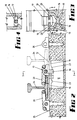
- Figs. 2, 3 and 4 show the above described sleeper assembly in some further detail, but in those Figs. the insert 11 is provided with two spaced abutment lugs 23 depending from each of the flanges 19 and these position the retaining blocks 17 either to hold the rail 24 against a left hand inserted shoulder 25 as shown in full lines, or, by merely rotating the retaining block 17 urging the rail 24 against the right hand shoulder 26 as shown in broken lines in Fig. 4.
- the shoulders 15 bear against the insert upper surface and the T-head bears against the under surfaces of flanges 19, also abutting lugs 23. This is of considerable value when it is desired to change a railroad track from broad gauge to narrow gauge or vice versa.
- the arrangement can also be used with some modification for supporting a secondary gauge rail, for example for use across a viaduct or bridge.
- FIG. 5 shows retaining bolt 28 having a head 29 adapted to bear against the flange 19, the bolt 28 having a shoulder 30 to constrain it against rotation.
- Fig. 6 illustrates a single casting 32 having two longitudinally spaced insert portions 33 joined by an intermediate portion 34 and this can be utilised in lieu of two separate inserts 11. These are of value particularly in turn out sleepers, and flat slab rail supports.
- the invention is not necessarily limited to railway blocks and can be used in such applications as securing columns to foundations in buildings, or aligning heavy presses or machine tools in factories, since the heavy articles can be inaccurately positioned and subsequently moved to final position where they can be firmly locked.
- the invention provides at least two very valuable advantages over prior art.
Landscapes
- Engineering & Computer Science (AREA)
- Architecture (AREA)
- Civil Engineering (AREA)
- Structural Engineering (AREA)
- Mechanical Engineering (AREA)
- Physics & Mathematics (AREA)
- Electromagnetism (AREA)
- Bridges Or Land Bridges (AREA)
- Machines For Laying And Maintaining Railways (AREA)
- Railway Tracks (AREA)
Applications Claiming Priority (2)
| Application Number | Priority Date | Filing Date | Title |
|---|---|---|---|
| AU6463/88 | 1988-01-28 | ||
| AUPI646388 | 1988-01-28 |
Publications (2)
| Publication Number | Publication Date |
|---|---|
| EP0327247A2 true EP0327247A2 (de) | 1989-08-09 |
| EP0327247A3 EP0327247A3 (de) | 1990-08-16 |
Family
ID=3772744
Family Applications (1)
| Application Number | Title | Priority Date | Filing Date |
|---|---|---|---|
| EP89300680A Withdrawn EP0327247A3 (de) | 1988-01-28 | 1989-01-25 | Querschwellenbau |
Country Status (5)
| Country | Link |
|---|---|
| US (1) | US4946099A (de) |
| EP (1) | EP0327247A3 (de) |
| CN (1) | CN1016806B (de) |
| AU (1) | AU630083B2 (de) |
| ZA (1) | ZA89543B (de) |
Cited By (4)
| Publication number | Priority date | Publication date | Assignee | Title |
|---|---|---|---|---|
| EP1700954A3 (de) * | 2004-12-23 | 2007-02-21 | SEAP Costruzioni Generali S.p.a. | Vorgefertigtes modulares Element, dieses Element einschließendes permanentes Tramwaygleis und unterirdisches Gleis, und Verfahren zu deren Auflegen |
| WO2022153046A1 (en) * | 2021-01-12 | 2022-07-21 | The Council Of The City Of Coventry | Rail support arrangement |
| GB2602688B (en) * | 2021-01-12 | 2024-05-29 | The Council Of The City Of Coventry | Railway infrastructure for a light rail system |
| EP4341490B1 (de) | 2021-05-17 | 2025-02-26 | Vossloh Cogifer | Anordnung mit mindestens einer schiene und einem träger |
Families Citing this family (17)
| Publication number | Priority date | Publication date | Assignee | Title |
|---|---|---|---|---|
| US5083706A (en) * | 1988-01-28 | 1992-01-28 | Amatek Limited | Concrete sleeper with east-in insert cooperating with a fastener assembly |
| US5221044A (en) * | 1991-12-19 | 1993-06-22 | Guins Sergei G | Rail fastening system with gage adjustment means |
| US5399057A (en) * | 1993-05-28 | 1995-03-21 | Cunic; Joseph M. | Self-locking lagging strip |
| US5485955A (en) * | 1994-07-11 | 1996-01-23 | Kerr-Mcgee Chemical Corporation | Rail-tie fastening assembly for concrete tie |
| GB2360539B (en) | 2000-03-24 | 2003-06-25 | Pandrol Ltd | Electrically insulating rail pad |
| US7237368B2 (en) * | 2002-05-24 | 2007-07-03 | Richard B. Richardson | Adjustable anchoring system for a wall |
| DE50304570D1 (de) * | 2003-01-28 | 2006-09-21 | Naumburger Bauunion Gmbh & Co | Verfahren zur herstellung einer festen schienenfahrbahn sowie feste schienenfahrbahn |
| DE102005057647A1 (de) * | 2005-12-01 | 2007-06-06 | Bwg Gmbh & Co. Kg | Betonschwelle |
| US7814710B2 (en) | 2006-01-26 | 2010-10-19 | Foglia Silvino R | Roof anchoring system |
| GB2554348B (en) * | 2016-09-13 | 2021-10-20 | Univ Nottingham | Tram, light rail and guided bus systems and components |
| US10370845B2 (en) * | 2017-03-08 | 2019-08-06 | Maestro International, Llc | Rotating pin locking connector |
| US10576658B2 (en) | 2017-05-15 | 2020-03-03 | Morton Buildings, Inc. | System and method for embedding substrate in concrete structure |
| US20180347208A1 (en) * | 2017-06-06 | 2018-12-06 | Dallas E. Myers | Window well system for poured concrete walls |
| CN109811599B (zh) * | 2019-03-21 | 2024-06-04 | 南京隆穹生物科技有限公司 | 一种盾构施工电瓶车跑道轨枕 |
| CN111102437A (zh) * | 2019-12-24 | 2020-05-05 | 中南林业科技大学 | 一种机架与地基连接安装方法及紧固件位置可调地基 |
| US12110678B2 (en) | 2020-07-09 | 2024-10-08 | Meadow Burke, Llc | Reinforcement for a connector in a precast concrete panel |
| CN114990941A (zh) * | 2022-06-08 | 2022-09-02 | 中车青岛四方机车车辆股份有限公司 | 一种轨距无级可调的轨道以及动调试验线 |
Family Cites Families (20)
| Publication number | Priority date | Publication date | Assignee | Title |
|---|---|---|---|---|
| US905867A (en) * | 1907-08-28 | 1908-12-08 | Wilfrid Joseph Girard | Track-fastening and tie. |
| FR433135A (fr) * | 1910-08-15 | 1911-12-26 | Leander Ekberg | Traverse de chemin de fer |
| US1018538A (en) * | 1911-09-11 | 1912-02-27 | William Wilde | Combined tie and rail-fastener. |
| US1588628A (en) * | 1922-11-02 | 1926-06-15 | Sellers Daniel Stewart | Hanger |
| US1667532A (en) * | 1926-10-01 | 1928-04-24 | Rockwood Sprinkler Co Massachusetts | Concrete hanger block |
| FR638730A (fr) * | 1927-08-02 | 1928-06-01 | Dispositif pour la fixation des rails sur les traverses en béton armé | |
| US1933536A (en) * | 1930-05-16 | 1933-11-07 | Floor Accessories Company Inc | Concrete insert |
| US2579373A (en) * | 1948-05-24 | 1951-12-18 | George G Edee | Rail chair |
| DE1137752B (de) * | 1960-05-12 | 1962-10-11 | Pius Swoboda | Schienenbefestigung auf Betonschwellen mittels Hakenschrauben |
| GB988860A (en) * | 1960-08-04 | 1965-04-14 | Eternit Spa | An improved electrical insulation device for railway lines |
| US3147921A (en) * | 1961-01-20 | 1964-09-08 | Frankignoul Pieux Armes | Device for fastening a rail to a concrete railway sleeper |
| US3282506A (en) * | 1963-12-18 | 1966-11-01 | Rails Co | Rail fastenings for concrete ties |
| US3858804A (en) * | 1972-08-28 | 1975-01-07 | Hixson R M | Rail fastening assembly |
| DE2324152C2 (de) * | 1973-05-12 | 1975-03-06 | Bochum-Gelsenkirchener Strassenbahnen Ag, 4630 Bochum | Befestigung für Schienen auf einem Betonunterbau und Vorrichtung und Verfahren zum Verlegen von Halterungen für die Befestigung |
| DE2409510A1 (de) * | 1974-02-28 | 1975-09-11 | Talke Kurt Prof Dr Ing | Schotterloser oberbau |
| DD114110A1 (de) * | 1974-08-28 | 1975-07-12 | ||
| DD116482A1 (de) * | 1974-11-13 | 1975-11-20 | ||
| CA1191123A (en) * | 1981-03-31 | 1985-07-30 | Lawrence W. Gray | Rail fastening |
| JPS5880401U (ja) * | 1981-11-26 | 1983-05-31 | 鉄道軌材工業株式会社 | レ−ルの締結装置 |
| US4756477A (en) * | 1987-07-24 | 1988-07-12 | Pandrol Limited | Plate for supporting railway rails and a track assembly using it |
-
1989
- 1989-01-19 AU AU28646/89A patent/AU630083B2/en not_active Expired
- 1989-01-24 US US07/301,620 patent/US4946099A/en not_active Expired - Fee Related
- 1989-01-24 ZA ZA89543A patent/ZA89543B/xx unknown
- 1989-01-25 EP EP89300680A patent/EP0327247A3/de not_active Withdrawn
- 1989-01-28 CN CN89100527A patent/CN1016806B/zh not_active Expired
Cited By (11)
| Publication number | Priority date | Publication date | Assignee | Title |
|---|---|---|---|---|
| EP1700954A3 (de) * | 2004-12-23 | 2007-02-21 | SEAP Costruzioni Generali S.p.a. | Vorgefertigtes modulares Element, dieses Element einschließendes permanentes Tramwaygleis und unterirdisches Gleis, und Verfahren zu deren Auflegen |
| WO2022153046A1 (en) * | 2021-01-12 | 2022-07-21 | The Council Of The City Of Coventry | Rail support arrangement |
| WO2022153049A1 (en) * | 2021-01-12 | 2022-07-21 | The Council Of The City Of Coventry | Method of installing a rail support arrangement |
| GB2618743A (en) * | 2021-01-12 | 2023-11-15 | The Council Of The City Of Coventry | Method of installing a rail support arrangement |
| GB2621708A (en) * | 2021-01-12 | 2024-02-21 | The Council Of The City Of Coventry | Rail support arrangement |
| US20240084514A1 (en) * | 2021-01-12 | 2024-03-14 | The Council Of The City Of Coventry | Rail support arrangement |
| GB2602688B (en) * | 2021-01-12 | 2024-05-29 | The Council Of The City Of Coventry | Railway infrastructure for a light rail system |
| GB2602673B (en) * | 2021-01-12 | 2024-05-29 | The Council Of The City Of Coventry | Railway infrastructure for a light rail system |
| GB2618743B (en) * | 2021-01-12 | 2024-06-05 | The Council Of The City Of Coventry | Railway Infrastructure For A Rail System |
| GB2621708B (en) * | 2021-01-12 | 2024-10-16 | The Council Of The City Of Coventry | Railway Infrastructure for a Light Rail System |
| EP4341490B1 (de) | 2021-05-17 | 2025-02-26 | Vossloh Cogifer | Anordnung mit mindestens einer schiene und einem träger |
Also Published As
| Publication number | Publication date |
|---|---|
| AU630083B2 (en) | 1992-10-22 |
| CN1036239A (zh) | 1989-10-11 |
| EP0327247A3 (de) | 1990-08-16 |
| AU2864689A (en) | 1989-08-10 |
| ZA89543B (en) | 1989-10-25 |
| US4946099A (en) | 1990-08-07 |
| CN1016806B (zh) | 1992-05-27 |
Similar Documents
| Publication | Publication Date | Title |
|---|---|---|
| EP0327247A2 (de) | Querschwellenbau | |
| US6257495B1 (en) | Device for securing railway rails on standard concrete sleepers in a highly resilient manner | |
| GB2087460A (en) | Rail clip anchorages | |
| US7658041B2 (en) | Anchoring for strip-shaped traction elements on supporting structures | |
| US4327865A (en) | Assembly for securing a rail to a supporting tie | |
| CN1425092A (zh) | 悬轨固定组件 | |
| EP0400081B1 (de) | Schiene-schwelle-befestigungssystem | |
| EP0738350B1 (de) | Eisenbahnschienenbefestigungsklammer, die gegen lösen und entfernen beständig ist | |
| JPH09316802A (ja) | レール締結装置、及びレール締結方法 | |
| JP2003074002A (ja) | レール締結装置、及びレール締結方法 | |
| US1065797A (en) | Concrete railway-tie. | |
| JPS61176705A (ja) | 床版の敷設工法 | |
| CA2943129C (en) | Hot forged tie plate for railroad | |
| JP3447186B2 (ja) | 合成まくら木 | |
| GB2108410A (en) | Baseplates for receiving railway rails | |
| US1214245A (en) | Railroad-tie. | |
| US18494A (en) | Construction of railways | |
| CA1288082C (en) | Removable self-retaining shoulder block for fastening rails to concrete ties | |
| US930437A (en) | Rail-tie and fastener. | |
| JPH086082Y2 (ja) | レールの弾性締結構造 | |
| US762944A (en) | Rail-tie and fastener. | |
| US1089861A (en) | Rail-fastening means. | |
| US1003113A (en) | Rail-fastener. | |
| US793082A (en) | Rail-clamping device. | |
| US980058A (en) | Metallic railway-tie and fastener. |
Legal Events
| Date | Code | Title | Description |
|---|---|---|---|
| PUAI | Public reference made under article 153(3) epc to a published international application that has entered the european phase |
Free format text: ORIGINAL CODE: 0009012 |
|
| AK | Designated contracting states |
Kind code of ref document: A2 Designated state(s): DE FR GB |
|
| PUAL | Search report despatched |
Free format text: ORIGINAL CODE: 0009013 |
|
| AK | Designated contracting states |
Kind code of ref document: A3 Designated state(s): DE FR GB |
|
| STAA | Information on the status of an ep patent application or granted ep patent |
Free format text: STATUS: THE APPLICATION IS DEEMED TO BE WITHDRAWN |
|
| 18D | Application deemed to be withdrawn |
Effective date: 19910219 |