EP0327372A1 - Piezoelektrischer Vibrationserreger und Förderer von Gegenständen mit einem solchen Erreger - Google Patents
Piezoelektrischer Vibrationserreger und Förderer von Gegenständen mit einem solchen Erreger Download PDFInfo
- Publication number
- EP0327372A1 EP0327372A1 EP89301026A EP89301026A EP0327372A1 EP 0327372 A1 EP0327372 A1 EP 0327372A1 EP 89301026 A EP89301026 A EP 89301026A EP 89301026 A EP89301026 A EP 89301026A EP 0327372 A1 EP0327372 A1 EP 0327372A1
- Authority
- EP
- European Patent Office
- Prior art keywords
- resilient plate
- parts feeder
- plate members
- vibration generator
- plate member
- Prior art date
- Legal status (The legal status is an assumption and is not a legal conclusion. Google has not performed a legal analysis and makes no representation as to the accuracy of the status listed.)
- Granted
Links
Images




Classifications
-
- B—PERFORMING OPERATIONS; TRANSPORTING
- B65—CONVEYING; PACKING; STORING; HANDLING THIN OR FILAMENTARY MATERIAL
- B65G—TRANSPORT OR STORAGE DEVICES, e.g. CONVEYORS FOR LOADING OR TIPPING, SHOP CONVEYOR SYSTEMS OR PNEUMATIC TUBE CONVEYORS
- B65G27/00—Jigging conveyors
- B65G27/10—Applications of devices for generating or transmitting jigging movements
- B65G27/16—Applications of devices for generating or transmitting jigging movements of vibrators, i.e. devices for producing movements of high frequency and small amplitude
- B65G27/18—Mechanical devices
-
- B—PERFORMING OPERATIONS; TRANSPORTING
- B65—CONVEYING; PACKING; STORING; HANDLING THIN OR FILAMENTARY MATERIAL
- B65G—TRANSPORT OR STORAGE DEVICES, e.g. CONVEYORS FOR LOADING OR TIPPING, SHOP CONVEYOR SYSTEMS OR PNEUMATIC TUBE CONVEYORS
- B65G27/00—Jigging conveyors
- B65G27/08—Supports or mountings for load-carriers, e.g. framework, bases, spring arrangements
-
- B—PERFORMING OPERATIONS; TRANSPORTING
- B06—GENERATING OR TRANSMITTING MECHANICAL VIBRATIONS IN GENERAL
- B06B—METHODS OR APPARATUS FOR GENERATING OR TRANSMITTING MECHANICAL VIBRATIONS OF INFRASONIC, SONIC, OR ULTRASONIC FREQUENCY, e.g. FOR PERFORMING MECHANICAL WORK IN GENERAL
- B06B1/00—Methods or apparatus for generating mechanical vibrations of infrasonic, sonic, or ultrasonic frequency
- B06B1/02—Methods or apparatus for generating mechanical vibrations of infrasonic, sonic, or ultrasonic frequency making use of electrical energy
- B06B1/06—Methods or apparatus for generating mechanical vibrations of infrasonic, sonic, or ultrasonic frequency making use of electrical energy operating with piezoelectric effect or with electrostriction
- B06B1/0607—Methods or apparatus for generating mechanical vibrations of infrasonic, sonic, or ultrasonic frequency making use of electrical energy operating with piezoelectric effect or with electrostriction using multiple elements
Definitions
- the present invention relates to a piezoelectric vibration generator having piezoelectric elements attached to opposite surfaces or sides of a resilient plate for generating slight vibratory motion, and also to a vibratory parts feeder incorporating such piezoelectric vibration generator for feeding small parts or articles in a predetermined supplying direction.
- Typical piezoelectrically driven vibratory parts feeders of the type described are disclosed in Japanese Patent Laid-open Publication (JP-A) No. 62-4118, 62-4119 and 62-4120.
- the disclosed parts feeders include a base and a vibratory conveyor table supported on the base by means of a plurality of properly spaced apart and obliquely disposed piezoelectric vibration generators.
- Each of the piezoelectric vibration generators comprises a leaf spring secured at a lower end to the base and carrying on its opposite surfaces a pair of piezoelectric elements, and an elongate resonant or amplitude enhancing member extending continuously and upwardly from the upper end of the leaf spring and secured at its upper end to the vibratory conveyor table.
- the amplitude enhancing member has a stiffness smaller than the stiffness of the leaf spring and hence is bendable easier than the leaf spring.
- the leaf spring is caused to shorten and lengthen alternately, thus producing longitudinal vibrations whose amplitude is in turn enhanced by the amplitude enhancing member.
- the thus enhanced vibratory impulses are imparted to the vibratory conveyor table, causing small parts or articles to move in a predetermined supplying direction along a path defined on the upper surface of the covnveyor table.
- the amplitude enhancing member is formed either as a separate connecting member which is structurally independent of the leaf spring, or as an upper extension of the leaf spring which is integral with the leaf spring.
- the amplitude enhancing member With the provision of the amplitude enhancing member, relatively large vibratory impulses can be imparted to the vibratory conveyor table. However, the amplitude of vibrations thus obtained is still limited to a certain level as the overall length of the vibration generator is determined depending upon the distance between the base and the vibratory conveyor table. It is therefore likely to occur that a desired amplitude of vibration cannot be produced from the prior art vibration generator.
- Another difficulty associated with the prior art vibratory parts feeder is that the amplitude enhancing member, which extends upwardly from the upper end of the leaf spring and has a smaller stiffness than the leaf spring, must be rigid enough to withstand the loads imparted thereon from the vibratory conveyor table.
- the stiffness of the amplitude enhancing member is inversely proportionate to the amplitude of vibrations produced from the vibration generator, setting of the amplitude of vibrations requires a fine adjustment of the stiffness of the amplitude enhancing member, which is tedious and time-consuming.
- the prior art vibratory parts feeder is relatively large in height as the leaf spring and the amplitude enhancing member extend linearly between the base and the vibratory conveyor table.
- the present invention seeks to provide a piezoelectric vibration generator for a vibratory parts feeder, which is capable of producing a desired amplitude of vibrations irrespective of the distance between a base and a vibratory conveyor table of the parts feeder.
- the present invention further seeks to provide a piezoelectric vibration generator which is rigid enough to withstand the loads imparted thereon from the vibratory conveyor table of a vibratory parts feeder incorporating the vibration generator.
- the present invention further seeks to provide a piezoelectric vibration generator for a vibratory parts feeder, which is small in height and hence is capable of reducing the overall height of the vibratory parts feeder.
- the present invention further seeks to provide a piezoelectric vibration generator for producing slight vibrations whose amplitude can be adjusted easily without the necessity of a fine adjustment of the stiffness of the vibration generator.
- the present invention further seeks to provide a piezoelectrically driven vibratory parts feeder which is relatively low in height and can easily be incorporated in a processing machine.
- a piezoelectric vibration generator comprising: at least two resilient plate members joined together at their one ends and disposed in a configuration substantially folded about the joint therebetween; and a pair of piezoelectric elements attached respectively to front and back surfaces of one of the resilient plate members.
- a piezoelectrically driven vibratory parts feeder comprising: a stationary base; a vibratory conveyor table; and at least one piezoelectric vibration generator interconnecting the base and the vibratory conveyor table and operable to impart vibratory impulses to the vibratory conveyor table, the piezoelectric vibration generator including at least two resilient plate members joined together at their one ends and disposed in a configuration substantially folded about the joint therebetween with their opposite ends directed upwardly, the opposite end of one of the resilient plate members being firmly connected to the base, the opposite end of the other resilient plate member being firmly connected to the vibratory conveyor table, and a pair of piezoelectric elements attached respectively to front and back surfaces of one of the resilient plate members.
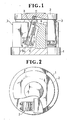
- Figures 1 and 2 show a piezoelectrically driven vibratory parts feeder incorporating piezoelectric vibration generators according to the present invention.
- the illustrated parts feeder is of the vibratory feeder bowl type but the present invention is also applicable to a vibratory parts feeder of the linear vibratory feeder type.
- the vibratory parts feeder includes a circular stationary base 1 and a circular vibratory conveyor table 2 disposed above the base 1 and supporting thereon a parts feeder bowl (not shown), and a plurality (four in the illustrated embodiment) of piezoelectric vibration generators 3 disposed between the base 1 and the vibratory conveyor table 2 and circumferentially spaced at equal angular intervals.
- Each of the piezoelectric vibration generators 3 includes a pair of parallel spaced first and second elongate resilient plate members 5, 10 extending obliquely with respect to the vertical, and a pair of piezoelectric elements 7, 8 attached to opposite surfaces or sides of the first resilient plate member 5.
- the first and second resilient plate members 5, 10 comprise leaf springs formed of flat rectangular plates of metal or synthetic resin.
- the first resilient plate member 5 has an upper end firmly secured by a pair of screws 6 to the upper end of an upstanding support bracket 4 which extends upwardly from the base 1 toward the vibratory conveyor table 2 and terminates short of the underside of the vibratory conveyor table 2.
- the lower end of the first resilient plate member 5 is firmly connected by screws 9 to the lower end of the second resilient plate member 10 with a spacer block 9a disposed between the respective lower ends of the first and second resilient plate members 5, 10.
- the second resilient plate member 10 is firmly secured at its upper end to the underside of the vibratory conveyor table 2 by means of screws 11.
- the first and second resilient plate members 5, 10 are disposed in face to face confrontation to one another.
- the piezoelectric vibration generator 3 has a substantially U-shaped configuration which is folded about the joint between the first and second resilient plate members 5, 10.
- the second resilient plate member 10 is longer than the first resilient plate member 5 and also thinner than the first resilient plate member 5.
- the first and second resilient plate members 5, 10 may have the same thickness.
- the piezoelectric elements 7, 8 may be attached to the second resilient plate member 10.
- an alternating voltage is applied to the piezoelectric elements 7, 8 to shorten and lengthen the piezoelectric elements 7, 8 and, consequently, the first resilient plate member 5, thereby producing slight longitudinal vibrations on the first resilient plate member 5.
- the thus produced longitudinal vibrations are amplified or enhanced by the second resilient plate member 10 and then imparted to the vibratory conveyor table 2, thereby causing small parts or articles to move upwardly along a helical spiral feed path or track provided in the non-illustrated vibratory feeder bowl.
- the amplitude of vibrations to be imparted to the vibratory conveyor table 2 can be adjusted accurately and easily by changing the length and the thickness of the second resilient plate member 10.
- the second resilient plate member 10 may be notched when a fine adjustment of the amplitude of vibrations is necessary.
- the vibration generator 3 Since the vibration generator 3 has a folded configuration, the overall length or longitudinal extent of the vibration generator 3 is relatively small. Consequently, a substantial reduction of the overall height of the vibratory parts feeder can be attained. Furthermore, loads acting on the second resilient plate member 10 are efficiently absorbed by such folded configuration of the vibration generator 3 and hence the vibration generator 3 is subjected to only a small bending moment.
- the vibration genrator 3 is therefore durable in construction.
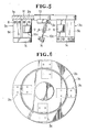
- a modified vibratory parts feeder shown in Figure 3 is substantially the same in structure and operation as the vibratory parts feeder shown in Figure 1 with the exception that each piezoelectric vibration generator 3a is formed of a single flat rectangular plate bent into a substantially U shape. First and second resilient plate members 5a, 10a of the vibration generator 3a are integrally joined at their lower ends.
- the vibration generator 3a is simple in construction and can be manufactured at a low cost.
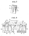
- FIG 4 shows a piezoelectric vibration generator 3b incorporated in a similar vibratory parts feeder.
- the vibration generator 3b is similar to the vibration generator 3 shown in Figure 1 but differs therefrom in that first and second resilient plate members 5b, 10b are directly connected together at their lower ends and they extend at an angle to one another.
- the vibration generator 3b has a substantially V shape folded or bent about the joint between the first and second resilient plate members 5b, 10b.
- the angle of inclination of the second resilient plate member 10b is determined on consideration of the angle of inclination of a helical spiral feed path provided in a parts feeder bowl (not shown) carried on the vibratory conveyor table 2.
- a modified piezoelectrically driven vibratory parts feeder shown in Figures 5 and 6 includes a ring-shaped stationary base 1a and a circular vibratory conveyor table 2a supported within a circular central opening of the ring-shaped base 1a by means of a plurality of piezoelectric vibration generators 3c.
- the base 1a and the vibratory conveyor table 2a lie in the same horizontal plane.
- the piezoelectric vibration generators 3c are disposed concentrically around the center of the vibratory conveyor table 2a at equal circumferential intervals as shown in Figure 6 and interconnect the base 1a and the vibratory conveyor table 2a.
- Each of the piezoelectric vibration generators 3c comprises a pair of parallel spaced first and second elongate resilient plate members 5c, 10c extending obliquely with respect to the vertical, and a pair of piezoelectric elements 7, 8 attached to opposite surfaces or sides of the second resilient plate member 10c.
- the first and second resilient plate members 5c, 10c have the same length and the same thickness and each plate member 5c, 10c comprises a leaf spring formed of a flat rectangular plate of metal or synthetic resin.
- the first resilient plate member 5c is firmy secured at its upper end to the underside of the base 1a by means of screws 6.
- the lower end of the first resilient plate member 5c is firmly connected to the lower end of the second resilient plate member 10c via a connector plate 14.
- the upper end of the second resilient plate member 10c is firmy secured by screws 11 to a mounting bracket 13 which is firmly connected to the underside of the vibratory conveyor table 2a.
- the first and second resilient plate members 5c, 10c are disposed in side by side juxtaposition to one another.
- the vibration generator 3c has a substantially U-shaped configuration bent or folded about the joint between the first and second resilient plate members 5c, 10c.
- the vibratory parts feeder operates in the same manner as the vibratory parts feeder of the preceding embodiments shown in Figures 1 through 4.
- this vibratory parts feeder is substantially flat and low in profile and hence can be easily incorporated in various processing machines.
- FIG 7 shows a modified piezoelectric vibration generator 3d which can be used in place of the vibration generator 3c shown in Figure 5.
- This vibration generator 3d is substantially the same as the vibration generator 3c exceping that the vibration generator 3d is formed of a single flat plate stamped into a U shape.
- a pair of parallel juxtaposed first and second resilient plate members 5d, 10d of the vibration generator 3d are joined integrally at their lower ends. With this integral formation of the first and second resilient plate members 5d, 10d, the vibration generator 3d is simple in construction and can be manufactured less costly.
- a modified vibratory parts feeder shown in Figure 8 is similar to the vibratory parts feeder shown in Figure 5 but differs therefrom in that a stationary base 1b and a vibratory conveyor table 2a are both circular in shape and the vibratory conveyor table 2a is supported in a horizontal plane slightly above the base 1b.
- the base 1b has a plurality of openings or apertures 16 circumferentially spaced at equal angular intervals.
- the vibratory parts feeder further includes a plurality of piezoelectric vibration generators 3e corresponding in number to the number of the apertures 16 in the base 1b and disposed in respective positions corresponding to the respective positions of the apertures 16.
- Each of the piezoelectric vibration generators 3e is composed of a first resilient plate member 5e and two identical second resilient plate members 10e, 10e disposed on opposide sides of the first resilient plate member 5e in side by side juxtaposition with respect to the first resilient plate member 5e.
- the respective upper ends of the second resilient plate members 10e, 10e are firmly secured to the underside of the base 1b at positions which are located on diametrically opposite sides of the corresponding one of the apertures 16.
- the respective lower ends of the second resilient plate members 10e are firmly secured to a rectangular connector plate 5e to which the lower end of the first resilient plate member 5e is also firmly secured.
- the first resilient plate member 5e extends upwardly through the corresponding aperture 16 and firmly secured at its upper end to the underside of the vibratory conveyor table 2a.
- the first resilient plate member 5e carries on its opposite surfaces or sides a pair of piezoelectric elements 7, 8.
- the piezoelectric elements 7, 8 may be attached to at least one of the second resilient plate members 10e, 10e.
- the first and second resilient plate members 5e, 10e may be united into integral formation in such a manner as the same as the piezoelectric vibration generator 3d shown in Figure 7.
- the vibration generator having a folded configuration is capable of producing a desired amplitude of vibrations irrespective of the distance between the base and the vibratory conveyor table.
- FIGs 9 and 10 show a modified vibratory parts feeder according to the present invention.
- the parts feeder includes a horizontal base 17 firmly connected to the upper end of a vertical supporting post 18, a circular vibratory conveyor table 19 disposed above the base 17 and carrying thereon a parts feeder bowl 20, and a plurality (four in the illustrated embodiment) of piezoelectric vibration generators 3f interconnecting the base 17 and the vibratory conveyor table 19.
- the base 17, as shown in Figure 10, is in the shape of a windmill having four identical rectangular wings 17a.
- Each of the piezoelectric vibration generators 3f includes a vertically disposed first resilient plate member 5f firmly connected at its upper end to one of two adjacent sides of each respective rectangular wing 17a, and an obliquely disposed second resilient plate member 10f connected at its lower end to the lower end of the first resilient plate member 5f via a rectangular connector block 21, the upper end of the second resilient plate member 10f being firmly secured to the peripheral surface of the circular vibratory conveyor table 18.
- the first resilient plate member 5f carries on its opposite surfaces or sides a pair of piezoelectric elements 7, 8.
- attachment of the upper end of the first resilient plate member 5f to the base 17 is performed by means of a pair of screws 22 which pass successively through spring washers 23, washers 24, holes in a presser plate 25, and holes in the plate member 5f and are threaded into threaded holes in the base 17.
- the lower end of the plate member 5f is connected to the connector block 21 by a pair of screws 26 that pass successively through spring washers 23, washers 24, holes in another presser plate 25, holes in the plate member 5f, and transverse holes in the connector block 21 and are threaded into threaded hoels in a retainer plate 27.
- the retainer palte 27 may be omitted when the transverse holes in the connector block 21 are internally threaded.
- the connector block 21 further has a threaded longitudinal hole 28 into which a screw 29 is threaded to attached the lower end of the second resilient plate member 10f to the connector block 21.
- the screw 29 passes successively through a spring washer 23, a washer 24, a hole in the presser plate 30, and a lower hole in the second resilient plate member 10f.
- the upper end of the second resilient plate member 10f is secured by a screw 29 that passes through a spring washer 23, a washer 24, a hole in another presser plate 30, and an upper hole in the plate member 10f.
- Each of the first and second resilient plate members 5f, 10f is formed of a flat rectangular resilient plate of metal or synthetic resin.
- the second resilient plate member 10f lies in a vertical plane extending tangentially with respect to the peripheral surface of the circular vibratory conveyor table 19.
- the first resilient plate member 5f lies in a plane extending at an angle ⁇ of about 90 degrees, as shown in Figure 10. This angle ⁇ can be varied by displacing the first resilient plate member 5f along the side of the rectangular wing 17a. When the first resilient plate member 5f is displaced inwardly of the base 17, the angle ⁇ becomes greater than 90 degrees. Conversely, the angle ⁇ becomes smaller than 90 degrees as the plate member 5f is displaced outwardly of the base 17. The adjustment of the angle ⁇ is performed in such a manner as to enable the second resilient plate member 10f to be attached to the peripheral surface of the circular vibratory conveyor table 19.
- the second resilient plate member 10f is inclined with respect to the vertical (indicated by the phantom line L) at an angle of ⁇ .
- This angle ⁇ is nearly equal to the angle of inclination of a helical spiral feed path or track provided in the parts feeder bowl 20 but, in practice, it is experimentally determined with reference to the angle of inclination of the helical spiral feed path.
- the angle ⁇ can be varied either by changing the length of the second resilient plate member 10f, by displacing the position of the joint between the first and second resilient plate members 5f, 10f inwardly or outwardly of the base 17, or by displacing the first resilient plate member 5f inwardly or outwardly of the base 17.
- the change of the length of the second resilient plate member 10f can be achieved simply by replacing the plate member 10f with another plate member whose length is different to the length of the plate member 10f.
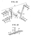
- a second resilient plate member which is adjustable in length such as shown in Figures 12 and 13.
- the plate member 10f′ shown in Figure 12 includes a channel shaped elongate holder 31 adapted to be connected at its one end to the vibratory conveyor table 19 ( Figure 9), and an elongate slide 32 slidably received in a longitudinal guide channel in the holder 31 and having a longitudinal groove 33.
- a lock screw 34 passes through a longitudinal slot in the holder 31 and through the longitudinal groove 33 in the slide 32 and is threaded into a threaded hole (not shown) formed in the bottom wall of the holder 31.
- the slide 32 is movable along the guide channel in the holder 31 to thereby change the overall length of the plate member 10f′.
- the slide 32 is locked in position against displacement by tightening the screw 34 until the slotted upper wall of the holder 31 is resiliently flexed inwardly toward the bottom wall, thus gripping the slide 32 by and between the upper and bottom walls of the holder 31.
- a modified second resilient plate member 10f ⁇ shown in Figure 13 includes a pair of flat rectangular plate elements 35, 35 interconnected at their one ends by a stud screw 36.
- the overall length of the plate member 10f ⁇ can be varied by turning at least one plate element 35 in either direction.
- Figures 14 and 15 show the manner in which the position of the joint between the first and second resilient plate members 5f, 10f is displaced inwardly and outwardly with respect to the vertical support post 18 for adjustably changing the angle of inclination of the second resilient plate member 10f.
- the adjustment of this inclination angle is achieved by utilizing a mounting bracket 37 which is detachably connected by screws 38 to the base 17 and to which the upper end of the first resilient plate member 5f is firmly secured.
- the mounting bracket 37 has a length L1 as shown in Figure 16A.
- the mounting bracket 37 is replaced by another mounting bracket 39 which has a smaller length L2 than the mounting bracket 37, as shown in Figure 16B.
- the mounting bracket 37 may be replaced with a mounting bracket 40 having a sloped surface 41 on which one side of the first resilient plate member 5f is disposed flatwise when the plate member 5f is connected at its upper end to the base 17.
- the vibratory parts feeders shown in Figures 9 through 15 not only possess the same advantages as those attained by the vibratory parts feeders shown in Figures 1 throgh 6 and 8, but also are advantageous over the latter-mentioned vibratory parts feeders in that when an adjustment of the amplitude and direction of vibrations is necessary, the angle of inclination of the second resilient plate member 10f can be easily adjusted to a desired value either by replacing the second resilient plate member 10f with another one having a different length, or by changing the length of the second resilient plate member 10f′, 10f ⁇ , without the necessity of replacement of the first resilient plate member on which the piezoelectric elements 7, 8 are attached. Furthermore, such adjustment can be carried out easily because the second resilient plate member 10f is attached to the peripheral surface of the vibratory conveyor table 19 and hence is easily accessible.
Landscapes
- Engineering & Computer Science (AREA)
- Mechanical Engineering (AREA)
- Jigging Conveyors (AREA)
Applications Claiming Priority (4)
| Application Number | Priority Date | Filing Date | Title |
|---|---|---|---|
| JP63023299A JPH01203112A (ja) | 1988-02-03 | 1988-02-03 | 圧電型加振体とそれを備える圧電駆動型搬送装置 |
| JP23299/88 | 1988-02-03 | ||
| JP63250284A JPH02100907A (ja) | 1988-10-04 | 1988-10-04 | 圧電駆動型搬送装置 |
| JP250284/88 | 1988-10-04 |
Publications (2)
| Publication Number | Publication Date |
|---|---|
| EP0327372A1 true EP0327372A1 (de) | 1989-08-09 |
| EP0327372B1 EP0327372B1 (de) | 1993-09-01 |
Family
ID=26360639
Family Applications (1)
| Application Number | Title | Priority Date | Filing Date |
|---|---|---|---|
| EP89301026A Expired - Lifetime EP0327372B1 (de) | 1988-02-03 | 1989-02-02 | Piezoelektrischer Vibrationserreger und Förderer von Gegenständen mit einem solchen Erreger |
Country Status (6)
| Country | Link |
|---|---|
| US (1) | US5008580A (de) |
| EP (1) | EP0327372B1 (de) |
| KR (1) | KR920002110B1 (de) |
| AU (1) | AU595143B2 (de) |
| DE (1) | DE68908732T2 (de) |
| ES (1) | ES2044080T3 (de) |
Cited By (4)
| Publication number | Priority date | Publication date | Assignee | Title |
|---|---|---|---|---|
| GB2277503A (en) * | 1993-04-28 | 1994-11-02 | Albert Ronald Probert | Linear vibratory conveyor. |
| EP1041403A1 (de) * | 1999-03-30 | 2000-10-04 | Compagnie Generale De Geophysique | Kompakter seismischer Vibrator und Verfahren zur seiner Verwendung in seismische Überwachung und Prospektion |
| CN106053292A (zh) * | 2016-07-22 | 2016-10-26 | 郑州磨料磨具磨削研究所有限公司 | 一种超硬磨料微粉堆积密度测定装置及方法 |
| EP3763966A1 (de) * | 2019-07-11 | 2021-01-13 | Rhein-Nadel Automation GmbH | Aufhängungsset und vibrationsförderer |
Families Citing this family (7)
| Publication number | Priority date | Publication date | Assignee | Title |
|---|---|---|---|---|
| WO1992019018A1 (en) * | 1991-04-17 | 1992-10-29 | Motorola, Inc. | Piezo-electric resonant vibrator for a selective call receiver |
| US5245245A (en) * | 1992-05-04 | 1993-09-14 | Motorola, Inc. | Mass-loaded cantilever vibrator |
| US5269440A (en) * | 1993-01-07 | 1993-12-14 | Honeywell Inc. | Vibratory bowl feeder with automatic clean out function |
| CN1380234A (zh) * | 2001-04-06 | 2002-11-20 | 神钢电机株式会社 | 压电驱动型振动送料器以及压电元件驱动型送料器 |
| US6672168B2 (en) | 2001-09-24 | 2004-01-06 | Andrew Braugh | Multi-level machine vibration tester marker pen |
| CN1330543C (zh) * | 2004-10-11 | 2007-08-08 | 吉林大学 | 浮动式压电振动送料装置 |
| DE102006035051A1 (de) * | 2006-07-28 | 2008-02-21 | Robert Bosch Gmbh | Vorrichtung zur Homogenisierung von Pulver |
Citations (3)
| Publication number | Priority date | Publication date | Assignee | Title |
|---|---|---|---|---|
| DE1093290B (de) * | 1953-01-05 | 1960-11-17 | Gen Mills Inc | Schwingfoerderer |
| FR2441982A1 (fr) * | 1978-11-13 | 1980-06-13 | Fujitsu Ltd | Transducteur a flexion |
| AU519512B2 (en) * | 1978-08-17 | 1981-12-10 | Knez Manufacturing Company | Folded springs for vibratory feeders |
Family Cites Families (10)
| Publication number | Priority date | Publication date | Assignee | Title |
|---|---|---|---|---|
| CH235664A (de) * | 1943-10-02 | 1944-12-15 | Synton Ag | Piezoelektrische Umwandlungsvorrichtung. |
| US3336529A (en) * | 1962-12-03 | 1967-08-15 | Lockheed Aircraft Corp | Vibrating reed frequency responsive device |
| US3304773A (en) * | 1964-03-26 | 1967-02-21 | Vernon L Rogallo | Force transducer |
| US3564304A (en) * | 1969-09-22 | 1971-02-16 | William E Thorn | Electrode configuration for tubular piezoelectric high-strain driver |
| CH626170A4 (de) * | 1970-04-27 | 1972-06-30 | ||
| AT320794B (de) * | 1970-09-11 | 1975-02-25 | Braun Ag Dt | Piezoelektrischer antrieb |
| US3837102A (en) * | 1972-04-17 | 1974-09-24 | M Golay | Indicia display device |
| US4188645A (en) * | 1978-11-02 | 1980-02-12 | Burroughs Corporation | Piezoelectric servo for disk drive |
| JPS6010122A (ja) * | 1983-06-30 | 1985-01-19 | Shinko Denshi Kk | 荷重変換機構 |
| US4769570A (en) * | 1986-04-07 | 1988-09-06 | Toshiba Ceramics Co., Ltd. | Piezo-electric device |
-
1989
- 1989-02-02 EP EP89301026A patent/EP0327372B1/de not_active Expired - Lifetime
- 1989-02-02 KR KR1019890001222A patent/KR920002110B1/ko not_active Expired
- 1989-02-02 AU AU29555/89A patent/AU595143B2/en not_active Ceased
- 1989-02-02 ES ES89301026T patent/ES2044080T3/es not_active Expired - Lifetime
- 1989-02-02 DE DE89301026T patent/DE68908732T2/de not_active Expired - Fee Related
- 1989-02-03 US US07/305,919 patent/US5008580A/en not_active Expired - Fee Related
Patent Citations (3)
| Publication number | Priority date | Publication date | Assignee | Title |
|---|---|---|---|---|
| DE1093290B (de) * | 1953-01-05 | 1960-11-17 | Gen Mills Inc | Schwingfoerderer |
| AU519512B2 (en) * | 1978-08-17 | 1981-12-10 | Knez Manufacturing Company | Folded springs for vibratory feeders |
| FR2441982A1 (fr) * | 1978-11-13 | 1980-06-13 | Fujitsu Ltd | Transducteur a flexion |
Non-Patent Citations (1)
| Title |
|---|
| PATENT ABSTRACTS OF JAPAN, vol. 10, no. 354 (P-521)[2410], 28th November 1986; & JP-A-61 150 911 (TOSHIBA CORP.) 09-07-1986 * |
Cited By (4)
| Publication number | Priority date | Publication date | Assignee | Title |
|---|---|---|---|---|
| GB2277503A (en) * | 1993-04-28 | 1994-11-02 | Albert Ronald Probert | Linear vibratory conveyor. |
| EP1041403A1 (de) * | 1999-03-30 | 2000-10-04 | Compagnie Generale De Geophysique | Kompakter seismischer Vibrator und Verfahren zur seiner Verwendung in seismische Überwachung und Prospektion |
| CN106053292A (zh) * | 2016-07-22 | 2016-10-26 | 郑州磨料磨具磨削研究所有限公司 | 一种超硬磨料微粉堆积密度测定装置及方法 |
| EP3763966A1 (de) * | 2019-07-11 | 2021-01-13 | Rhein-Nadel Automation GmbH | Aufhängungsset und vibrationsförderer |
Also Published As
| Publication number | Publication date |
|---|---|
| EP0327372B1 (de) | 1993-09-01 |
| AU2955589A (en) | 1989-08-03 |
| KR920002110B1 (ko) | 1992-03-12 |
| ES2044080T3 (es) | 1994-01-01 |
| DE68908732T2 (de) | 1994-04-07 |
| KR890012872A (ko) | 1989-09-19 |
| US5008580A (en) | 1991-04-16 |
| DE68908732D1 (de) | 1993-10-07 |
| AU595143B2 (en) | 1990-03-22 |
Similar Documents
| Publication | Publication Date | Title |
|---|---|---|
| US5008580A (en) | Piezoelectric vibration generator and vibratory parts feeder incorporating the same | |
| US5009473A (en) | Low vibration resonant scanning unit for miniature optical display apparatus | |
| US4692652A (en) | Vibration wave motor | |
| EP0435496A1 (de) | Vibrationswellengetriebener Motor und thermischer Tintenspritzdrucker mit einem solchen Motor | |
| KR900001750B1 (ko) | 압전구동형 반송장치 | |
| US4764695A (en) | Vibrator | |
| US5099167A (en) | Vibration wave driven motor | |
| US3655032A (en) | Vibratory feeder | |
| JPH045608B2 (de) | ||
| US4488499A (en) | Replaceable hook point and needle guard for sewing machine loop taker | |
| US4128161A (en) | Vibratory device | |
| JP6982228B2 (ja) | らせん型ワーク搬送装置およびパーツフィーダ | |
| JPH0378328B2 (de) | ||
| US2746599A (en) | Elastomer supported bowl feeders | |
| CA1232862A (en) | Adjustable spring angle on vibratory bowl feeders | |
| CA1235316A (en) | Motor actuated buzzer | |
| EP0577376A2 (de) | Druckgerät mit einem vibrationsgetriebenen linearen Antrieb für eine Druckwagenanordnung | |
| EP0379254A2 (de) | Elektromagnetischer Vibrator mit einstellbarer elastischer Rückwirkung | |
| SU1535796A1 (ru) | Упруга система вибрационной транспортирующей машины | |
| JPS62222917A (ja) | 圧電駆動形搬送装置 | |
| SU1567904A1 (ru) | Резонатор дл вибростенда | |
| JPS6317716A (ja) | 圧電駆動形搬送装置 | |
| JP2530882Y2 (ja) | 弁コッタ状部品用の振動部品選別供給装置 | |
| SU1237377A1 (ru) | Вибрационное загрузочное устройство | |
| SU1446069A1 (ru) | Упруга св зь вибрационной машины |
Legal Events
| Date | Code | Title | Description |
|---|---|---|---|
| PUAI | Public reference made under article 153(3) epc to a published international application that has entered the european phase |
Free format text: ORIGINAL CODE: 0009012 |
|
| AK | Designated contracting states |
Kind code of ref document: A1 Designated state(s): DE ES FR GB IT |
|
| 17P | Request for examination filed |
Effective date: 19900112 |
|
| 17Q | First examination report despatched |
Effective date: 19920218 |
|
| GRAA | (expected) grant |
Free format text: ORIGINAL CODE: 0009210 |
|
| AK | Designated contracting states |
Kind code of ref document: B1 Designated state(s): DE ES FR GB IT |
|
| ITF | It: translation for a ep patent filed | ||
| REF | Corresponds to: |
Ref document number: 68908732 Country of ref document: DE Date of ref document: 19931007 |
|
| ET | Fr: translation filed | ||
| PLBE | No opposition filed within time limit |
Free format text: ORIGINAL CODE: 0009261 |
|
| STAA | Information on the status of an ep patent application or granted ep patent |
Free format text: STATUS: NO OPPOSITION FILED WITHIN TIME LIMIT |
|
| 26N | No opposition filed | ||
| ITPR | It: changes in ownership of a european patent |
Owner name: CAMBIO RAGIONE SOCIALE;YKK CORPORATION |
|
| REG | Reference to a national code |
Ref country code: FR Ref legal event code: CD |
|
| REG | Reference to a national code |
Ref country code: ES Ref legal event code: PC2A Owner name: YKK CORPORATION |
|
| PGFP | Annual fee paid to national office [announced via postgrant information from national office to epo] |
Ref country code: FR Payment date: 19961219 Year of fee payment: 9 |
|
| PGFP | Annual fee paid to national office [announced via postgrant information from national office to epo] |
Ref country code: GB Payment date: 19970124 Year of fee payment: 9 |
|
| PGFP | Annual fee paid to national office [announced via postgrant information from national office to epo] |
Ref country code: ES Payment date: 19970203 Year of fee payment: 9 |
|
| PGFP | Annual fee paid to national office [announced via postgrant information from national office to epo] |
Ref country code: DE Payment date: 19970327 Year of fee payment: 9 |
|
| PG25 | Lapsed in a contracting state [announced via postgrant information from national office to epo] |
Ref country code: GB Free format text: LAPSE BECAUSE OF NON-PAYMENT OF DUE FEES Effective date: 19980202 |
|
| PG25 | Lapsed in a contracting state [announced via postgrant information from national office to epo] |
Ref country code: ES Free format text: LAPSE BECAUSE OF EXPIRATION OF PROTECTION Effective date: 19980203 |
|
| PG25 | Lapsed in a contracting state [announced via postgrant information from national office to epo] |
Ref country code: FR Free format text: THE PATENT HAS BEEN ANNULLED BY A DECISION OF A NATIONAL AUTHORITY Effective date: 19980228 |
|
| GBPC | Gb: european patent ceased through non-payment of renewal fee |
Effective date: 19980202 |
|
| PG25 | Lapsed in a contracting state [announced via postgrant information from national office to epo] |
Ref country code: DE Free format text: LAPSE BECAUSE OF NON-PAYMENT OF DUE FEES Effective date: 19981103 |
|
| REG | Reference to a national code |
Ref country code: FR Ref legal event code: ST |
|
| REG | Reference to a national code |
Ref country code: ES Ref legal event code: FD2A Effective date: 20000201 |
|
| PG25 | Lapsed in a contracting state [announced via postgrant information from national office to epo] |
Ref country code: IT Free format text: LAPSE BECAUSE OF NON-PAYMENT OF DUE FEES;WARNING: LAPSES OF ITALIAN PATENTS WITH EFFECTIVE DATE BEFORE 2007 MAY HAVE OCCURRED AT ANY TIME BEFORE 2007. THE CORRECT EFFECTIVE DATE MAY BE DIFFERENT FROM THE ONE RECORDED. Effective date: 20050202 |