EP0327802A2 - Méthode pour équiper une tête à jet d'encre avec des cristaux piézo-électriques d'impression - Google Patents
Méthode pour équiper une tête à jet d'encre avec des cristaux piézo-électriques d'impression Download PDFInfo
- Publication number
- EP0327802A2 EP0327802A2 EP89100188A EP89100188A EP0327802A2 EP 0327802 A2 EP0327802 A2 EP 0327802A2 EP 89100188 A EP89100188 A EP 89100188A EP 89100188 A EP89100188 A EP 89100188A EP 0327802 A2 EP0327802 A2 EP 0327802A2
- Authority
- EP
- European Patent Office
- Prior art keywords
- plate
- piezoceramic
- piezo
- membrane
- piezo crystals
- Prior art date
- Legal status (The legal status is an assumption and is not a legal conclusion. Google has not performed a legal analysis and makes no representation as to the accuracy of the status listed.)
- Withdrawn
Links
- 239000013078 crystal Substances 0.000 title claims abstract description 27
- 238000000034 method Methods 0.000 title claims abstract description 20
- 239000012528 membrane Substances 0.000 claims abstract description 28
- 239000000853 adhesive Substances 0.000 claims abstract description 7
- 230000001070 adhesive effect Effects 0.000 claims abstract description 7
- XLOMVQKBTHCTTD-UHFFFAOYSA-N Zinc monoxide Chemical compound [Zn]=O XLOMVQKBTHCTTD-UHFFFAOYSA-N 0.000 claims description 6
- 239000011521 glass Substances 0.000 claims description 3
- 239000011787 zinc oxide Substances 0.000 claims description 3
- 238000000926 separation method Methods 0.000 description 3
- 239000000463 material Substances 0.000 description 2
- 229910052751 metal Inorganic materials 0.000 description 2
- 239000002184 metal Substances 0.000 description 2
- 238000011038 discontinuous diafiltration by volume reduction Methods 0.000 description 1
- 238000005530 etching Methods 0.000 description 1
- 239000012530 fluid Substances 0.000 description 1
- 239000007788 liquid Substances 0.000 description 1
- 238000004519 manufacturing process Methods 0.000 description 1
- 229910000480 nickel oxide Inorganic materials 0.000 description 1
- GNRSAWUEBMWBQH-UHFFFAOYSA-N oxonickel Chemical compound [Ni]=O GNRSAWUEBMWBQH-UHFFFAOYSA-N 0.000 description 1
- 230000000149 penetrating effect Effects 0.000 description 1
- 238000007650 screen-printing Methods 0.000 description 1
- 238000005245 sintering Methods 0.000 description 1
- 239000007921 spray Substances 0.000 description 1
- 230000007704 transition Effects 0.000 description 1
Images

Classifications
-
- B—PERFORMING OPERATIONS; TRANSPORTING
- B41—PRINTING; LINING MACHINES; TYPEWRITERS; STAMPS
- B41J—TYPEWRITERS; SELECTIVE PRINTING MECHANISMS, i.e. MECHANISMS PRINTING OTHERWISE THAN FROM A FORME; CORRECTION OF TYPOGRAPHICAL ERRORS
- B41J2/00—Typewriters or selective printing mechanisms characterised by the printing or marking process for which they are designed
- B41J2/005—Typewriters or selective printing mechanisms characterised by the printing or marking process for which they are designed characterised by bringing liquid or particles selectively into contact with a printing material
- B41J2/01—Ink jet
- B41J2/135—Nozzles
- B41J2/14—Structure thereof only for on-demand ink jet heads
- B41J2/14201—Structure of print heads with piezoelectric elements
- B41J2/14233—Structure of print heads with piezoelectric elements of film type, deformed by bending and disposed on a diaphragm
-
- B—PERFORMING OPERATIONS; TRANSPORTING
- B41—PRINTING; LINING MACHINES; TYPEWRITERS; STAMPS
- B41J—TYPEWRITERS; SELECTIVE PRINTING MECHANISMS, i.e. MECHANISMS PRINTING OTHERWISE THAN FROM A FORME; CORRECTION OF TYPOGRAPHICAL ERRORS
- B41J2/00—Typewriters or selective printing mechanisms characterised by the printing or marking process for which they are designed
- B41J2/005—Typewriters or selective printing mechanisms characterised by the printing or marking process for which they are designed characterised by bringing liquid or particles selectively into contact with a printing material
- B41J2/01—Ink jet
- B41J2/135—Nozzles
- B41J2/14—Structure thereof only for on-demand ink jet heads
- B41J2002/14379—Edge shooter
-
- B—PERFORMING OPERATIONS; TRANSPORTING
- B41—PRINTING; LINING MACHINES; TYPEWRITERS; STAMPS
- B41J—TYPEWRITERS; SELECTIVE PRINTING MECHANISMS, i.e. MECHANISMS PRINTING OTHERWISE THAN FROM A FORME; CORRECTION OF TYPOGRAPHICAL ERRORS
- B41J2/00—Typewriters or selective printing mechanisms characterised by the printing or marking process for which they are designed
- B41J2/005—Typewriters or selective printing mechanisms characterised by the printing or marking process for which they are designed characterised by bringing liquid or particles selectively into contact with a printing material
- B41J2/01—Ink jet
- B41J2/135—Nozzles
- B41J2/14—Structure thereof only for on-demand ink jet heads
- B41J2002/14403—Structure thereof only for on-demand ink jet heads including a filter
-
- Y—GENERAL TAGGING OF NEW TECHNOLOGICAL DEVELOPMENTS; GENERAL TAGGING OF CROSS-SECTIONAL TECHNOLOGIES SPANNING OVER SEVERAL SECTIONS OF THE IPC; TECHNICAL SUBJECTS COVERED BY FORMER USPC CROSS-REFERENCE ART COLLECTIONS [XRACs] AND DIGESTS
- Y10—TECHNICAL SUBJECTS COVERED BY FORMER USPC
- Y10T—TECHNICAL SUBJECTS COVERED BY FORMER US CLASSIFICATION
- Y10T29/00—Metal working
- Y10T29/42—Piezoelectric device making
Definitions
- the invention relates to a method for equipping an inkjet print head with piezo crystals of the type specified in the preamble of claim 1.
- the membrane plate is connected to a one-piece piezoceramic plate which can be locally activated in a targeted manner on its surface in the area of the individual pressure chambers.
- the piezoceramic plate has elevations with electrodes in the area of the individual fluid chambers.
- the respective elevations of the piezoceramic plate have flat dimensions which correspond to the dimensions of the pressure chambers arranged below them in a base plate. If these dimensions are reduced, so that the density of the ink channels or pressure chambers present in the base body can be increased, there are strong influences on the vibration behavior of the piezoceramic elevations when the electrode layers are contacted by means of electrical wires.
- piezoceramic plate is also easy to assemble, but it is very expensive to manufacture. Since the individual piezocrystals are also all still firmly connected to the piezoceramic plate, a correspondingly high voltage is required to generate the volume reduction in the pressure chambers.
- the invention has for its object to provide a method for equipping an ink jet print head with piezo crystals, which can be carried out easily and quickly and thereby ensures a safe and accurate positioning of the piezo crystals.
- This object is achieved by the invention characterized in claim 1.
- the method according to the invention is characterized in that the piezocrystals are no longer individually adjusted and assembled, but that they are to be handled as one part during assembly. Only after the piezoceramic plate has been attached to the membrane plate is the final separation of the piezocrystals from the piezoceramic plate. Each piezo crystal is then arranged to swing freely.
- the advantageous embodiment of the inventive method according to claim 8 eliminates the risk of incorrect polarity due to the asymmetrical shape of the piezo crystal plate.
- the positioning of the piezoceramic plate flush with the membrane plate of the inkjet printhead eliminates any positioning problems.
- FIG. 1 shows a plate-shaped base body 1 of an ink jet print head 2 shown in section, in which a plurality of pressure chambers 3 filled with ink and these with outlet openings 4 and ink channels 6, 7 connecting an ink supply chamber 5 are arranged. At the transition points of the ink channels 7 to the ink supply chamber 5, filters 8 are arranged, which prevent air from penetrating into the pressure chambers 3.
- a membrane plate 9, which is also made of glass, can be firmly connected to the base body 1 and covers the pressure chambers 3, the ink channels 6, 7 and the storage chamber 5 in a liquid-tight manner.
- the likewise plate-shaped membrane plate 9 is provided on the side to be connected with a piezoceramic plate 10 with a zinc oxide layer 13.
- the piezoceramic plate 10 is, for. B. firmly connected to the membrane plate 9 by means of an adhesive connection. Thereafter, individual piezocrystals 11 are separated from the piezoceramic plate 10 by means of parting lines produced by a separating device and are thus free-swinging.
- the separator can, for. B. from a laser beam device, e.g. B. consist of a CO2 laser.
- This separating device has the advantage that the material to be removed from the separating joints is evaporated.
- a laser beam device is e.g. B. can be controlled via a numerical control device such that any geometric shape of the piezo crystals 11 can be generated.
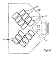
- the piezocrystals 11 are attached to the membrane before they are attached to the piezoceramic plate 10 plate 9 is already separated from the piezoceramic plate (10) except for at least one connecting web 12. The final separation of the piezo crystals 11 then takes place after the piezoceramic plate 10 has been fastened to the membrane plate 9 by severing the connecting webs by means of a separating device.
- the base body 1, the membrane plate 9 and the piezoceramic plate 10 partially have the same outer contour, such that they can be mounted flush and connected to one another. This has the advantage that a separate positioning of the individual crystals is no longer necessary.
- the plate-shaped base body 11 and the membrane plate 9 z. B. firmly connected to each other by means of an adhesive connection.
- the membrane plate 9 was still covered with an electrically conductive layer, e.g. B. provided a nickel oxide layer 13.
- the piezoceramic plate 10 already provided with laser cuts is also firmly connected to the membrane plate 9 by means of an adhesive connection.
- the connecting webs 12 are then severed in the parting lines by means of a laser beam device, as a result of which the piezo crystals 11 arranged above each pressure chamber 3 are separated from the piezoceramic plate 10 and thus vibrate freely. All piezocrystals 11 of the inkjet print head 2 are thus assembled as an assembly part and glued to the membrane plate 9. Good adhesive dosing is ensured by means of a squeegee, screen printing or a spin process. The assembly method according to the invention also ensures the flatness of the piezo crystals 11 to the membrane plate 9 required for the same operating voltages.
- the pressure chambers 3 and the ink channels 6, 7 and the ink supply chamber 5 are e.g. B. incorporated into the base body 1 by an etching process.
- the membrane plate 9 designed as a glass face plate can also be connected to the base body by a sintering process.
Landscapes
- Particle Formation And Scattering Control In Inkjet Printers (AREA)
Applications Claiming Priority (2)
| Application Number | Priority Date | Filing Date | Title |
|---|---|---|---|
| DE3804165 | 1988-02-11 | ||
| DE3804165A DE3804165A1 (de) | 1988-02-11 | 1988-02-11 | Verfahren zum bestuecken eines tintenstrahldruckkopfes mit piezokristallen |
Publications (2)
| Publication Number | Publication Date |
|---|---|
| EP0327802A2 true EP0327802A2 (fr) | 1989-08-16 |
| EP0327802A3 EP0327802A3 (fr) | 1990-01-31 |
Family
ID=6347144
Family Applications (1)
| Application Number | Title | Priority Date | Filing Date |
|---|---|---|---|
| EP89100188A Withdrawn EP0327802A3 (fr) | 1988-02-11 | 1989-01-07 | Méthode pour équiper une tête à jet d'encre avec des cristaux piézo-électriques d'impression |
Country Status (4)
| Country | Link |
|---|---|
| US (1) | US4897903A (fr) |
| EP (1) | EP0327802A3 (fr) |
| JP (1) | JPH024518A (fr) |
| DE (1) | DE3804165A1 (fr) |
Cited By (1)
| Publication number | Priority date | Publication date | Assignee | Title |
|---|---|---|---|---|
| FR2713144A1 (fr) * | 1993-11-30 | 1995-06-09 | Rohm Co Ltd | Tête d'impression à jets d'encre et imprimante la comportant. |
Families Citing this family (13)
| Publication number | Priority date | Publication date | Assignee | Title |
|---|---|---|---|---|
| JPH0714797B2 (ja) * | 1990-11-30 | 1995-02-22 | 株式会社キトー | 電動チェーンブロック |
| DE4225799A1 (de) * | 1992-07-31 | 1994-02-03 | Francotyp Postalia Gmbh | Tintenstrahldruckkopf und Verfahren zu seiner Herstellung |
| US5825382A (en) * | 1992-07-31 | 1998-10-20 | Francotyp-Postalia Ag & Co. | Edge-shooter ink jet print head and method for its manufacture |
| US6050679A (en) * | 1992-08-27 | 2000-04-18 | Hitachi Koki Imaging Solutions, Inc. | Ink jet printer transducer array with stacked or single flat plate element |
| DE59509149D1 (de) * | 1994-08-03 | 2001-05-10 | Francotyp Postalia Gmbh | Anordnung für plattenförmige Piezoaktoren und Verfahren zu deren Herstellung |
| GB9808182D0 (en) * | 1998-04-17 | 1998-06-17 | The Technology Partnership Plc | Liquid projection apparatus |
| DE19931110A1 (de) * | 1999-07-06 | 2001-01-25 | Ekra Eduard Kraft Gmbh | Druckkopf zum Ausspritzen eines heißen flüssigen Mediums und Verfahren zur Herstellung einer metallisches Lot umfassenden Verbindungsstelle |
| US6464324B1 (en) | 2000-01-31 | 2002-10-15 | Picojet, Inc. | Microfluid device and ultrasonic bonding process |
| US20060050109A1 (en) * | 2000-01-31 | 2006-03-09 | Le Hue P | Low bonding temperature and pressure ultrasonic bonding process for making a microfluid device |
| USD514618S1 (en) | 2002-09-12 | 2006-02-07 | Seiko Epson Corporation | Ink jet liquid injector |
| US7862678B2 (en) | 2006-04-05 | 2011-01-04 | Xerox Corporation | Drop generator |
| WO2010036235A1 (fr) * | 2008-09-23 | 2010-04-01 | Hewlett-Packard Development Company, L.P. | Suppression de matériau piézoélectrique à l’aide d’un rayonnement électromagnétique |
| US9139004B2 (en) * | 2012-03-05 | 2015-09-22 | Xerox Corporation | Print head transducer dicing directly on diaphragm |
Family Cites Families (11)
| Publication number | Priority date | Publication date | Assignee | Title |
|---|---|---|---|---|
| SE349676B (fr) * | 1971-01-11 | 1972-10-02 | N Stemme | |
| DE2256667C3 (de) * | 1972-11-18 | 1975-04-30 | Olympia Werke Ag, 2940 Wilhelmshaven | Vorrichtung zum Erzeugen von Druckimpulsen, die in einem Grundkörper angeordnet sind |
| DE3234408C2 (de) * | 1982-09-16 | 1986-01-09 | Siemens AG, 1000 Berlin und 8000 München | Schreibkopf mit piezoelektrischen Antriebselementen für Tintenschreibeinrichtungen |
| DE3342844A1 (de) * | 1983-11-26 | 1985-06-05 | Philips Patentverwaltung Gmbh, 2000 Hamburg | Mikroplanarer tintenstrahldruckkopf |
| DE3412531A1 (de) * | 1984-04-04 | 1985-10-17 | Olympia Werke Ag, 2940 Wilhelmshaven | Tintendruckeinrichtung zum mehrfarbigen bedrucken eines aufzeichnungstraegers |
| US4605939A (en) * | 1985-08-30 | 1986-08-12 | Pitney Bowes Inc. | Ink jet array |
| US4641153A (en) * | 1985-09-03 | 1987-02-03 | Pitney Bowes Inc. | Notched piezo-electric transducer for an ink jet device |
| US4668964A (en) * | 1985-11-04 | 1987-05-26 | Ricoh Company, Ltd. | Stimulator for inkjet printer |
| DE3608205A1 (de) * | 1986-03-12 | 1987-09-17 | Olympia Ag | Piezoelektrisch betriebener schreibkopf fuer tintenmosaikschreibeinrichtungen |
| US4751774A (en) * | 1986-08-29 | 1988-06-21 | Dataproducts Corporation | Method of fabricating an ink jet apparatus |
| US4768266A (en) * | 1986-08-29 | 1988-09-06 | Dataproducts Corporation | Method of making an ink jet printer transducer array |
-
1988
- 1988-02-11 DE DE3804165A patent/DE3804165A1/de not_active Withdrawn
-
1989
- 1989-01-07 EP EP89100188A patent/EP0327802A3/fr not_active Withdrawn
- 1989-01-30 JP JP1017810A patent/JPH024518A/ja active Pending
- 1989-02-10 US US07/309,082 patent/US4897903A/en not_active Expired - Fee Related
Cited By (1)
| Publication number | Priority date | Publication date | Assignee | Title |
|---|---|---|---|---|
| FR2713144A1 (fr) * | 1993-11-30 | 1995-06-09 | Rohm Co Ltd | Tête d'impression à jets d'encre et imprimante la comportant. |
Also Published As
| Publication number | Publication date |
|---|---|
| JPH024518A (ja) | 1990-01-09 |
| EP0327802A3 (fr) | 1990-01-31 |
| US4897903A (en) | 1990-02-06 |
| DE3804165A1 (de) | 1989-08-24 |
Similar Documents
| Publication | Publication Date | Title |
|---|---|---|
| DE69133469T2 (de) | Auf Abruf arbeitender Tintenstrahldruckkopf | |
| DE69232548T2 (de) | Auf Anforderung arbeitender Tintenstrahldruckkopf | |
| DE69302226T2 (de) | Tintenstrahlaufzeichnungskopf | |
| EP0327802A2 (fr) | Méthode pour équiper une tête à jet d'encre avec des cristaux piézo-électriques d'impression | |
| EP0268204B1 (fr) | Pompe piézo-électrique | |
| DE69414192T2 (de) | Tintenstrahlaufzeichnungsgerät mit elektrostatischem Betätiger und Verfahren zu seinem Betrieb | |
| DE69515708T2 (de) | Tintenstrahlaufzeichnungsgerät | |
| DE68907434T2 (de) | Tintenstrahlkopf. | |
| DE69716157T2 (de) | Piezolelektrischer Vibrator, diesen piezoelektrischen Vibrator verwendender Tintenstrahldruckkopf und Verfahren zur Herstellung | |
| EP0615845A2 (fr) | Méthode pour la fabrication d'une tête d'impression par jet d'encre piézoélectrique ayant la largeur d'une page | |
| DE10230117B4 (de) | Piezoelektrisches Mehrschichtbauelement und Verfahren zum Herstellen desselben und Verwendung desselben in einem piezoelektrischen Betätigungsglied | |
| DE2256667C3 (de) | Vorrichtung zum Erzeugen von Druckimpulsen, die in einem Grundkörper angeordnet sind | |
| DE69931001T2 (de) | Piezoelektrischer Vibrator, Verfahren zu dessen Herstellung und diesen piezoelektrischen Vibrator verwendender Tintenstrahldruckkopf | |
| EP0648607A2 (fr) | Plaque de tuyères d'une tête à jet d'encre et procédé pour sa fabrication | |
| DE69535609T2 (de) | Farbstrahldruckkopfherstellungsverfahren | |
| EP0150348A2 (fr) | Tête d'impression à jet d'encre | |
| DE69422090T3 (de) | Tintenstrahlaufzeichnungskopf | |
| EP0307403B1 (fr) | Tete d'ecriture a l'encre avec membrane a excitation piezoelectrique | |
| DE3126351C2 (de) | Gerät zur Bildung eines Tröpfchenstrahles | |
| DE4435914A1 (de) | Piezoelektrischer Antrieb für einen Tintenstrahldruckkopf und Verfahren zu dessen Herstellung | |
| DE69307576T2 (de) | Piezoelektrische Vorrichtung zur Erzeugung eines Flüssigkeitsstrahles | |
| EP0713775B1 (fr) | Agencement pour une tête d'impression à jet d'encre modulaire | |
| EP0057956A2 (fr) | Tête à écrire pour une imprimante à jet d'encre | |
| DE19941189A1 (de) | Tintenstrahl-Schreibkopf | |
| DE10026133B4 (de) | Verfahren zum Herstellen eines Tintenstrahldruckkopfs |
Legal Events
| Date | Code | Title | Description |
|---|---|---|---|
| PUAI | Public reference made under article 153(3) epc to a published international application that has entered the european phase |
Free format text: ORIGINAL CODE: 0009012 |
|
| AK | Designated contracting states |
Kind code of ref document: A2 Designated state(s): CH DE FR GB IT LI |
|
| RAP1 | Party data changed (applicant data changed or rights of an application transferred) |
Owner name: AEG OLYMPIA OFFICE GMBH |
|
| PUAL | Search report despatched |
Free format text: ORIGINAL CODE: 0009013 |
|
| AK | Designated contracting states |
Kind code of ref document: A3 Designated state(s): CH DE FR GB IT LI |
|
| 17P | Request for examination filed |
Effective date: 19900716 |
|
| 17Q | First examination report despatched |
Effective date: 19920408 |
|
| STAA | Information on the status of an ep patent application or granted ep patent |
Free format text: STATUS: THE APPLICATION HAS BEEN WITHDRAWN |
|
| 18W | Application withdrawn |
Withdrawal date: 19920703 |