EP0327809A2 - Portable protecting housing for electric and electronic apparatuses - Google Patents
Portable protecting housing for electric and electronic apparatuses Download PDFInfo
- Publication number
- EP0327809A2 EP0327809A2 EP89100287A EP89100287A EP0327809A2 EP 0327809 A2 EP0327809 A2 EP 0327809A2 EP 89100287 A EP89100287 A EP 89100287A EP 89100287 A EP89100287 A EP 89100287A EP 0327809 A2 EP0327809 A2 EP 0327809A2
- Authority
- EP
- European Patent Office
- Prior art keywords
- shield
- jacket
- receiving frame
- edge
- protective housing
- Prior art date
- Legal status (The legal status is an assumption and is not a legal conclusion. Google has not performed a legal analysis and makes no representation as to the accuracy of the status listed.)
- Withdrawn
Links
Images

Classifications
-
- G—PHYSICS
- G12—INSTRUMENT DETAILS
- G12B—CONSTRUCTIONAL DETAILS OF INSTRUMENTS, OR COMPARABLE DETAILS OF OTHER APPARATUS, NOT OTHERWISE PROVIDED FOR
- G12B9/00—Housing or supporting of instruments or other apparatus
-
- H—ELECTRICITY
- H05—ELECTRIC TECHNIQUES NOT OTHERWISE PROVIDED FOR
- H05K—PRINTED CIRCUITS; CASINGS OR CONSTRUCTIONAL DETAILS OF ELECTRIC APPARATUS; MANUFACTURE OF ASSEMBLAGES OF ELECTRICAL COMPONENTS
- H05K5/00—Casings, cabinets or drawers for electric apparatus
- H05K5/0086—Casings, cabinets or drawers for electric apparatus portable, e.g. battery operated apparatus
Definitions
- the present invention relates to a portable protective housing for electrical and electronic devices. It is known that such devices, if they have to be used, for example, for military, research or similar purposes in the case of extreme mechanical and / or climatic stress, are accommodated in vibration-resistant box-shaped housings.
- these protective housings have a self-supporting, box-shaped metallic housing jacket with a front opening that can be closed by a metal cover, in which housing jacket a metal mounting frame suspended from vibration dampers for the device that can be inserted and removed through the jacket front opening is arranged, with an edge profile of the jacket on the one hand and an edge profile of the mounting frame on the other hand each carries a sealing ring.
- the front opening of the housing jacket forms a perfect electrical shield by means of the lid (Faraday cage), but when the lid is removed, i. that is, when the device is accessible for use, the jacket interior is no longer shielded, so that undesired electrical or electromagnetic radiation and / or radiation can occur.
- this problem is solved in that the edge profile, which carries the first sealing ring surrounding the front opening of the housing jacket, and the edge profile, which carries the second sealing ring surrounding the device insertion opening of the receiving frame, by means of a swinging movement that spans the front gap between the housing jacket and receiving frame and oscillating movements of the Receiving frame are electrically connected to one another by means of corresponding metallic or other conductive shields which permit deformation.
- the protective housing shown has a box-shaped, self-supporting metal casing 1 with a front cover 3 which can be fixed to the casing by means of recessed grip bolts 2.
- An edge profile 4 of the casing 1 is provided on the front side with a circumferential groove which is delimited on the inside by a projecting flange 4a.
- On the edge profile 4 are also not shown engaging plates 8 for the handle bolts 2 attached, which lead through angled to an edge profile 6 of the lid 3 7.
- a metallic mounting frame 10 is suspended in the metal jacket 1 and at a distance from the wall by means of eight vibration dampers 9.
- the receiving frame 10 standardized with respect to the receiving space, can be fitted with the respective built-in devices from its front side, which is set back relative to the open side of the casing 1.
- edge profile 11 which has a groove on the long sides which is delimited inward by a projecting flange 11a; the narrow sides of the edge profile 11 forming a flange 12, on the other hand, are provided with a series of holes 12a.
- a threaded strip 13 is fastened by means of screws 13b Align threaded bores 13a with the holes 12a of the narrow side flange 12.
- a sealing ring 14 is fitted into the circumferential groove of the edge profile 4 of the housing shell 1, which has a rectangular cross section.
- a corresponding sealing ring 16 is inserted into the likewise circumferential groove of the edge profile 11 of the receiving frame 10.
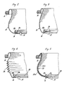
- the space between the two edge profiles 4 and 10 is spanned by a metallic shield 15, which is formed by a fabric or a close-meshed network.
- This shield 15 is connected to the sealing rings 14, 16 in the corresponding groove under the edge parts through these firmly pressed sealing rings with the edge profiles 4 and 10 and thus with the housing jacket 1 and the receiving frame 10 in an electrically conductive manner.
- the shield 15 closes the gap between the housing jacket 1 and the receiving frame 10 from the outside without any problems.
- the desired device (not shown) can be inserted into the receiving frame 10 and fixed on all sides by means of screws on the threaded strip 13 using the protruding edge of its front plate corresponding to the standardization of the receiving frame.
- the device is thus not only electrically shielded and vibration-proof housed in the housing casing 1 when the cover 3 is in place, but also with the cover removed, that is to say in the operating state, perfectly protected against electromagnetic radiation and radiation thanks to the shielding 15.
- the edges of the shield 15, which is designed as a rectangular tube, can be fitted with e.g. rubber sealing rings 14 and 16 are connected. If the shield 15 is not itself sufficient as a seal against moisture and dust, it can be coated on one or both sides with a suitable sealing material, e.g. Be plastic or rubber coated, if care is taken to ensure that the electrically conductive connection of the shield to the edge profiles 4 and 11 is retained.
- a suitable sealing material e.g. Be plastic or rubber coated
- the shield 15 was assumed to be formed by a metal wire mesh or net which, owing to its easy deformability on all sides, is particularly well suited for permitting oscillating movements of the receiving frame
- the shield could also be, as shown at 25 in FIG. 4 a metal foil may be formed. This can be provided with a zigzag-like fold in order to create the necessary excess length in relation to the distance between the two edge profiles 4 and 11 and for stiffening to prevent undesired denting.
- FIG. 5 Another variant is shown in FIG. 5.
- the sealing rings 14 and 16 form a unit with the metallic shield 35a.
- the shield 35a is embedded in a sealing bellows 35b which integrally connects the two sealing rings 14, 16, the end portions of the shield 35a being led out of the two sealing rings 14, 16 and, when the sealing unit 14, 35b, 16 is inserted, the electrical connection of the shield to ensure the edge profiles 4, 11.
- the shield 35a can be formed by a mesh or a woven fabric made of metal wire or by a metal foil.
- the metallic shield expediently consists of an electrically highly conductive material, e.g. Aluminum, copper or a corresponding alloy. In certain cases, however, a steel shield or a shield consisting of a non-metallic carrier material provided with a galvanic coating can also be provided.
- the electrically conductive shield always connects the two sealing rings 14 and 16 to one another and is kept in conductive connection with the metallic edge profiles
- the end portions of the shield could also be connected to the edge profiles 4 and / or independently of one or both sealing rings 11 be electrically connected. It is only essential that, even when the cover is removed, it spans the space between the two marginal profiles so that a flawless electrical or electromagnetic is formed by forming a Faraday cage Shielding is guaranteed and at the same time allows swinging movements of the receiving frame unhindered without being exposed to undesirable mechanical loads.
Landscapes
- Engineering & Computer Science (AREA)
- Microelectronics & Electronic Packaging (AREA)
- Shielding Devices Or Components To Electric Or Magnetic Fields (AREA)
- Casings For Electric Apparatus (AREA)
Abstract
Description
Gegenstand der vorliegenden Erfindung ist ein tragbares Schutzgehäuse für elektrische und elektronische Geräte. Es ist bekannt, solche Geräte, wenn sie z.B. für militärische, Forschungs oder ähnliche Zwecke bei extremer mechanischer und/oder klimatischer Beanspruchung eingesetzt werden müssen in vibrationsfesten kastenförmigen Gehäusen unterzubringen. Ueblicherweise besitzen diese Schutzgehäuse einen selbsttragenden, kastenförmigen metallischen Gehäusemantel mit durch einen Metalldeckel abschliessbarer Frontöffnung, in welchen Gehäusemantel ein an Schwingungsdämpfern aufgehängter metallischer Aufnahmerahmen für das durch die Mantelfrontöffnung ein- und ausbaubare Gerät angeordnet ist, wobei ein Randprofil des Mantels einerseits und ein Randprofil des Aufnahmerahmens anderseits je einen Dichtungsring trägt.The present invention relates to a portable protective housing for electrical and electronic devices. It is known that such devices, if they have to be used, for example, for military, research or similar purposes in the case of extreme mechanical and / or climatic stress, are accommodated in vibration-resistant box-shaped housings. Usually, these protective housings have a self-supporting, box-shaped metallic housing jacket with a front opening that can be closed by a metal cover, in which housing jacket a metal mounting frame suspended from vibration dampers for the device that can be inserted and removed through the jacket front opening is arranged, with an edge profile of the jacket on the one hand and an edge profile of the mounting frame on the other hand each carries a sealing ring.
In vielen Fällen hat es sich als nachteilig erwiesen, dass zwar die Frontöffnung des Gehäusemantels mittels des Deckels eine einwandfreie elektrische Abschirmung bildet (Faradayscher Käfig), bei abgenommenem Deckel aber, d.h. also bei zur Benützung zugänglichem Gerät, der Mantelinnenraum nicht mehr abgeschirmt ist, sodass unerwünschte elektrische bzw. elektromagnetische Ein- und/oder Ausstrahlungen erfolgen können.In many cases, it has proven to be disadvantageous that the front opening of the housing jacket forms a perfect electrical shield by means of the lid (Faraday cage), but when the lid is removed, i. that is, when the device is accessible for use, the jacket interior is no longer shielded, so that undesired electrical or electromagnetic radiation and / or radiation can occur.
Erfindungsgemäss wird dieses Problem dadurch gelöst, dass das Randprofil, das den die Frontöffnung des Gehäusemantels umschliessenden ersten Dichtungsring trägt, und das Randprofil, das den die Geräteeinschuböffnung des Aufnahmerahmens umschliessenden zweiten Dichtungsring trägt, durch eine den Frontspalt zwischen Gehäusemantel- und Aufnahmerahmen überspannende und Schwingbewegungen des Aufnahmerahmens durch entsprechende Deformation zulassende metallische oder andere leitende Abschirmung miteinander elektrisch verbunden sind.According to the invention, this problem is solved in that the edge profile, which carries the first sealing ring surrounding the front opening of the housing jacket, and the edge profile, which carries the second sealing ring surrounding the device insertion opening of the receiving frame, by means of a swinging movement that spans the front gap between the housing jacket and receiving frame and oscillating movements of the Receiving frame are electrically connected to one another by means of corresponding metallic or other conductive shields which permit deformation.
Damit ist auch bei abgenommenem Deckel der Zwischenraum zwischen Mantel und Rahmen gegen unerwünschte elektrische bzw. elektromagnetische Ein- bzw. Ausstrahlungen abgeschlossen. Besonders vorteilhafte Ausführungsformen der Erfindung sind in den Ansprüchen 2 bis 5 aufgeführt.Thus, even with the cover removed, the space between the casing and the frame is closed against undesired electrical or electromagnetic radiation. Particularly advantageous embodiments of the invention are set out in claims 2 to 5.
Anhand der beiliegenden Zeichnung ist die Erfindung im folgenden beispielsweise näher erläutert. In der Zeichnung zeigt
- Fig. 1 einen Querschnitt durch einen Teil der Frontpartie des Gehäuses bei abgehobenem Deckel (ohne das einzusetzende Gerät),
- Fig. 2 und 3 einen Querschnitt durch eine Längsseite bzw. eine Schmalseite der im Grundriss rechteckförmigen Abschirmung gemäss Fig. 1 mit zugeordneten Dichtungsringen vor deren Einsatz in das Traggehäuse
- Fig. 4 und 5 einen Querschnitt durch eine Längsseite je einer Variante der Abschirmung nach Fig. 2.
- 1 shows a cross section through part of the front part of the housing when the cover is lifted off (without the device to be used),
- 2 and 3 a cross section through a long side or a narrow side of the shielding rectangular in plan according to FIG. 1 with associated sealing rings before their use in the support housing
- 4 and 5 a cross section through a longitudinal side of each variant of the shield according to FIG. 2nd
Das gezeichnete Schutzgehäuse besitzt einen kastenförmigen, selbsttragenden Metallmantel 1 mit mittels versenkter Griffbolzen 2 am Mantel fixierbarem Frontdeckel 3. Ein Randprofil 4 des Mantels 1 ist frontseitig mit einer Umfangsnut versehen, die nach innen von einem überstehenden Flansch 4a begrenzt ist. Am Randprofil 4 sind ferner nicht gezeichnete Eingriffsplatten 8 für die Griffbolzen 2 befestigt, die durch an einem Randprofil 6 des Deckels 3 befestigte Winkelplatten 7 hindurchführen. Im Metallmantel 1 und im Wandabstand zu diesem ist mittels acht Schwingungsdämpfern 9 ein metallischer Aufnahmerahmen 10 aufgehängt. Der bezüglich Aufnahmeraum genormte Aufnahmerahmen 10 ist von seiner gegenüber der Offenseite des Mantels 1 zurückversetzten Frontseite her mit den jeweiligen Einbaugeräten bestückbar. Er besitzt ein Randprofil 11, das an den Längsseiten eine Nut aufweist, die nach innen von einem überstehenden Flansch 11a begrenzt ist; die einen Flansch 12 bildenden Schmalseiten des Randprofils 11 dagegen sind mit einer Reihe von Löchern 12a versehen. An der Unterseite des Schmalseitenflansches 12 des Randprofils 11 ist mittels Schrauben 13b eine Gewindeleiste 13 befestigt, deren Gewindebohrungen 13a mit den Löchern 12a des Schmalseitenflansches 12 fluchten.The protective housing shown has a box-shaped, self-supporting metal casing 1 with a
In die Rechteckquerschnitt aufweisende, umlaufende Nut des Randprofils 4 des Gehäusemantels 1 ist ein Dichtungsring 14 eingepasst. Ein entsprechender Dichtungsring 16 ist in die ebenfalls umlaufende Nut des Randprofils 11 des Aufnahmerahmens 10 eingesetzt. Der Zwischenraum zwischen den beiden Randprofilen 4 und 10 ist von einer metallischen Abschirmung 15 überspannt, die durch ein Gewebe oder ein engmaschiges Netz gebildet ist. Diese Abschirmung 15 ist mit ihren die Dichtungsringe 14, 16 in der entsprechenden Nut untergreifenden Randpartien durch diese fest eingepressten Dichtungsringe mit den Randprofilen 4 und 10 und damit mit dem Gehäusemantel 1 und dem Aufnahmerahmen 10 elektrisch leitend verbunden.A
Wie aus Fig. 1 ersichtlich, schliesst die Abschirmung 15 den Spaltraum zwischen Gehäusemantel 1 und Aufnahmerahmen 10 einwandfrei nach aussen ab. Nun kann wie üblich das gewünschte Gerät (nicht gezeichnet) in den Aufnahmerahmen 10 eingeschoben und mit dem überstehenden Rand seiner der Normung des Aufnahmerahmens entsprechenden Frontplatte auf dem Dichtungring 15 allseitig aufliegend mittels Schrauben an der Gewindeleiste 13 fixiert werden. Damit ist nicht nur der Spaltraum zwischen Mantel und Aufnahmerahmen, sondern auch die Einschuböffnung des Aufnahmerahmens 10 und somit das eingebaute Gerät einwandfrei elektrisch abgeschirmt. Die dank der Ueberlänge (Fig. 2 und 3) ausgebauchte Abschirmung behindert in keiner Weise die infolge der schwingungsdämpfenden Aufhängung des Aufnahmerahmens 10 etwa auftretenden Relativbewegungen von Gehäusemantel 1 und Aufnahmerahmen 10, da diese stets relativ kleinen Bewegungen die Abschirmung an keiner Stelle zu strecken bzw. unzulässig zu dehnen vermögen. Das Gerät ist somit nicht nur bei aufgesetztem Deckel 3 elektrisch abgeschirmt und vibrationsfest im Gehäusemantel 1 untergebracht, sondern auch bei abgenommenem Deckel, d.h. im Betriebszustand, dank der Abschirmung 15 gegen elektromagnetische Ein- und Ausstrahlungen einwandfrei geschützt.As can be seen from FIG. 1, the
Wie die Fig. 2 und 3 zeigen, können die Ränder der als Rechteckschlauch ausgebildeten Abschirmung 15 schon vor deren Einbau mit den z.B. aus Gummi bestehenden Dichtungsringen 14 und 16 verbunden werden. Sofern die Abschirmung 15 nicht selbst schon als Dichtung gegen Feuchtigkeit und Staub genügt, kann sie ein- oder beidseitig mit einem geeigneten Dichtungsmaterial z.B. Kunststoff oder Gummi beschichtet sein, sofern darauf geachtet wird, dass die elektrisch leitende Verbindung der Abschirmung mit den Randprofilen 4 und 11 erhalten bleibt.As shown in FIGS. 2 and 3, the edges of the
Während beim vorangehend beschriebenen Beispiel die Abschirmung 15 als durch ein Metalldrahtgewebe oder Netz gebildet angenommen wurde, das sich dank seiner allseitigen leichten Verformbarkeit zur Zulassung von Schwingbewegungen des Aufnahmerahmens besonders gut eignet, könnte die Abschirmung, wie bei 25 in Fig. 4 gezeigt, auch durch eine Metallfolie gebildet sein. Diese kann zur Schaffung der notwendigen Ueberlänge gegenüber dem Abstand der beiden Randprofile 4 und 11 und zur ein unerwünschtes Einbeulen verhindernden Versteifung mit einer zickzackartigen Faltung versehen sein.While, in the example described above, the
Eine weitere Variante ist in Fig. 5 dargestellt. Hier bilden die Dichtungsringe 14 und 16 mit der metallischen Abschirmung 35a eine Einheit. Die Abschirmung 35a liegt dabei eingebettet in einem die beiden Dichtungsringe 14, 16 einstückig miteinander verbindenden Dichtungsbalg 35b, wobei die Endpartien der Abschirmung 35a aus den beiden Dichtungsringen 14, 16 herausgeführt sind und bei eingesetzter Dichtungseinheit 14, 35b, 16 die elektrische Verbindung der Abschirmung mit den Randprofilen 4, 11 gewährleisten. Es versteht sich, dass auch in diesem Fall die Abschirmung 35a durch ein Netz oder ein Gewebe aus Metalldraht oder durch eine Metallfolie gebildet sein kann.Another variant is shown in FIG. 5. Here the
Zweckmässig besteht die metallische Abschirmung aus einem elektrisch gut leitenden Material wie z.B. Aluminium, Kupfer oder einer entsprechenden Legierung. Es kann in gewissen Fällen aber auch eine Stahlabschirmung oder eine aus einem nicht metallischen, mit einem galvanischen Ueberzug versehenen Trägermaterial bestehende Abschirmung vorgesehen sein.The metallic shield expediently consists of an electrically highly conductive material, e.g. Aluminum, copper or a corresponding alloy. In certain cases, however, a steel shield or a shield consisting of a non-metallic carrier material provided with a galvanic coating can also be provided.
Während bei den vorangehend beschriebenen Ausführungsformen die elektrisch leitende Abschirmung stets die beiden Dichtungsringe 14 und 16 miteinander verbindet und durch diese in leitender Verbindung mit den metallischen Randprofilen gehalten ist, könnten die Endpartien der Abschirmung auch unabhängig vom einen oder beiden Dichtungsringen direkt mit den Randprofilen 4 bzw. 11 elektrisch leitend verbunden sein. Wesentlich ist nur, dass sie dabei auch bei abgenommenem Deckel den Zwischenraum zwischen den beiden Randprodilen so überspannt, dass durch Bildung eines Faradayschen Käfigs eine einwandfreie elektrische bzw. elektromagnetische Abschirmung gewährleistet ist und gleichzeitig Schwingbewegungen des Aufnahmerahmens ungehindert zulässt ohne dabei selbst unerwünschten mechanischen Belastungen ausgesetzt zu sein.While in the embodiments described above, the electrically conductive shield always connects the two
Claims (5)
Applications Claiming Priority (2)
| Application Number | Priority Date | Filing Date | Title |
|---|---|---|---|
| CH52188A CH675808A5 (en) | 1988-02-12 | 1988-02-12 | |
| CH521/88 | 1988-02-12 |
Publications (2)
| Publication Number | Publication Date |
|---|---|
| EP0327809A2 true EP0327809A2 (en) | 1989-08-16 |
| EP0327809A3 EP0327809A3 (en) | 1990-01-24 |
Family
ID=4188907
Family Applications (1)
| Application Number | Title | Priority Date | Filing Date |
|---|---|---|---|
| EP89100287A Withdrawn EP0327809A3 (en) | 1988-02-12 | 1989-01-10 | Portable protecting housing for electric and electronic apparatuses |
Country Status (2)
| Country | Link |
|---|---|
| EP (1) | EP0327809A3 (en) |
| CH (1) | CH675808A5 (en) |
Cited By (4)
| Publication number | Priority date | Publication date | Assignee | Title |
|---|---|---|---|---|
| DE4221119A1 (en) * | 1992-06-26 | 1994-01-05 | Knuerr Mechanik Ag | Portable HF-screened metal case for protection of electrical equipment - has one-piece external housing with front and rear access reinforced at bevelled peripheries and has hollow front and rear sections and separate vibration-damped interior frame. |
| EP0823834A3 (en) * | 1996-08-05 | 1998-08-05 | Edak Ag | Stacked module |
| EP1708555A1 (en) * | 2005-04-01 | 2006-10-04 | Knürr AG | Suspension device |
| CH709177A1 (en) * | 2014-01-27 | 2015-07-31 | Edak Ag | Support housing for the reception of Electronics. |
Family Cites Families (3)
| Publication number | Priority date | Publication date | Assignee | Title |
|---|---|---|---|---|
| US3350497A (en) * | 1965-08-23 | 1967-10-31 | Craig Systems Corp | Shielded passageway interconnection for radio-frequency shelters |
| US4115656A (en) * | 1976-04-08 | 1978-09-19 | Sanders Associates, Inc. | Shielded passageway interconnection for electromagnetic interference shielded shelters |
| CH650890A5 (en) * | 1981-06-15 | 1985-08-15 | Edak Ag | PORTABLE PROTECTIVE HOUSING FOR ELECTRICAL AND ELECTRONIC DEVICES. |
-
1988
- 1988-02-12 CH CH52188A patent/CH675808A5/de not_active IP Right Cessation
-
1989
- 1989-01-10 EP EP89100287A patent/EP0327809A3/en not_active Withdrawn
Cited By (5)
| Publication number | Priority date | Publication date | Assignee | Title |
|---|---|---|---|---|
| DE4221119A1 (en) * | 1992-06-26 | 1994-01-05 | Knuerr Mechanik Ag | Portable HF-screened metal case for protection of electrical equipment - has one-piece external housing with front and rear access reinforced at bevelled peripheries and has hollow front and rear sections and separate vibration-damped interior frame. |
| EP0823834A3 (en) * | 1996-08-05 | 1998-08-05 | Edak Ag | Stacked module |
| EP1708555A1 (en) * | 2005-04-01 | 2006-10-04 | Knürr AG | Suspension device |
| WO2006102952A3 (en) * | 2005-04-01 | 2006-12-07 | Knuerr Ag | Housing device |
| CH709177A1 (en) * | 2014-01-27 | 2015-07-31 | Edak Ag | Support housing for the reception of Electronics. |
Also Published As
| Publication number | Publication date |
|---|---|
| CH675808A5 (en) | 1990-10-31 |
| EP0327809A3 (en) | 1990-01-24 |
Similar Documents
| Publication | Publication Date | Title |
|---|---|---|
| DE69202405T2 (en) | A circuit board arrangement. | |
| DE4122245A1 (en) | ELECTROMAGNETIC SHIELDING LINK | |
| DE60001573T2 (en) | PROTECTIVE DEVICE AGAINST ELECTROMAGNETIC RADIATION WITH GASKETS | |
| DE19706790C2 (en) | Control unit for installation in a motor vehicle | |
| DE4436303A1 (en) | Electronics and instrumentation housing and frame therefor | |
| EP0068125B1 (en) | Portable protective housing for electrical and electronic apparatuses | |
| DE10111646B4 (en) | Shielded control cabinet housing | |
| EP0327809A2 (en) | Portable protecting housing for electric and electronic apparatuses | |
| DE9218209U1 (en) | Electrical connector | |
| DE3815517A1 (en) | GASKET FOR AN ELECTROMAGNETIC RADIATION SHIELDING HOUSING | |
| DE4436547A1 (en) | Housing for electronic modules mounted on circuit board for insertion in motor vehicles | |
| DE19548723A1 (en) | Housing for receiving electronic components | |
| EP0819369B1 (en) | Filtering device with a filter housing, a filter mat and a lamella grid | |
| DE102020127486A1 (en) | System and method for assembling an electronic assembly | |
| DE19734128C1 (en) | Sealed plastics housing for accommodating printed circuit board e.g. for automobile industry | |
| DE69803593T2 (en) | DEVICE | |
| DE4309084C2 (en) | Radiation-proof housing | |
| DE4221479A1 (en) | Contact assembly maintaining EM screening of room - has brush with metal base and steel or phosphor-bronze wire bristles forming contact between fixed and moving parts | |
| DE19880835B4 (en) | shield | |
| DE102016119293A1 (en) | Electronics, in particular power electronics and system | |
| DE19603368A1 (en) | HF-tight housing for electronic measurement devices | |
| DE112019007684T5 (en) | electrical device | |
| DE4422242C1 (en) | Universal cassette for electrical component group within appts. housing | |
| DE29514573U1 (en) | Control device, in particular for a motor vehicle | |
| DE202024104173U1 (en) | Socket with a hinged cover |
Legal Events
| Date | Code | Title | Description |
|---|---|---|---|
| PUAI | Public reference made under article 153(3) epc to a published international application that has entered the european phase |
Free format text: ORIGINAL CODE: 0009012 |
|
| AK | Designated contracting states |
Kind code of ref document: A2 Designated state(s): DE FR GB IT NL SE |
|
| PUAL | Search report despatched |
Free format text: ORIGINAL CODE: 0009013 |
|
| AK | Designated contracting states |
Kind code of ref document: A3 Designated state(s): DE FR GB IT NL SE |
|
| STAA | Information on the status of an ep patent application or granted ep patent |
Free format text: STATUS: THE APPLICATION HAS BEEN WITHDRAWN |
|
| 18W | Application withdrawn |
Withdrawal date: 19900412 |