EP0327809A2 - Boîtier de protection portatif pour appareils électriques et électroniques - Google Patents
Boîtier de protection portatif pour appareils électriques et électroniques Download PDFInfo
- Publication number
- EP0327809A2 EP0327809A2 EP89100287A EP89100287A EP0327809A2 EP 0327809 A2 EP0327809 A2 EP 0327809A2 EP 89100287 A EP89100287 A EP 89100287A EP 89100287 A EP89100287 A EP 89100287A EP 0327809 A2 EP0327809 A2 EP 0327809A2
- Authority
- EP
- European Patent Office
- Prior art keywords
- shield
- jacket
- receiving frame
- edge
- protective housing
- Prior art date
- Legal status (The legal status is an assumption and is not a legal conclusion. Google has not performed a legal analysis and makes no representation as to the accuracy of the status listed.)
- Withdrawn
Links
Images

Classifications
-
- G—PHYSICS
- G12—INSTRUMENT DETAILS
- G12B—CONSTRUCTIONAL DETAILS OF INSTRUMENTS, OR COMPARABLE DETAILS OF OTHER APPARATUS, NOT OTHERWISE PROVIDED FOR
- G12B9/00—Housing or supporting of instruments or other apparatus
-
- H—ELECTRICITY
- H05—ELECTRIC TECHNIQUES NOT OTHERWISE PROVIDED FOR
- H05K—PRINTED CIRCUITS; CASINGS OR CONSTRUCTIONAL DETAILS OF ELECTRIC APPARATUS; MANUFACTURE OF ASSEMBLAGES OF ELECTRICAL COMPONENTS
- H05K5/00—Casings, cabinets or drawers for electric apparatus
- H05K5/0086—Casings, cabinets or drawers for electric apparatus portable, e.g. battery operated apparatus
Definitions
- the present invention relates to a portable protective housing for electrical and electronic devices. It is known that such devices, if they have to be used, for example, for military, research or similar purposes in the case of extreme mechanical and / or climatic stress, are accommodated in vibration-resistant box-shaped housings.
- these protective housings have a self-supporting, box-shaped metallic housing jacket with a front opening that can be closed by a metal cover, in which housing jacket a metal mounting frame suspended from vibration dampers for the device that can be inserted and removed through the jacket front opening is arranged, with an edge profile of the jacket on the one hand and an edge profile of the mounting frame on the other hand each carries a sealing ring.
- the front opening of the housing jacket forms a perfect electrical shield by means of the lid (Faraday cage), but when the lid is removed, i. that is, when the device is accessible for use, the jacket interior is no longer shielded, so that undesired electrical or electromagnetic radiation and / or radiation can occur.
- this problem is solved in that the edge profile, which carries the first sealing ring surrounding the front opening of the housing jacket, and the edge profile, which carries the second sealing ring surrounding the device insertion opening of the receiving frame, by means of a swinging movement that spans the front gap between the housing jacket and receiving frame and oscillating movements of the Receiving frame are electrically connected to one another by means of corresponding metallic or other conductive shields which permit deformation.
- the protective housing shown has a box-shaped, self-supporting metal casing 1 with a front cover 3 which can be fixed to the casing by means of recessed grip bolts 2.
- An edge profile 4 of the casing 1 is provided on the front side with a circumferential groove which is delimited on the inside by a projecting flange 4a.
- On the edge profile 4 are also not shown engaging plates 8 for the handle bolts 2 attached, which lead through angled to an edge profile 6 of the lid 3 7.
- a metallic mounting frame 10 is suspended in the metal jacket 1 and at a distance from the wall by means of eight vibration dampers 9.
- the receiving frame 10 standardized with respect to the receiving space, can be fitted with the respective built-in devices from its front side, which is set back relative to the open side of the casing 1.
- edge profile 11 which has a groove on the long sides which is delimited inward by a projecting flange 11a; the narrow sides of the edge profile 11 forming a flange 12, on the other hand, are provided with a series of holes 12a.
- a threaded strip 13 is fastened by means of screws 13b Align threaded bores 13a with the holes 12a of the narrow side flange 12.
- a sealing ring 14 is fitted into the circumferential groove of the edge profile 4 of the housing shell 1, which has a rectangular cross section.
- a corresponding sealing ring 16 is inserted into the likewise circumferential groove of the edge profile 11 of the receiving frame 10.
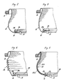
- the space between the two edge profiles 4 and 10 is spanned by a metallic shield 15, which is formed by a fabric or a close-meshed network.
- This shield 15 is connected to the sealing rings 14, 16 in the corresponding groove under the edge parts through these firmly pressed sealing rings with the edge profiles 4 and 10 and thus with the housing jacket 1 and the receiving frame 10 in an electrically conductive manner.
- the shield 15 closes the gap between the housing jacket 1 and the receiving frame 10 from the outside without any problems.
- the desired device (not shown) can be inserted into the receiving frame 10 and fixed on all sides by means of screws on the threaded strip 13 using the protruding edge of its front plate corresponding to the standardization of the receiving frame.
- the device is thus not only electrically shielded and vibration-proof housed in the housing casing 1 when the cover 3 is in place, but also with the cover removed, that is to say in the operating state, perfectly protected against electromagnetic radiation and radiation thanks to the shielding 15.
- the edges of the shield 15, which is designed as a rectangular tube, can be fitted with e.g. rubber sealing rings 14 and 16 are connected. If the shield 15 is not itself sufficient as a seal against moisture and dust, it can be coated on one or both sides with a suitable sealing material, e.g. Be plastic or rubber coated, if care is taken to ensure that the electrically conductive connection of the shield to the edge profiles 4 and 11 is retained.
- a suitable sealing material e.g. Be plastic or rubber coated
- the shield 15 was assumed to be formed by a metal wire mesh or net which, owing to its easy deformability on all sides, is particularly well suited for permitting oscillating movements of the receiving frame
- the shield could also be, as shown at 25 in FIG. 4 a metal foil may be formed. This can be provided with a zigzag-like fold in order to create the necessary excess length in relation to the distance between the two edge profiles 4 and 11 and for stiffening to prevent undesired denting.
- FIG. 5 Another variant is shown in FIG. 5.
- the sealing rings 14 and 16 form a unit with the metallic shield 35a.
- the shield 35a is embedded in a sealing bellows 35b which integrally connects the two sealing rings 14, 16, the end portions of the shield 35a being led out of the two sealing rings 14, 16 and, when the sealing unit 14, 35b, 16 is inserted, the electrical connection of the shield to ensure the edge profiles 4, 11.
- the shield 35a can be formed by a mesh or a woven fabric made of metal wire or by a metal foil.
- the metallic shield expediently consists of an electrically highly conductive material, e.g. Aluminum, copper or a corresponding alloy. In certain cases, however, a steel shield or a shield consisting of a non-metallic carrier material provided with a galvanic coating can also be provided.
- the electrically conductive shield always connects the two sealing rings 14 and 16 to one another and is kept in conductive connection with the metallic edge profiles
- the end portions of the shield could also be connected to the edge profiles 4 and / or independently of one or both sealing rings 11 be electrically connected. It is only essential that, even when the cover is removed, it spans the space between the two marginal profiles so that a flawless electrical or electromagnetic is formed by forming a Faraday cage Shielding is guaranteed and at the same time allows swinging movements of the receiving frame unhindered without being exposed to undesirable mechanical loads.
Landscapes
- Engineering & Computer Science (AREA)
- Microelectronics & Electronic Packaging (AREA)
- Shielding Devices Or Components To Electric Or Magnetic Fields (AREA)
- Casings For Electric Apparatus (AREA)
Applications Claiming Priority (2)
| Application Number | Priority Date | Filing Date | Title |
|---|---|---|---|
| CH52188A CH675808A5 (fr) | 1988-02-12 | 1988-02-12 | |
| CH521/88 | 1988-02-12 |
Publications (2)
| Publication Number | Publication Date |
|---|---|
| EP0327809A2 true EP0327809A2 (fr) | 1989-08-16 |
| EP0327809A3 EP0327809A3 (fr) | 1990-01-24 |
Family
ID=4188907
Family Applications (1)
| Application Number | Title | Priority Date | Filing Date |
|---|---|---|---|
| EP89100287A Withdrawn EP0327809A3 (fr) | 1988-02-12 | 1989-01-10 | Boítier de protection portatif pour appareils électriques et électroniques |
Country Status (2)
| Country | Link |
|---|---|
| EP (1) | EP0327809A3 (fr) |
| CH (1) | CH675808A5 (fr) |
Cited By (4)
| Publication number | Priority date | Publication date | Assignee | Title |
|---|---|---|---|---|
| DE4221119A1 (de) * | 1992-06-26 | 1994-01-05 | Knuerr Mechanik Ag | Gerätekoffer |
| EP0823834A3 (fr) * | 1996-08-05 | 1998-08-05 | Edak Ag | Module empilé |
| EP1708555A1 (fr) * | 2005-04-01 | 2006-10-04 | Knürr AG | Dispositif de suspension |
| CH709177A1 (de) * | 2014-01-27 | 2015-07-31 | Edak Ag | Traggehäuse für die Aufnahme von Elektronik. |
Family Cites Families (3)
| Publication number | Priority date | Publication date | Assignee | Title |
|---|---|---|---|---|
| US3350497A (en) * | 1965-08-23 | 1967-10-31 | Craig Systems Corp | Shielded passageway interconnection for radio-frequency shelters |
| US4115656A (en) * | 1976-04-08 | 1978-09-19 | Sanders Associates, Inc. | Shielded passageway interconnection for electromagnetic interference shielded shelters |
| CH650890A5 (de) * | 1981-06-15 | 1985-08-15 | Edak Ag | Tragbares schutzgehaeuse fuer elektrische und elektronische geraete. |
-
1988
- 1988-02-12 CH CH52188A patent/CH675808A5/de not_active IP Right Cessation
-
1989
- 1989-01-10 EP EP89100287A patent/EP0327809A3/fr not_active Withdrawn
Cited By (5)
| Publication number | Priority date | Publication date | Assignee | Title |
|---|---|---|---|---|
| DE4221119A1 (de) * | 1992-06-26 | 1994-01-05 | Knuerr Mechanik Ag | Gerätekoffer |
| EP0823834A3 (fr) * | 1996-08-05 | 1998-08-05 | Edak Ag | Module empilé |
| EP1708555A1 (fr) * | 2005-04-01 | 2006-10-04 | Knürr AG | Dispositif de suspension |
| WO2006102952A3 (fr) * | 2005-04-01 | 2006-12-07 | Knuerr Ag | Dispositif de logement |
| CH709177A1 (de) * | 2014-01-27 | 2015-07-31 | Edak Ag | Traggehäuse für die Aufnahme von Elektronik. |
Also Published As
| Publication number | Publication date |
|---|---|
| CH675808A5 (fr) | 1990-10-31 |
| EP0327809A3 (fr) | 1990-01-24 |
Similar Documents
| Publication | Publication Date | Title |
|---|---|---|
| DE69202405T2 (de) | Eine Leiterplattenanordnung. | |
| DE4122245A1 (de) | Elektromagnetisches abschirmglied | |
| DE60001573T2 (de) | Schutzvorrichtung gegen elektromagnetische strahlung mit dichtungen | |
| DE19706790C2 (de) | Steuergerät für den Einbau in ein Kraftfahrzeug | |
| DE4436303A1 (de) | Elektronik- und Instrumentierungsgehäuse sowie ein Rahmen dafür | |
| EP0068125B1 (fr) | Boîtier portatif pour protéger des appareils électriques et électroniques | |
| DE10111646B4 (de) | Abgeschirmtes Schaltschrankgehäuse | |
| EP0327809A2 (fr) | Boîtier de protection portatif pour appareils électriques et électroniques | |
| DE9218209U1 (de) | Elektrische Steckverbindung | |
| DE3815517A1 (de) | Dichtung fuer ein elektromagnetische strahlung abschirmendes gehaeuse | |
| DE4436547A1 (de) | Gehäuse für Elektronikbaugruppen | |
| DE19548723A1 (de) | Gehäuse zur Aufnahme von elektronischen Bauelementen | |
| EP0819369B1 (fr) | Dispositif filtrant comportant un corps, un mat et une grille lamellaire | |
| DE102020127486A1 (de) | System und Verfahren zum Montieren einer Elektronikanordnung | |
| DE19734128C1 (de) | Kunststoffgehäuse mit einem Metalleinlegeteil in einem Montageflansch | |
| DE69803593T2 (de) | Gerät | |
| DE4309084C2 (de) | Störstrahlsicheres Gehäuse | |
| DE4221479A1 (de) | Kontaktvorrichtung zwischen gegeneinander beweglichen Bauteilen von elektromagnetisch abgeschirmten Räumen oder Kabinen | |
| DE19880835B4 (de) | Abschirmgehäuse | |
| DE102016119293A1 (de) | Elektronik, insbesondere Leistungselektronik und System | |
| DE19603368A1 (de) | Hochfrequenzdichtes Kastengehäuse für elektronische Meßgeräte | |
| DE112019007684T5 (de) | Elektrische Vorrichtung | |
| DE4422242C1 (de) | Universalkassette zur Aufnahme von elektrischen Bauelementen | |
| DE29514573U1 (de) | Steuergerät, insbesondere für ein Kraftfahrzeug | |
| DE202024104173U1 (de) | Steckdose mit einem Klappdeckel |
Legal Events
| Date | Code | Title | Description |
|---|---|---|---|
| PUAI | Public reference made under article 153(3) epc to a published international application that has entered the european phase |
Free format text: ORIGINAL CODE: 0009012 |
|
| AK | Designated contracting states |
Kind code of ref document: A2 Designated state(s): DE FR GB IT NL SE |
|
| PUAL | Search report despatched |
Free format text: ORIGINAL CODE: 0009013 |
|
| AK | Designated contracting states |
Kind code of ref document: A3 Designated state(s): DE FR GB IT NL SE |
|
| STAA | Information on the status of an ep patent application or granted ep patent |
Free format text: STATUS: THE APPLICATION HAS BEEN WITHDRAWN |
|
| 18W | Application withdrawn |
Withdrawal date: 19900412 |