EP0327889B1 - Unité pour chauffer des fluides - Google Patents
Unité pour chauffer des fluides Download PDFInfo
- Publication number
- EP0327889B1 EP0327889B1 EP89101313A EP89101313A EP0327889B1 EP 0327889 B1 EP0327889 B1 EP 0327889B1 EP 89101313 A EP89101313 A EP 89101313A EP 89101313 A EP89101313 A EP 89101313A EP 0327889 B1 EP0327889 B1 EP 0327889B1
- Authority
- EP
- European Patent Office
- Prior art keywords
- continuous flow
- heating unit
- heater
- flow heater
- unit according
- Prior art date
- Legal status (The legal status is an assumption and is not a legal conclusion. Google has not performed a legal analysis and makes no representation as to the accuracy of the status listed.)
- Expired - Lifetime
Links
- 239000012530 fluid Substances 0.000 title claims abstract 3
- 239000002184 metal Substances 0.000 claims abstract description 5
- 238000010438 heat treatment Methods 0.000 claims description 70
- 238000006073 displacement reaction Methods 0.000 claims description 2
- 239000000463 material Substances 0.000 claims description 2
- 238000005476 soldering Methods 0.000 claims description 2
- 230000007704 transition Effects 0.000 claims description 2
- 230000003014 reinforcing effect Effects 0.000 claims 2
- 230000008878 coupling Effects 0.000 claims 1
- 238000010168 coupling process Methods 0.000 claims 1
- 238000005859 coupling reaction Methods 0.000 claims 1
- XLYOFNOQVPJJNP-UHFFFAOYSA-N water Substances O XLYOFNOQVPJJNP-UHFFFAOYSA-N 0.000 description 22
- 230000002349 favourable effect Effects 0.000 description 3
- 230000000694 effects Effects 0.000 description 2
- 239000002245 particle Substances 0.000 description 2
- 230000000630 rising effect Effects 0.000 description 2
- 239000007787 solid Substances 0.000 description 2
- 238000003466 welding Methods 0.000 description 2
- 238000005452 bending Methods 0.000 description 1
- 230000015572 biosynthetic process Effects 0.000 description 1
- 238000004140 cleaning Methods 0.000 description 1
- 230000003749 cleanliness Effects 0.000 description 1
- 238000005755 formation reaction Methods 0.000 description 1
- 238000003780 insertion Methods 0.000 description 1
- 230000037431 insertion Effects 0.000 description 1
- 238000007689 inspection Methods 0.000 description 1
- 239000007788 liquid Substances 0.000 description 1
- 238000013021 overheating Methods 0.000 description 1
- 230000002787 reinforcement Effects 0.000 description 1
- 238000009827 uniform distribution Methods 0.000 description 1
- 238000005406 washing Methods 0.000 description 1
Images
Classifications
-
- A—HUMAN NECESSITIES
- A47—FURNITURE; DOMESTIC ARTICLES OR APPLIANCES; COFFEE MILLS; SPICE MILLS; SUCTION CLEANERS IN GENERAL
- A47J—KITCHEN EQUIPMENT; COFFEE MILLS; SPICE MILLS; APPARATUS FOR MAKING BEVERAGES
- A47J37/00—Baking; Roasting; Grilling; Frying
- A47J37/12—Deep fat fryers, e.g. for frying fish or chips
- A47J37/1257—Deep fat fryers, e.g. for frying fish or chips electrically heated
-
- F—MECHANICAL ENGINEERING; LIGHTING; HEATING; WEAPONS; BLASTING
- F24—HEATING; RANGES; VENTILATING
- F24H—FLUID HEATERS, e.g. WATER OR AIR HEATERS, HAVING HEAT-GENERATING MEANS, e.g. HEAT PUMPS, IN GENERAL
- F24H1/00—Water heaters, e.g. boilers, continuous-flow heaters or water-storage heaters
- F24H1/18—Water-storage heaters
- F24H1/185—Water-storage heaters using electric energy supply
Definitions
- the invention relates to a media heating unit according to the preamble of claim 1.
- a heating kit with tubular instantaneous water heaters is known, in which the ends of the tubes are attached to the two opposite plate-shaped flange bodies, for example by soldering.
- This heating kit can be attached as a self-contained assembly module to separate, superimposed media chambers, which are connected to each other by a suitable media return, in which the medium flows from the upper to the lower media chamber, from which it then again through the Instantaneous water heater in the upper media chamber arrives.
- This heating kit is very cheap for many applications.
- This publication also discloses an embodiment in which the flange plates are connected in one piece to a rear wall, which, however, forms a jacket part of a channel body, while the upper flange plate merges in one piece with the jacket wall of the media store.
- the invention has for its object to provide a media heating unit of the type mentioned, which is advantageously suitable for such an arrangement in which the inlet and outlet openings of the water heater are located directly in a single media chamber.
- the features of claim 1 are provided to achieve this object.
- the heating kit does not need to be connected to separate, superimposed individual chambers formed by containers, tubs or the like be, but it can be used directly in a window-like section of an upright and possibly stepped wall of a single container directly or at a short distance above its bottom.
- the heating kit can extend over the entire associated width of this wall, that is to say connect to one or two outer walls of the container transverse to it, or one or both ends of the heating kit can be spaced laterally from the associated transverse walls.
- the heating kit expediently protrudes in cross section without any further support in the manner of a freely projecting cantilever arm into the container, the rear wall expediently being able to have a relatively large distance from the opposite container outer wall, so that the kit adjoins the top of it downward Forms a constriction in the container through which the medium flows down to the underside of the heating kit and thus to its inlet openings.
- this creates a relatively cool sump below the heating kit, in which solid particles can be deposited, without additional measures.
- the support of the heating kit which has the flange plates and the rear wall or is formed exclusively by them, forms an effective reinforcement for the container, so that even relatively large-volume media stores can be produced from thin sheet metal without the risk of deformation under load.
- the heating unit can have a single flow heater or a single flow tube or can be provided with two or more flow heaters arranged next to one another in at least one row.
- the carrier can also have more than three, for example four or five sides lying transversely to one another, so that it is, for example, channel-shaped or trough-shaped in such a way that the channel or trough bottom is formed by the rear wall.
- the respective flow tube is expediently fastened with its upper and / or with its lower end to the associated flange plate in such a way that it does not protrude beyond the side thereof in the container, but is essentially flush with this side.
- the flange plate expediently has for each pipe end a collar which has been deformed above for the interior of the media store and into which the pipe end can engage over a length which is greater than the sheet metal thickness of the flange plate, the collar being an end-face weld on the two lying approximately in one plane , annular end faces of the flow tube and the collar allows.
- the lower and / or the upper flange plate points in the area in which the flow tube or the flow tubes are provided are a plate field offset from its edge by means of offset.
- At least one such offset plate field can also be provided on the rear wall, offset towards the flow tubes, and can be designed such that it continuously merges into the offset plate fields of both flange plates. This also forms a fastening edge lying in one plane but offset from the larger part of the flange plate, with which the carrier can be fastened to the walls of the media store.
- Elongation stresses within the support of the heating unit and with respect to the rest of the media store can also advantageously be absorbed by appropriate profiling which is continuous over the length of the support and which advantageously lies in the region of the zones in which the rear wall merges into the flange plates.
- appropriate profiling which is continuous over the length of the support and which advantageously lies in the region of the zones in which the rear wall merges into the flange plates.
- the heating unit is assigned at least one stiffening rod for the media store, with at least one stiffening rod on the carrier or on its rear wall and on the opposite storage wall and / or in the height direction immediately adjacent or above the heating unit the last-mentioned storage wall and the storage wall that is approximately parallel to it can be attached.
- a grate can also be created in the area of the outlet openings of the heating unit, on which, for example, a frying basket can be placed at a precisely defined height above the outlet openings.
- At least one temperature sensor of a temperature controller that can be continuously adjusted to different temperatures is arranged at least in the flow region of the medium leaving the heating unit heated. If a separate sensor heater is provided for the temperature sensor, although it is flushed with the medium, but is practically not used to heat it, this results in a rapidly responding temperature increase within narrow temperature limits, for example in cyclical operation. This is significantly improved if two temperature sensors are provided immediately adjacent to one another, but with different thermal connections to the sensor heater. Instead of or in addition to this, such a sensor arrangement can also be provided below the inflow openings or directly in their area.
- At least the wall of the media store opposite the rear wall of the heating unit can be formed in one piece approximately over its entire height or from its upper side to a region below the heating unit; Such a design is also conceivable for the opposite storage wall, although this can advantageously be offset further outward above the heating unit than below the heating unit, which on the one hand creates favorable flow conditions with regard to the entry and exit of the heating unit and on the other hand the media storage unit on one Page is set back in the lower area, so that a person standing on this side has better freedom of movement.
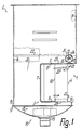
- the media heating unit 1 according to the invention according to FIGS. 1-7 forms a mechanically rigidly connected or welded structural unit to a media storage unit 2, although a detachable connection of the heating unit 1 to the media storage unit 2 is also conceivable.
- the media storage 2 in the illustrated embodiment is a deep-fryer container which is open at the full width for receiving a frying basket, but can also be e.g. B. a closed at the top, provided with inlets and outlets hot water tank or another pressure vessel.
- the heating unit 1 has a one-piece, exclusively made from a single piece of sheet metal by folding or deep drawing, in vertical section U-shaped support 3, on which a single, several or, as shown, a plurality of essentially identical instantaneous water heaters 4 in a substantially uniform distribution both is arranged along its length as well as its depth.
- the two essentially horizontal and mutually parallel U-legs of the carrier 3 form two flange plates 5, 6 of the same length, the upper of which is wider than the lower by less than the diameter or the radius of a continuous-flow heater.
- the U-transverse web of the carrier 3 connecting the two essentially flat flange plates 5, 6 forms its essentially flat or vertical rear wall 7, the distance from which is closest to the instantaneous water heater 4 which is approximately equal to the corresponding distance of the front longitudinal edge of the lower flange plate 6 of the foremost instantaneous water heaters 4.
- a band-shaped, continuous fastening edge 8 which is located in different and mutually transverse planes, is formed, which runs along the longitudinal and narrow edges of the flange plates 5, 6 and along the end edges of the rear wall 7.
- the relatively narrow and substantially constant width of the fastening edge 8 is offset from the rest of the plate part of the respective flange plate 5, 6 and the rear wall 7 by an offset approximately by its material thickness to the outside in such a way that it is opposite to this continuously flat plate part 9 in the area of the flange plates 5, 6 further away from the respective opposite flange plate and set back in the area of the rear wall 7.
- each flow tube 10 advantageously passes continuously in one piece between the two flange plates 5, 6 or the associated offset plate parts 9, so that one or both ends can be fastened directly and without any additional intermediate flange to the respective flange plate 5, 6 directly, for example by a ring weld joint, although a detachable connection, for example according to EP-A-02 38 955, is also conceivable in some applications, to which reference is made here for further details and effects.
- the continuous tubes 10 which have the same outer and inner cross sections over their length, can only be formed by strand sections of a correspondingly long prefabricated tube.
- the media storage 2 is essentially formed by welded walls 11 to 14, which are plate-shaped and are placed at an angle such that they form the upright or the vertical walls.
- the outer boundary of the media store 2 is formed by two walls 11, 12, which are parallel but offset from one another at right angles to their planes by approximately the difference in the width of the flange plates 5, 6, of which the upper from the free longitudinal edge of the upper flange plate 5 to the top of the media storage 2 and the lower from the corresponding longitudinal edge of the lower flange plate 6 to a lower flange edge 15 is sufficient, this lower wall 12 being very low and therefore only in the longitudinal direction of the carrier 3.
- the mounting edge 8 of the carrier 3 is expediently attached with its free edge to several or all of the walls 11 to 14 at an angle such that a fillet defined by two longitudinal edges lying at an angle to one another is created, into which a weld seam can be placed.
- the heating unit 1 forms a braced stiffening profile for the media store 2, which is provided essentially completely within the plan of the walls 11 to 14, that is, does not project outward beyond the media store 2. Since the heating unit 1 is substantially below that in the case of a Fryer for receiving a frying basket serving space of the media store 2, it forms below this usable space also a protruding into the media store 2 displacement body, through which the horizontal cross sections of the media store 2 below the usable space are substantially reduced despite substantially continuous upright walls, so that Filling volume for the media storage 2 can be kept relatively low.
- this also creates a relatively narrow return flow channel starting from the underside of the useful space, which is delimited on one side by the rear wall 7 and on the other side by the opposite wall 14, which is essentially planar and continuous over the useful space and the return flow channel.
- the return flow channel is selected in the manner of an inspection opening so wide that it and the cleaning of the base part are easily possible from above and the cleanliness of the device can be checked.
- a base part 16 with an essentially congruent flange edge 17 is fastened, for example by welding.
- the bottom part 16 has a groove-shaped or shell-shaped curved bottom wall 18, which merges with its gently rising shell edges directly into the flange edge 17 and is provided at its deepest point with a drain socket 19, to which, for example, a check valve can be attached.
- Each flow tube 10 is provided with a single heating resistor 20 in the form of a tubular heating element which extends approximately between the two flange plates 5, 6 and which helically surrounds the outer circumference of the flow tube 10, with configurations after the European patent application mentioned are conceivable.
- the outside diameter of each instantaneous heater 4 is determined by the outside diameter of the filament of the respective heating resistor 20.
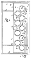
- the water heater 4 are arranged in two rows parallel to each other and to the rear wall 7 such that each water heater of the rear row engages in the gap between two water heaters 4 of the front row and its outer circumference only with a small gap distance from the The outside circumference of these two front water heaters is located.
- the clear distance between adjacent instantaneous water heaters in a row is smaller than their outer diameter and is approximately in the order of half of this outer diameter.
- the number of instantaneous water heaters in the rear row is one instantaneous heater smaller than that in the front row, so that favorable flow conditions result.
- Each heating resistor 20 has two upper and lower connection ends 21 which project substantially towards the open channel side of the carrier 3 and which lie completely within the carrier 3.
- the connection ends 21 of each instantaneous water heater 4 of the rear row are led forward between the two associated adjacent instantaneous water heaters of the front row, so that all connection ends 21 lie essentially in a common wiring plane.
- the Heating resistors of the rear row expediently have opposite spiral pitch compared to the heating resistors of the front row, so that in each case two connecting ends 21 located in the area of the same ends of the associated flow tubes 10 of two adjacent flow heaters 4 of the front and rear rows are directly adjacent to one another at approximately the same height are provided while the other two connection ends 21 of these two instantaneous water heaters run at an angle to one another in a plan view according to FIG. 2.
- the underside of the usable space of the media store 2 is delimited by a type of grate which is formed by cylindrical stiffening bars 22 or identical stiffening profiles lying next to one another in parallel, which are fastened with their ends at the same height to the walls 11, 14 and at a short distance above the upper flange plate 5.
- z. B. two stiffening bars 22, the spacing between them is greater than their distance from the adjacent wall 13. 2
- these stiffening bars 22 above the heating unit 1 have S-shaped curved sections in such a way that they do not cross the clear cross sections of the associated flow tube 10 in plan view, but bypass or circumnavigate and thereby do not disturb the flow.
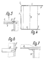
- each end of the stiffening rod 22 is designed as a reduced diameter plug 23 which is inserted into a through hole of the associated wall 11 and whose length is at most as large as the thickness of this wall 11.
- a punctiform welding head 24 is attached from the outside of the wall 11 in the area of the end face of the plug pin 23, which on the one hand defines the stiffening rod 22 and on the other hand seals the bore tightly.
- the attachment of the drain port 19 can be seen, which has an enlarged ring collar at the upper end, with which it is inserted into a closely matched bore in a ring cup-shaped zone of the bottom wall 18 formed downward. From the inside of the bottom wall 18, the drain port 19 is welded to an annular end seam.
- each flow tube 10 has a closely adapted plug-in opening 26, which is delimited by an annular collar 25 formed out of the plate part 9, which extends approximately into the plane of the side of the fastening edge 8 facing away from the opposite flange plate.
- annular collar 25 formed out of the plate part 9, which extends approximately into the plane of the side of the fastening edge 8 facing away from the opposite flange plate.
- the heating unit 1 forms on the underside a multiplicity of grid-like inlet openings 28 in a common plane immediately above the associated rising part of the bottom wall 18 and a corresponding number of outlet openings 29 above it, the medium to be heated being completely on the inside smooth flow tubes 10 is moved upwards by thermosiphon effect. Since all heating resistors 20 are arranged outside of the media-carrying areas or dry, they are not acted upon directly by the medium.
- the heated medium exiting upward from the heating unit 1 flows in a circuit through the part of the media store 2 lying above it and is deflected downward again into the return flow channel 30 lying adjacent to the outlet openings 29 along the bottom wall 18 and back into the inlet openings 28. Because the bottom wall 18 with its part lying on one side of its deepest apex below the return flow channel 30 and with the other part below the inlet openings 28, particularly favorable flow conditions result.
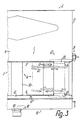
- a sensor arrangement 31 is provided, which is essentially between the front row of instantaneous heaters 4 and the wall 11 is located, extends over most of the length of this row and substantially parallel to it and is attached to one wall 13 with only one end, so that it protrudes substantially freely.
- This sensor arrangement 31 has two rod-shaped or tubular, substantially rectilinear and mutually parallel temperature sensors 32, 33, which are provided in close contact with one another or along a surface line, one temperature sensor 33 being located above the other.
- heating 34 in the form of a hairpin-shaped tubular heater is provided, between the two hairpin legs of which one of the two temperature sensors is arranged such that it is in a common axial plane with these hairpin legs lies.
- the two temperature sensors 32, 33 expediently have different lengths, the temperature sensor 33 lying above the temperature sensor 32 and being further away from the heating 34 and not directly contacting it, like the temperature sensor 32, being shorter, namely approximately half as long as the temperature sensor 32 can.
- the temperature sensors 32, 33 are combined with the heating 34 to form a common structural unit which is detachably fastened to the associated wall 13 by means of a screw connection 35.
- the temperature sensors 32, 33 which are flushed by the medium, are components of two closed, hydraulic expansion systems and are connected to pressure sockets via capillaries (not shown), at least one of which is the contact of a clocking power control unit or a regulator for at least some of the heating resistors 20 as well as for the heating 34, which cannot be addressed as heating for the medium, since its share in the total output of the heating unit 1 is negligible.
- the other temperature sensor 32 which is thermally in particular more closely coupled to the heater 34 and therefore lies between the legs of the hairpin-shaped tubular heater heater 34 and is longer, is provided as a limiter sensor for a temperature limiter for overheating protection and is used to switch off a sufficient number of instantaneous water heaters or all instantaneous water heaters in emergencies , as can occur, for example, due to failure of the temperature-adjustable temperature controller influenced by the temperature sensor 33.
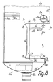
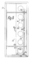
- connection ends 21a of the heating resistor 20a of each instantaneous water heater 4a are aligned approximately at right angles to one another, although a parallel alignment is also conceivable.
- the fastening edge 8a lies in the region of each flange plate 5a or 6a in the plane of the plate part 9a of the flow tubes 10a.
- the stiffening of the carrier 3a is also achieved in this case by bead-like profile formations 36, which are provided in the transition area between the flange plates 5a, 6a and the rear wall 7a and as resilient expansion compensation profiles on the outside thereof, but not on the sides of the flange plates 5a, which are delimited from one another. 6a, protrude.
Landscapes
- Engineering & Computer Science (AREA)
- Mechanical Engineering (AREA)
- Physics & Mathematics (AREA)
- Thermal Sciences (AREA)
- Chemical & Material Sciences (AREA)
- Combustion & Propulsion (AREA)
- Food Science & Technology (AREA)
- General Engineering & Computer Science (AREA)
- Instantaneous Water Boilers, Portable Hot-Water Supply Apparatuses, And Control Of Portable Hot-Water Supply Apparatuses (AREA)
- Frying-Pans Or Fryers (AREA)
- Yarns And Mechanical Finishing Of Yarns Or Ropes (AREA)
- Heating, Cooling, Or Curing Plastics Or The Like In General (AREA)
- Basic Packing Technique (AREA)
Claims (13)
- Unité de chauffage de fluides sous forme d'une unité modulaire (1) préassemblée, destinée à être reliée à des parties de parois (11, 12, 13) d'un réservoir de fluide (2), comprenant un support (3) qui, en vue de la liaison à au moins un dispositif de chauffage à écoulement (4) pour le fluide, comporte deux plaques-brides ou plateaux (5, 6) situés l'un à l'opposé de l'autre, de même que, dans la zone de ces plateaux, au moins une ouverture d'entrée et au moins une ouverture de sortie (28, 29) pour le raccordement au dispositif de chauffage à écoulement (4) concerné, caractérisée en ce que le support (3) de l'unité modulaire (1) préassemblée possède une paroi arrière (7), reliant les plateaux (5, 6), qui forme avec les plateaux (5, 6) le support (3) de section droite en U ou en forme de niche, présentant un bord de fixation (8) continu, longeant les bords des plateaux (5, 6) et de la paroi arrière (7) et servant à la fixation de l'unité de chauffage au réservoir de fluide (2) préassemblé au droit d'une découpe semblable à une fenêtre, devant être fermée par le support (3), lequel est à disposer et à fixer par le bord de fixation (8) aux parties de parois (11, 12, 13) du réservoir de fluide (2), avec raccordement des ouvertures d'entrée et de sortie (28, 29) du dispositif de chauffage à écoulement (4) au réservoir (2), de manière que le fluide puisse s'écouler dans un circuit fermé à partir du réservoir (2) dans le dispositif de chauffage (4), à travers celui-ci pour retourner dans le réservoir (2) et pour ensuite entrer de nouveau dans le dispositif de chauffage (4).
- Unité de chauffage selon la revendication 1, caractérisée en ce que la paroi arrière (7) forme, ensemble avec les plateaux (5, 6) orientés transversalement par rapport à elle en section droite et avec lesquels cette paroi est en particulier d'un seul tenant, un profil en tôle ou analogue, dont les plateaux (5, 6) situés l'un à l'opposé de l'autre, sont raidis mutuellement par au moins un dispositif de chauffage à écoulement (4) et/ou qui forme, avec des délimitations sur au moins trois côtés pour définir en section droite une gouttière en U ou avec des délimitations sur cinq côtés pour définir une cuve, une réception pour le dispositif de chauffage à écoulement (4) concerné.
- Unité de chauffage selon la revendication 1 ou 2, caractérisée en ce qu'au moins un plateau (5, 6) et/ou la paroi arrière (7) présente le bord de fixation (8), qui est notamment continu et en forme de bande, pour la fixation au réservoir de fluide (2) dans la zone des bords délimitant la découpe semblable à une fenêtre dans au moins une paroi (13) du réservoir, l'unité modulaire (1) étant réalisée de préférence pour être fixée à la façon d'un bras en porte-à-faux ou d'un corps déplaceur faisant librement saillie dans le réservoir de fluide (2).
- Unité de chauffage selon une des revendications précédentes, caractérisée en ce qu'au moins un dispositif de chauffage à écoulement (4) avec un tube d'écoulement (10) sont fixés dans la région de l'extrémité concernée à un plateau (5, 6) et que notamment la paroi arrière (7), laquelle est chauffée et située à distance du dispositif de chauffage à écoulement (4) en question, au moins un dispositif de chauffage à écoulement et, éventuellement, les autres parties de parois du support (3) orientées transversalement au plateau (5, 6) concerné, du fait qu'ils sont rigidement reliés entre eux, constituent, pour l'essentiel exclusivement, l'unité modulaire (1) préassemblée à fixer à des portions de parois (11, 12, 13) qui s'y raccordent au-dessus et au-dessous du réservoir de fluide (2) et/ou sont réalisés comme des corps raidisseurs pour ce réservoir (2).
- Unité de chauffage selon une des revendications précédentes, caractérisée en ce que le dispositif de chauffage à écoulement (4) est fixé à au moins un plateau (5, 6), en particulier à partir de sa face d'extrémité correspondante, et que, de préférence, au moins un plateau (5, 6) présente, dans la région du tube d'écoulement (10) ou des tubes d'écoulement (10), une partie de plateau (9) décalée par des coudes par rapport à l'extrémité opposée du dispositif de chauffage (4) concerné, partie de plateau à laquelle est fixée l'extrémité de fixation correspondante du tube d'écoulement (10) en question, et qui s'étend notamment de façon ininterrompue par la paroi arrière (7) entre les deux plateaux (5, 6) en formant le bord de fixation (8) décalé longeant tout le bord extérieur du support (3).
- Unité de chauffage selon une des revendications précédentes, caractérisée en ce qu'au moins un plateau (5, 6) présente, pour un tube d'écoulement (10) d'un dispositif de chauffage à écoulement (4), une ouverture d'emboîtement (26) étroitement adaptée à une extrémité de fixation de ce tube d'écoulement et dans laquelle cette extrémité de fixation est disposée notamment sur une distance égale à l'épaisseur correspondante du plateau (5, 6), de préférence dans un collet (25) faisant saillie dans la même mesure que cette extrémité de fixation.
- Unité de chauffage selon une des revendications précédentes, caractérisée par la prévision, dans la transition entre la paroi arrière (7a) et au moins un plateau (5a, 6a), d'une conformation profilée (36) qui dépasse à la façon d'une moulure de la paroi arrière (7a) et présente des ailes de profil formant de préférence un angle aigu entre elles.
- Unite de chauffage selon une des revendications précédentes, caractérisée en ce que plusieurs dispositifs de chauffage à écoulement (4), essentiellement identiques, sont disposés en au moins une rangée longitudinale, en particulier en quinconce en au moins deux rangées longitudinales à peu près parallèles entre elles, de préférence de manière que la distance moyenne entre ces deux rangées longitudinales soit plus petite que le diamètre extérieur du dispositif de chauffage à écoulement (4) concerné à chaque fois.
- Unité de chauffage selon une des revendications précédentes, caractérisée en ce qu'une résistance chauffante (20), constituant en particulier un corps tubulaire chauffant de forme en hélice, fixé par brasage ou analogue, est disposé à la périphérie extérieure du dispositif de chauffage à écoulement (4), en particulier sur la périphérie extérieure d'un tube d'écoulement (10) correspondant, et que, de préférence, toutes les extrémités de raccordement ou connexions (21) des résistances chauffantes (20) sont situées pour l'essentiel du côté des dispositifs de chauffage (4) éloigné de la paroi arrière (7).
- Unité de chauffage selon une des revendications précédentes, caractérisée en ce qu'au moins une unité modulaire (1) préassemblée est fixée au réservoir de fluide (2) et constitue une saillie en forme de boîte pénétrant pour l'essentiel sans contact dans le réservoir de fluide (2), saillie au-dessous de laquelle et/ou au-dessus de laquelle le réservoir de fluide (2) présente des sections droites intérieures essentiellement constantes.
- Unité de chauffage selon une des revendications précédentes, caractérisée en ce qu'il lui est coordonnée au moins une barre raidisseuse (22) placée au-dessus et transversalement à la paroi arrière (7) et reliant entre elles des portions de parois (11, 14) associées, barre qui est de préférence incurvée, dans une vue de dessus, autour d'au moins une ouverture de sortie (29) d'un dispositif de chauffage à écoulement (4) situé sous elle.
- Unité de chauffage selon une des revendications précédentes, caractérisée en ce qu'au moins un capteur de température (32, 33) d'un appareil de réglage de la température est installé directement au-dessus d'au moins une ouverture de sortie de fluide (29) de l'unité de chauffage, l'appareil de réglage comprenant de préférence deux capteurs de température (32, 33) tubulaires remplis d'un liquide de dilatation et placés à proximité immédiate l'un de l'autre, capteurs qui sont exposés, à travers des couplages thermiques différents, à un corps chauffant de détection (34), tel qu'un corps chauffant tubulaire ayant la forme d'une épingle à cheveux.
- Unité de chauffage selon une des revendications précédentes, caractérisée en ce qu'un puisard, courbé de préférence en cuvette plate ou en gouttière, est prévu à une faible distance directement sous un plateau inférieur (6), la paroi de fond (18) du puisard étant située au-dessous d'au moins une ouverture d'entrée de fluide (28) de l'unité de chauffage et/ou montant vers un côté ouvert du support (3).
Priority Applications (1)
| Application Number | Priority Date | Filing Date | Title |
|---|---|---|---|
| AT89101313T ATE103697T1 (de) | 1988-02-12 | 1989-01-26 | Medien-heizeinheit. |
Applications Claiming Priority (2)
| Application Number | Priority Date | Filing Date | Title |
|---|---|---|---|
| DE3804327A DE3804327A1 (de) | 1988-02-12 | 1988-02-12 | Medien-heizeinheit |
| DE3804327 | 1988-02-12 |
Publications (2)
| Publication Number | Publication Date |
|---|---|
| EP0327889A1 EP0327889A1 (fr) | 1989-08-16 |
| EP0327889B1 true EP0327889B1 (fr) | 1994-03-30 |
Family
ID=6347238
Family Applications (1)
| Application Number | Title | Priority Date | Filing Date |
|---|---|---|---|
| EP89101313A Expired - Lifetime EP0327889B1 (fr) | 1988-02-12 | 1989-01-26 | Unité pour chauffer des fluides |
Country Status (6)
| Country | Link |
|---|---|
| US (1) | US4998007A (fr) |
| EP (1) | EP0327889B1 (fr) |
| JP (1) | JPH01239341A (fr) |
| AT (1) | ATE103697T1 (fr) |
| DE (2) | DE3804327A1 (fr) |
| YU (1) | YU30989A (fr) |
Families Citing this family (3)
| Publication number | Priority date | Publication date | Assignee | Title |
|---|---|---|---|---|
| US5961866A (en) * | 1996-03-27 | 1999-10-05 | Alto-Shaam, Inc. | Food heating unit |
| FR2750590B1 (fr) * | 1996-07-03 | 1998-10-09 | Seb Sa | Friteuse a cuve amovible |
| FR2789872B1 (fr) * | 1999-02-19 | 2001-05-18 | Seb Sa | Dispositif de securite pour appareil electrique de cuisson a cuve amovible |
Family Cites Families (12)
| Publication number | Priority date | Publication date | Assignee | Title |
|---|---|---|---|---|
| US696599A (en) * | 1901-04-10 | 1902-04-01 | Milton H Shoenberg | Electric water-heater. |
| US817593A (en) * | 1903-08-10 | 1906-04-10 | James A Howze | Electric water-heater. |
| FR857463A (fr) * | 1939-07-07 | 1940-09-14 | Chaudière électrique à plusieurs foyers indépendants et amovibles, pour toutes applications et notamment pour le chauffage central | |
| FR879421A (fr) * | 1941-02-25 | 1943-02-23 | Chauffe-eau électrique | |
| FR887455A (fr) * | 1941-05-29 | 1943-11-15 | Chaudière électrique | |
| US2582103A (en) * | 1949-03-09 | 1952-01-08 | Clegg Carlton | Electric heating of wash boilers and the like |
| FR1526903A (fr) * | 1966-10-18 | 1968-05-31 | Perfectionnement aux friteuses à éléments chauffants immergés | |
| CH573739A5 (fr) * | 1973-09-25 | 1976-03-31 | Schmid Charles | |
| DE3329793A1 (de) * | 1983-08-18 | 1985-02-28 | E.G.O. Elektro-Geräte Blanc u. Fischer, 7519 Oberderdingen | Elektrische beheizung fuer fluessigkeitsbehaelter |
| IT8434061U1 (it) * | 1984-10-10 | 1986-04-10 | Zanussi Grandi Impianti Spa | Girante per dispositivo di riscaldamento dell'olio nelle friggitrici |
| DE3610235A1 (de) * | 1986-03-26 | 1987-10-01 | Ego Elektro Blanc & Fischer | Friteuse |
| DE8619074U1 (de) * | 1986-07-16 | 1986-11-27 | Siemens AG, 1000 Berlin und 8000 München | Elektrischer Durchlauferhitzer |
-
1988
- 1988-02-12 DE DE3804327A patent/DE3804327A1/de not_active Withdrawn
-
1989
- 1989-01-26 DE DE89101313T patent/DE58907313D1/de not_active Expired - Fee Related
- 1989-01-26 EP EP89101313A patent/EP0327889B1/fr not_active Expired - Lifetime
- 1989-01-26 AT AT89101313T patent/ATE103697T1/de not_active IP Right Cessation
- 1989-02-01 US US07/305,601 patent/US4998007A/en not_active Expired - Fee Related
- 1989-02-08 JP JP1027768A patent/JPH01239341A/ja active Pending
- 1989-02-09 YU YU30989A patent/YU30989A/sh unknown
Also Published As
| Publication number | Publication date |
|---|---|
| ATE103697T1 (de) | 1994-04-15 |
| JPH01239341A (ja) | 1989-09-25 |
| US4998007A (en) | 1991-03-05 |
| DE58907313D1 (de) | 1994-05-05 |
| EP0327889A1 (fr) | 1989-08-16 |
| DE3804327A1 (de) | 1989-08-24 |
| YU30989A (sh) | 1992-07-20 |
Similar Documents
| Publication | Publication Date | Title |
|---|---|---|
| EP0135707B1 (fr) | Friteuse électrique | |
| DE2163951C3 (de) | Wärmeaustauscher mit einem im Inneren eines von Fluid durchströmten Rohres angeordneten Störelement | |
| EP0238955B1 (fr) | Dispositif de chauffage de fluides | |
| EP0209868A2 (fr) | Réchauffeur électrique pour réservoir de liquides | |
| EP1582732B1 (fr) | Distributeur avec dispositif de chauffage et support d'échangeur de chaleur pour un réservoir avec fluide servant à décomposer et/ou congeler | |
| EP0193863A2 (fr) | Générateur de vapeur, en particulier pour appareils de cuisson | |
| EP0327889B1 (fr) | Unité pour chauffer des fluides | |
| DE3826244A1 (de) | Oelkuehler | |
| EP1101068A1 (fr) | Four de cuisson a sonde de temperature | |
| DE3407965A1 (de) | Grillplatte | |
| DE7927253U1 (de) | Waermeuebertrager, insbesondere fuer gas- oder oelbeheizte wassererhitzer | |
| EP0230496B1 (fr) | Dispositif de réglage de température, en particulier pour liquides ou gaz | |
| EP1760407A1 (fr) | Distributeur pour système de chauffage et de refroidissement | |
| DE2738036A1 (de) | Heizelement fuer die raumheizung | |
| DE3807116A1 (de) | Wasserheizer, insbesondere gliederkessel, sowie kesselglieder fuer solche gliederkessel | |
| DE19728246B4 (de) | Rohrheizkörper für Räume | |
| EP3953646B1 (fr) | Appareil de chauffage électrique | |
| DE4029513A1 (de) | Medienerhitzer fuer fluessigkeitsbetriebene heizkoerper | |
| DE2745912C2 (de) | Wärmeübertrager | |
| DE102004022302A1 (de) | Verdampferelement für flüssige Brennstoffe | |
| EP0077993B1 (fr) | Chaudière à accumulation | |
| DE1237251B (de) | Brenneranlage fuer pulsierende Verbrennung | |
| DE1944441U (de) | Heizkoerper. | |
| DE29617733U1 (de) | Heizkörper für Zentralheizungsanlagen, insbesondere Badezimmer-Heizkörper | |
| DE4029512A1 (de) | Medienerhitzer, insbesondere dampferzeuger |
Legal Events
| Date | Code | Title | Description |
|---|---|---|---|
| PUAI | Public reference made under article 153(3) epc to a published international application that has entered the european phase |
Free format text: ORIGINAL CODE: 0009012 |
|
| AK | Designated contracting states |
Kind code of ref document: A1 Designated state(s): AT CH DE ES FR GB IT LI SE |
|
| 17P | Request for examination filed |
Effective date: 19891223 |
|
| 17Q | First examination report despatched |
Effective date: 19910115 |
|
| GRAA | (expected) grant |
Free format text: ORIGINAL CODE: 0009210 |
|
| AK | Designated contracting states |
Kind code of ref document: B1 Designated state(s): AT CH DE ES FR GB IT LI SE |
|
| PG25 | Lapsed in a contracting state [announced via postgrant information from national office to epo] |
Ref country code: SE Free format text: THE PATENT HAS BEEN ANNULLED BY A DECISION OF A NATIONAL AUTHORITY Effective date: 19940330 Ref country code: ES Free format text: THE PATENT HAS BEEN ANNULLED BY A DECISION OF A NATIONAL AUTHORITY Effective date: 19940330 |
|
| REF | Corresponds to: |
Ref document number: 103697 Country of ref document: AT Date of ref document: 19940415 Kind code of ref document: T |
|
| REF | Corresponds to: |
Ref document number: 58907313 Country of ref document: DE Date of ref document: 19940505 |
|
| GBT | Gb: translation of ep patent filed (gb section 77(6)(a)/1977) |
Effective date: 19940421 |
|
| ITF | It: translation for a ep patent filed | ||
| ET | Fr: translation filed | ||
| PG25 | Lapsed in a contracting state [announced via postgrant information from national office to epo] |
Ref country code: GB Effective date: 19950126 Ref country code: AT Effective date: 19950126 |
|
| PG25 | Lapsed in a contracting state [announced via postgrant information from national office to epo] |
Ref country code: LI Effective date: 19950131 Ref country code: CH Effective date: 19950131 |
|
| PLBE | No opposition filed within time limit |
Free format text: ORIGINAL CODE: 0009261 |
|
| STAA | Information on the status of an ep patent application or granted ep patent |
Free format text: STATUS: NO OPPOSITION FILED WITHIN TIME LIMIT |
|
| PGFP | Annual fee paid to national office [announced via postgrant information from national office to epo] |
Ref country code: DE Payment date: 19950320 Year of fee payment: 7 |
|
| 26N | No opposition filed | ||
| GBPC | Gb: european patent ceased through non-payment of renewal fee |
Effective date: 19950126 |
|
| PG25 | Lapsed in a contracting state [announced via postgrant information from national office to epo] |
Ref country code: FR Effective date: 19950929 |
|
| REG | Reference to a national code |
Ref country code: CH Ref legal event code: PL |
|
| REG | Reference to a national code |
Ref country code: FR Ref legal event code: ST |
|
| PG25 | Lapsed in a contracting state [announced via postgrant information from national office to epo] |
Ref country code: DE Effective date: 19961001 |
|
| PG25 | Lapsed in a contracting state [announced via postgrant information from national office to epo] |
Ref country code: IT Free format text: LAPSE BECAUSE OF NON-PAYMENT OF DUE FEES;WARNING: LAPSES OF ITALIAN PATENTS WITH EFFECTIVE DATE BEFORE 2007 MAY HAVE OCCURRED AT ANY TIME BEFORE 2007. THE CORRECT EFFECTIVE DATE MAY BE DIFFERENT FROM THE ONE RECORDED. Effective date: 20050126 |