EP0327946A2 - Antiblockiersteuerungssystem für Kraftfahrzeuge - Google Patents
Antiblockiersteuerungssystem für Kraftfahrzeuge Download PDFInfo
- Publication number
- EP0327946A2 EP0327946A2 EP89101728A EP89101728A EP0327946A2 EP 0327946 A2 EP0327946 A2 EP 0327946A2 EP 89101728 A EP89101728 A EP 89101728A EP 89101728 A EP89101728 A EP 89101728A EP 0327946 A2 EP0327946 A2 EP 0327946A2
- Authority
- EP
- European Patent Office
- Prior art keywords
- pressure reduction
- wheel speed
- time point
- lock control
- speed
- Prior art date
- Legal status (The legal status is an assumption and is not a legal conclusion. Google has not performed a legal analysis and makes no representation as to the accuracy of the status listed.)
- Granted
Links
Images


Classifications
-
- B—PERFORMING OPERATIONS; TRANSPORTING
- B60—VEHICLES IN GENERAL
- B60T—VEHICLE BRAKE CONTROL SYSTEMS OR PARTS THEREOF; BRAKE CONTROL SYSTEMS OR PARTS THEREOF, IN GENERAL; ARRANGEMENT OF BRAKING ELEMENTS ON VEHICLES IN GENERAL; PORTABLE DEVICES FOR PREVENTING UNWANTED MOVEMENT OF VEHICLES; VEHICLE MODIFICATIONS TO FACILITATE COOLING OF BRAKES
- B60T8/00—Arrangements for adjusting wheel-braking force to meet varying vehicular or ground-surface conditions, e.g. limiting or varying distribution of braking force
- B60T8/17—Using electrical or electronic regulation means to control braking
- B60T8/176—Brake regulation specially adapted to prevent excessive wheel slip during vehicle deceleration, e.g. ABS
- B60T8/1763—Brake regulation specially adapted to prevent excessive wheel slip during vehicle deceleration, e.g. ABS responsive to the coefficient of friction between the wheels and the ground surface
- B60T8/17636—Microprocessor-based systems
-
- B—PERFORMING OPERATIONS; TRANSPORTING
- B60—VEHICLES IN GENERAL
- B60T—VEHICLE BRAKE CONTROL SYSTEMS OR PARTS THEREOF; BRAKE CONTROL SYSTEMS OR PARTS THEREOF, IN GENERAL; ARRANGEMENT OF BRAKING ELEMENTS ON VEHICLES IN GENERAL; PORTABLE DEVICES FOR PREVENTING UNWANTED MOVEMENT OF VEHICLES; VEHICLE MODIFICATIONS TO FACILITATE COOLING OF BRAKES
- B60T8/00—Arrangements for adjusting wheel-braking force to meet varying vehicular or ground-surface conditions, e.g. limiting or varying distribution of braking force
- B60T8/17—Using electrical or electronic regulation means to control braking
- B60T8/173—Eliminating or reducing the effect of unwanted signals, e.g. due to vibrations or electrical noise
Definitions
- This invention relates to a novel and improved anti-lock control system for motor vehicles, which is operative to prevent the wheels of the motor vehicle from being locked during braking operation of the motor vehicle.
- anti-lock control is effected by means of microcomputers such that hold valves and decay valves comprising electromagnetic valves are opened and closed on the basis of electrical signals representing wheel speeds sensed by wheel speed sensors, thereby increasing, holding or reducing the brake hydraulic pressure, for the purpose of securing improved steering performance and running stability of the motor vehicle, while at the same time shortening the braking distance.
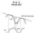
- Figure 1 of the accompanying drawings illustrates, by way of example, manners in which wheel speed Vw, wheel acceleration and deceleration dVw/dt and brake hydraulic pressure Pw are varied during the operation of the conventional anti-lock control system, together with hold signal HS and decay signal DS for opening and closing hold valves and decay valves as , disclosed in U. S. Patent No. 4,741,580.
- a reference wheel speed Vr is set up which is lower by a predetermined amount ⁇ V than the wheel speed Vw and follows the latter with such a speed difference.
- a predetermined threshold level say - 1.1G at time t1
- the hold signal HS is generated so that the hold valves are closed, thus holding the brake hydraulic pressure Pw.
- the wheel speed Vw is further decreased.
- the wheel speed Vw and the reference wheel speed Vr become equal to each other, and a first cycle of anti-lock control is started; and the decay signal DS is generated, by which the decay valves are opened so that reduction of the brake hydraulic pressure Pw is started.
- the wheel speed Vw is changed from increase to decrease at time t4 when a low peak VL of the wheel speed Vw occurs.
- the decay signal DS is interrupted as shown in Figure 1, and as a result the decay valves are closed so that the reduction of the brake hydraulic pressure Pw is stopped and thus the brake hydraulic pressure is held.
- the brake hydraulic pressure Pw is again increased.
- the buildup of the brake hydraulic pressure Pw is effected in such a manner that the brake hydraulic pressure Pw is alternately increased and held in succession by the fact that the hold signal HS is turned on and off mincingly, i.
- the time period Tx of the initial brake hydraulic pressure buildup occurring at the time t7 is determined on the basis of calculation of the average acceleration (Vc - Vb )/ ⁇ T over the time interval ⁇ T between the time t5 and the time t6 (the average acceleration depends on the friction coefficient ⁇ of the road surface), and the time period of the subsequent pressure holding or pressure buildup is determined on the basis of the acceleration or deceleration of the wheel which is detected immediately prior to the pressure holding or pressure buildup.
- the brake hydraulic pressure increasing, holding and reducing modes are effected in combination as mentioned above, and thus the wheel speed Vw can be controlled so that the vehicle speed can be decrease, while the wheels of the motor vehicle are prevented from being locked.
- wheel speed Vw which is used as a reference speed is computed on the basis of a frequency signal derived from a speed sensor provided in association with the wheel and is subjected to filtering in the range from +30G to -30G for example to prevent faulty operation due to noise.
- a predetermined period of time is required so that the computed speed Vw shown by a solid line in Figure 2 tends to be delayed by a certain time period say 10 to 16 ms with respect to the real wheel speed Vw′ shown by a one-dotted chain line.
- the pressure reduction should be interrupted at a time point P′ when a low peak of the real wheel speed Vw′ occurs, and thereafter the brake hydraulic pressure should be held as shown by a one-dotted chain line Pw′ in Figure 2; actually, however, it is at a time point P later by a certain time period than the time point P′ that the pressure reduction is interrupted so that the brake hydraulic pressure Pw is correspondingly further reduced.
- the decreasing gradient of the brake hydraulic pressure as the anti-lock control is being effected is higher than the increasing gradient; thus, the brake hydraulic pressure is excessively reduced because of the delayed interruption of the pressure reduction.
- an object of the present invention to provide an anti-lock control system for motor vehicle, which is so designed as to prevent the braking distance of the motor vehicle from being increased by excessive reduction of brake hydraulic pressure for a medium- or high- ⁇ road surface, while at the same time avoiding occurrence of vibration in the motor vehicle which tends to be caused due to the excessive reduction of the brake hydraulic pressure.
- an anti-lock control system wherein a normal pressure reduction period for brake hydraulic pressure is set up; and for a medium- or high- ⁇ road surface, when the normal pressure reduction period elapses at time point that is later than a time point when pressure reduction is started but earlier than a time point when a low of wheel speed is reached, the pressure reduction is interrupted at the end of the normal pressure reduction period.
- an anti-lock control system wherein a normal pressure reduction period is set up; a pressure reduction resuming threshold speed is set up which is lower than and follows, in a predetermined relation, a computed vehicle speed which is computed on the basis of the highest one of four wheel speeds; for a medium- or high- ⁇ road surface, when the normal pressure reduction period elapses at a time point that is later than a time point when reduction of brake hydraulic pressure is started but earlier than a time point when the wheel speed becomes equal to or lower than the pressure reduction resuming threshold speed, the pressure reduction is interrupted at the end of the normal pressure reduction periods.
- a normal pressure reduction period for a a medium- or high- ⁇ road surface is set up; for such a road surface, pressure reduction of brake hydraulic pressure is interrupted at a time point when the normal pressure reduction period elapses, so that excessive reduction of the brake hydraulic pressure is prevented, thereby making it possible to shorten the braking distance. It is also possible to avoid occurrence of vibration in the motor vehicle which tends to be caused by such excessive reduction of the brake hydraulic pressure.
- a pressure reduction resuming threshold speed is set up , and control is effected in such a manner that pressure reduction is always effected when the wheel speed is lower than the pressure reduction resuming threshold speed so that even when rapidly falling, the wheel speed can be recovered from the falling state, thereby making it possible to prevent the wheel from being locked.
- FIG. 3 there are shown, in a block diagram, a three-channel type anti-lock control system embodying the present invention, wherein outputs of wheel speed sensors 1 to 4 are passed to and computed in computing circuits 5 to 8 , from which signals representing wheel speeds Vw1 to Vw4 are derived.
- Lefthand front wheel speed Vw1 and righthand front wheel speed Vw2 are respectively provided directly to first and second control logic circuits 9 and 10 as first and second channel speeds Vs1 and Vs2.
- Lower one of lefthand rear wheel speed Vw3 and righthand rear wheel speed Vw4 is selected by a select-low circuit 11 and is provided to a third control logic circuit 12 as a third channel speed Vs3.
- the opening/closing operation of hold valves HV and decay valves DV is controlled by using each of the channel speeds Vs1 to Vs3 as a control object wheel speed Vw which will be referred to as wheel speed Vw hereinafter.
- the respective signals representing the wheel speeds Vw1 to Vw4 are passed to a computing circuit 13 which in turn provided a computed vehicle speed.
- the highest one of the four wheel speeds Vw1 to Vw4 is selected and subjected to filtering of its acceleration and deceleration in a range from +1G to -1G so that the computed vehicle speed Vv is provided which in turn is passed to the control logic circuits 9, 10 and 12.
- the computed vehicle speed Vv is also provided to a declaration gradient judging circuit 14.
- a signal representing the deceleration gradient judged by the circuit 14 is transmitted to the control logic circuits 9, 10 and 12.
- the deceleration gradient of the computed vehicle speed Vv represents the friction coefficient ⁇ of the road surface.
- the deceleration gradient value of the computed vehicle speed Vv corresponding to a lower limit value ⁇ 1 for the friction coefficient of a medium- ⁇ road surface is set at 0.2G; and when the deceleration gradient is steeper than 0.2G, the road surface is judged as medium- or high- ⁇ road surface.
- judgment of the deceleration gradient of the computed vehicle speed Vv is made on the basis of the deceleration gradient which occurs during the time period from a time point when the anti-lock control is commenced to a time point when the subsequent buildup of the brake hydraulic pressure is started; and for second and succeeding cycles of the anti-lock control process, judgment of the deceleration gradient is made on the basis of the deceleration which occurs during the time period from a time point when buildup of the brake hydraulic pressure is started to a time point when the next buildup of the brake hydraulic pressure is started.
- the control logic circuits 9, 10 and 12 are respectively provided with pressure reduction period judging sections 15, 16 and 17 including switches SW1 to SW3 which are turned on, so that the sections 15 to 17 are operated, during the time period from a time point when pressure reduction is started to a time point when the pressure reduction is interrupted (when a low peak of the wheel speed Vw occurs), i.e., from time t3 to time t4 in Figure 1.
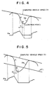
- normal pressure reduction time T1 say 16 to 24 ms for the brake hydraulic pressure is set up; in the case where it is judged by the deceleration gradient judging circuit 14 that the deceleration gradient of the computed vehicle speed Vv is steeper than 0.2G, i.e., in she case where the road surface is judged as a medium- or high- ⁇ road surface, the brake hydraulic pressure reduction is interrupted when the normal pressure reduction time T1 has elapsed at a time point B later than a time point A when the pressure reduction is started but earlier than a time point C when a low peak of the wheel speed Vw occurs, as shown in Figure 4.
- the pressure reduction is interrupted at the time point C as shown by one-dotted chain line in Figure 4, whereas with the system of the present invention, as mentioned just above, the pressure reduction is interrupted at the time point B so that the brake hydraulic pressure is prevented from being excessively reduced for a medium- or high- ⁇ road surface.
- FIG. 8 is a flow chart showing a control routine executed by the pressure reduction period judging sections 15 to 17.
- step S1 judgment is made as to whether or not the normal pressure reduction period T1 elapses after pressure reduction is started.
- the result of the judgment at the step S1 is"NO" until the normal pressure reduction period T1 elapse, and thus the process proceeds to step S2 where judgment is made as to whether or not the wheel speed Vw is lower than the the pressure reduction resuming threshold VT1.
- the result of the judgment at the step S2 is "NO" until the wheel speed Vw reaches the pressure reduction resuming threshold VT1, and thus the process proceeds to step S3 where judgment is made as to whether or not a low peak of the wheel speed Vw is reached.
- the process returns to the step S1 until a low peak of the wheel speed Vw occurs.
- the result of the judgment at the step S3 is "YES”, and a hold mode is established at step S2.
- the decay valves are turned off (closed) while the hold valves remain turned on (closed), so that the pressure reduction is interrupted.
- the process returns to the step S1.
- step S6 When the result of the judgment at the step S6 is "YES" the process proceeds to the next step S7 where judgment is made as to whether or not the friction coefficient of the road surface is equal to or higher than a lower limit value ⁇ 1 for the friction coefficient of a medium- ⁇ road surface.
- This judgment is made through the judgment with respect to the deceleration of the computed vehicle speed Vv as described above. More specifically, the road surface is judged as medium- or high- ⁇ road surface when the deceleration gradient of the computed vehicle speed Vv is steeper than 0.2G.
- step S8 judgment is made as to whether or not the average deceleration AVG of the wheel speed Vw occurring during the time period from the pressure reduction starting point to the time point when the normal pressure reduction period T1 elapses, is equal to or higher than a predetermined value G1, say 10G.
- a predetermined value G1 say 10G.
- step S2 When it is judged at the step S2 that the wheel speed Vw is lower than the pressure reduction resuming threshold VT1, the process proceeds to step S10 where while the hold valves remain turned on (closed), the decay valves are turned on (opened), so that the brake hydraulic pressure is reduced again.
- step S3 When it is judged at the next step S3 that a low peak of the wheel speed Vw occurs, a hold mode is established at step S4, and the pressure reduction is interrupted at step S5.
- step S2 When it is judged at the step S2 that the wheel speed Vw is not lower than the pressure reduction resuming threshold VT1, the process proceeds to step S3 while the pressure reduction remains interrupted.
- step S6 or S7 when the result of the judgment at the step S6 or S7 is"NO", or when the result of the judgment at the step S8 is "YES”, the pressure reduction is not interrupted, and the process proceeds to the step S2; when the result of the judgment at the step S2 indicates that Vw is equal to or lower than VT1, the process proceeds to step S10 so that the pressure reduction is continued until and interrupted at a time point when a low peak of the wheel speed Vw is reached.
Landscapes
- Engineering & Computer Science (AREA)
- Transportation (AREA)
- Mechanical Engineering (AREA)
- Microelectronics & Electronic Packaging (AREA)
- Regulating Braking Force (AREA)
Applications Claiming Priority (2)
| Application Number | Priority Date | Filing Date | Title |
|---|---|---|---|
| JP25705/88 | 1988-02-08 | ||
| JP63025705A JP2688909B2 (ja) | 1988-02-08 | 1988-02-08 | アンチロック制御方法 |
Publications (3)
| Publication Number | Publication Date |
|---|---|
| EP0327946A2 true EP0327946A2 (de) | 1989-08-16 |
| EP0327946A3 EP0327946A3 (de) | 1991-12-11 |
| EP0327946B1 EP0327946B1 (de) | 1995-01-11 |
Family
ID=12173204
Family Applications (1)
| Application Number | Title | Priority Date | Filing Date |
|---|---|---|---|
| EP89101728A Expired - Lifetime EP0327946B1 (de) | 1988-02-08 | 1989-02-01 | Antiblockiersteuerungssystem für Kraftfahrzeuge |
Country Status (5)
| Country | Link |
|---|---|
| US (1) | US4929035A (de) |
| EP (1) | EP0327946B1 (de) |
| JP (1) | JP2688909B2 (de) |
| DE (1) | DE68920447T2 (de) |
| ES (1) | ES2068212T3 (de) |
Cited By (3)
| Publication number | Priority date | Publication date | Assignee | Title |
|---|---|---|---|---|
| EP0442500A3 (en) * | 1990-02-16 | 1992-12-23 | Akebono Brake Industry Co., Ltd. | Estimating road friction coefficient |
| EP0621162A3 (de) * | 1993-04-21 | 1997-08-27 | Japan Electronics Ind Ltd | Verfahren zur Kraftfahrzeug-Antiblokierbremssteuerung, und Verfahren zur Herausfindung eines Steuerungs-Punktes. |
| US6241324B1 (en) | 1993-08-25 | 2001-06-05 | Japan Electronics Industry, Limited | Method of controlling anti-lock brake system for vehicles and method of finding control point in ABS |
Families Citing this family (14)
| Publication number | Priority date | Publication date | Assignee | Title |
|---|---|---|---|---|
| EP0363570B1 (de) * | 1988-10-13 | 1996-02-21 | Japan Electronics Industry, Ltd. | Strassenoberflächen-Reibungsaufnehmer und Strassenoberflächen-Reibungskoeffizienten-Aufnehmer und Fahrzeug-Blockierschutz-Bremsanlage |
| JP2767271B2 (ja) * | 1989-02-28 | 1998-06-18 | 曙ブレーキ工業株式会社 | 車両のアンチロック制御方法 |
| DE3915879C5 (de) * | 1989-05-16 | 2005-07-14 | Continental Teves Ag & Co. Ohg | Verfahren und Schaltungsanordnung zur Auswertung der Radgeschwindigkeitssignale für eine Blockierschutz- oder Antriebsschlupfregelung |
| US5109339A (en) * | 1989-05-23 | 1992-04-28 | Toyota Jidosha Kabushiki Kaisha | Anti-lock brake control apparatus including means for detecting average wheel acceleration for determining brake pressure decrease time |
| JP2659585B2 (ja) * | 1989-05-26 | 1997-09-30 | 株式会社デンソー | 車輪速度処理装置 |
| JPH0367770A (ja) * | 1989-08-08 | 1991-03-22 | Akebono Brake Res & Dev Center Ltd | 車両のアンチロック制御方法 |
| JPH03246157A (ja) * | 1990-02-23 | 1991-11-01 | Toyota Motor Corp | アンチスキッド制御装置 |
| JP2855464B2 (ja) * | 1990-05-09 | 1999-02-10 | 曙ブレーキ工業株式会社 | 車両のアンチロック制御方法 |
| JP2929388B2 (ja) * | 1990-06-29 | 1999-08-03 | 曙ブレーキ工業株式会社 | 車両のアンチロック制御装置 |
| US5236255A (en) * | 1990-10-16 | 1993-08-17 | Aisin Seiki Kabushiki Kaisha | Anti-skid control system having dual pressure increase modes |
| JPH04191158A (ja) * | 1990-11-27 | 1992-07-09 | Mazda Motor Corp | 車両のアンチスキッドブレーキ装置 |
| JP2583367B2 (ja) * | 1991-07-22 | 1997-02-19 | 日産自動車株式会社 | 制動力制御装置 |
| DE4210576C1 (de) * | 1992-03-31 | 1993-08-05 | Temic Telefunken Microelectronic Gmbh, 7100 Heilbronn, De | |
| US5229725A (en) * | 1992-04-07 | 1993-07-20 | Moore Products Co. | Electrical fault detector in remote systems using a saturable core |
Family Cites Families (13)
| Publication number | Priority date | Publication date | Assignee | Title |
|---|---|---|---|---|
| US3545817A (en) * | 1969-01-21 | 1970-12-08 | Gordon W Yarber | Brake control mechanism |
| DE2758529A1 (de) * | 1977-12-28 | 1979-08-16 | Bosch Gmbh Robert | Antiblockierregelsystem |
| SU1054146A1 (ru) * | 1981-07-16 | 1983-11-15 | Egin Nikolaj L | Управл ющее устройство дл противоблокировочной тормозной системы автомобил |
| DE3201929A1 (de) * | 1982-01-22 | 1983-08-04 | Robert Bosch Gmbh, 7000 Stuttgart | Antiblockiersystem |
| JPS6035646A (ja) * | 1983-08-09 | 1985-02-23 | Nippon Denso Co Ltd | アンチスキツド制御装置 |
| JPS6035647A (ja) * | 1983-08-09 | 1985-02-23 | Nippon Denso Co Ltd | アンチスキツド制御装置 |
| JPS6181261A (ja) * | 1984-09-27 | 1986-04-24 | Akebono Brake Ind Co Ltd | アンチスキツドシステムにおける油圧制御方法 |
| JP2500857B2 (ja) * | 1985-04-13 | 1996-05-29 | 日本電装株式会社 | アンチスキツド制御装置 |
| US4741580A (en) * | 1985-08-02 | 1988-05-03 | Akebono Brake Industry Co., Ltd. | Anti-skid control system for motor vehicle |
| JPH0678059B2 (ja) * | 1985-11-20 | 1994-10-05 | トキコ株式会社 | アンチスキツド制御装置 |
| JPH0729598B2 (ja) * | 1985-12-27 | 1995-04-05 | 曙ブレーキ工業株式会社 | アンチスキツド制御方法 |
| DE3610184A1 (de) * | 1986-03-26 | 1987-10-01 | Bosch Gmbh Robert | Antiblockierregelsystem |
| US4769753A (en) * | 1987-07-02 | 1988-09-06 | Minnesota Mining And Manufacturing Company | Compensated exponential voltage multiplier for electroluminescent displays |
-
1988
- 1988-02-08 JP JP63025705A patent/JP2688909B2/ja not_active Expired - Lifetime
-
1989
- 1989-02-01 EP EP89101728A patent/EP0327946B1/de not_active Expired - Lifetime
- 1989-02-01 DE DE68920447T patent/DE68920447T2/de not_active Expired - Fee Related
- 1989-02-01 ES ES89101728T patent/ES2068212T3/es not_active Expired - Lifetime
- 1989-02-07 US US07/307,617 patent/US4929035A/en not_active Expired - Fee Related
Cited By (3)
| Publication number | Priority date | Publication date | Assignee | Title |
|---|---|---|---|---|
| EP0442500A3 (en) * | 1990-02-16 | 1992-12-23 | Akebono Brake Industry Co., Ltd. | Estimating road friction coefficient |
| EP0621162A3 (de) * | 1993-04-21 | 1997-08-27 | Japan Electronics Ind Ltd | Verfahren zur Kraftfahrzeug-Antiblokierbremssteuerung, und Verfahren zur Herausfindung eines Steuerungs-Punktes. |
| US6241324B1 (en) | 1993-08-25 | 2001-06-05 | Japan Electronics Industry, Limited | Method of controlling anti-lock brake system for vehicles and method of finding control point in ABS |
Also Published As
| Publication number | Publication date |
|---|---|
| JP2688909B2 (ja) | 1997-12-10 |
| EP0327946A3 (de) | 1991-12-11 |
| DE68920447T2 (de) | 1995-06-29 |
| DE68920447D1 (de) | 1995-02-23 |
| ES2068212T3 (es) | 1995-04-16 |
| EP0327946B1 (de) | 1995-01-11 |
| US4929035A (en) | 1990-05-29 |
| JPH01202564A (ja) | 1989-08-15 |
Similar Documents
| Publication | Publication Date | Title |
|---|---|---|
| EP0327946B1 (de) | Antiblockiersteuerungssystem für Kraftfahrzeuge | |
| US4883325A (en) | Anti-lock brake control system for motor vehicles | |
| US4991910A (en) | Anti-lock control system for motor vehicles | |
| US4762375A (en) | Anti-skid control system for motor vehicles | |
| US4797825A (en) | Anti-skid control system for motor vehicles | |
| JP3352497B2 (ja) | 車両のアンチスキッドブレーキ装置 | |
| US4807133A (en) | Anti-skid control system for motor vehicles | |
| US4657314A (en) | Apparatus and method of controlling braking of an automotive vehicle, operating in a curved path | |
| US5148368A (en) | Anti-lock control system for motor vehicles | |
| JPH0688531B2 (ja) | アンチスキツド制御方法 | |
| US4773714A (en) | Anti-skid control system for motor vehicles | |
| US5358319A (en) | Method and system for low-to-split mu detection and control for anti-lock brake systems | |
| US4982806A (en) | Anti-lock control system for motor vehicles | |
| US5105359A (en) | Anti-lock control system for motor vehicle | |
| US5286098A (en) | Anti-lock control method for preventing vehicle yawing | |
| US5948036A (en) | Anti-lock control method and apparatus | |
| US4774668A (en) | Anti-skid control system for motor vehicles | |
| US5157612A (en) | Anti-lock control method and apparatus for vehicles | |
| US4773014A (en) | Anti-skid control system for motor vehicles | |
| US5307275A (en) | Anti-lock braking control method and apparatus for a vehicle | |
| JP2756833B2 (ja) | 車両のアンチロック制御方法 | |
| US4848850A (en) | Antiskid control device | |
| JP2782365B2 (ja) | 4輪駆動車のアンチロック制御方法 | |
| KR0135272B1 (ko) | 안티록크 제어 시스템 | |
| JP2724862B2 (ja) | 車両のアンチロック制御方法 |
Legal Events
| Date | Code | Title | Description |
|---|---|---|---|
| PUAI | Public reference made under article 153(3) epc to a published international application that has entered the european phase |
Free format text: ORIGINAL CODE: 0009012 |
|
| AK | Designated contracting states |
Kind code of ref document: A2 Designated state(s): DE ES FR GB |
|
| PUAL | Search report despatched |
Free format text: ORIGINAL CODE: 0009013 |
|
| AK | Designated contracting states |
Kind code of ref document: A3 Designated state(s): DE ES FR GB |
|
| 17P | Request for examination filed |
Effective date: 19920430 |
|
| 17Q | First examination report despatched |
Effective date: 19930514 |
|
| GRAA | (expected) grant |
Free format text: ORIGINAL CODE: 0009210 |
|
| AK | Designated contracting states |
Kind code of ref document: B1 Designated state(s): DE ES FR GB |
|
| REF | Corresponds to: |
Ref document number: 68920447 Country of ref document: DE Date of ref document: 19950223 |
|
| ET | Fr: translation filed | ||
| REG | Reference to a national code |
Ref country code: ES Ref legal event code: FG2A Ref document number: 2068212 Country of ref document: ES Kind code of ref document: T3 |
|
| PLBE | No opposition filed within time limit |
Free format text: ORIGINAL CODE: 0009261 |
|
| STAA | Information on the status of an ep patent application or granted ep patent |
Free format text: STATUS: NO OPPOSITION FILED WITHIN TIME LIMIT |
|
| 26N | No opposition filed | ||
| PGFP | Annual fee paid to national office [announced via postgrant information from national office to epo] |
Ref country code: DE Payment date: 19991231 Year of fee payment: 12 |
|
| PGFP | Annual fee paid to national office [announced via postgrant information from national office to epo] |
Ref country code: GB Payment date: 20000126 Year of fee payment: 12 |
|
| PGFP | Annual fee paid to national office [announced via postgrant information from national office to epo] |
Ref country code: ES Payment date: 20000131 Year of fee payment: 12 |
|
| PGFP | Annual fee paid to national office [announced via postgrant information from national office to epo] |
Ref country code: FR Payment date: 20000210 Year of fee payment: 12 |
|
| PG25 | Lapsed in a contracting state [announced via postgrant information from national office to epo] |
Ref country code: GB Free format text: LAPSE BECAUSE OF NON-PAYMENT OF DUE FEES Effective date: 20010201 |
|
| PG25 | Lapsed in a contracting state [announced via postgrant information from national office to epo] |
Ref country code: ES Free format text: LAPSE BECAUSE OF NON-PAYMENT OF DUE FEES Effective date: 20010202 |
|
| GBPC | Gb: european patent ceased through non-payment of renewal fee |
Effective date: 20010201 |
|
| PG25 | Lapsed in a contracting state [announced via postgrant information from national office to epo] |
Ref country code: FR Free format text: LAPSE BECAUSE OF NON-PAYMENT OF DUE FEES Effective date: 20011031 |
|
| REG | Reference to a national code |
Ref country code: FR Ref legal event code: ST |
|
| PG25 | Lapsed in a contracting state [announced via postgrant information from national office to epo] |
Ref country code: DE Free format text: LAPSE BECAUSE OF NON-PAYMENT OF DUE FEES Effective date: 20011201 |
|
| REG | Reference to a national code |
Ref country code: ES Ref legal event code: FD2A Effective date: 20021016 |