EP0328080A2 - Faucheuse hélicoidale - Google Patents
Faucheuse hélicoidale Download PDFInfo
- Publication number
- EP0328080A2 EP0328080A2 EP89102169A EP89102169A EP0328080A2 EP 0328080 A2 EP0328080 A2 EP 0328080A2 EP 89102169 A EP89102169 A EP 89102169A EP 89102169 A EP89102169 A EP 89102169A EP 0328080 A2 EP0328080 A2 EP 0328080A2
- Authority
- EP
- European Patent Office
- Prior art keywords
- cutting
- mower according
- roller
- angle
- axis
- Prior art date
- Legal status (The legal status is an assumption and is not a legal conclusion. Google has not performed a legal analysis and makes no representation as to the accuracy of the status listed.)
- Granted
Links
Images


Classifications
-
- A—HUMAN NECESSITIES
- A01—AGRICULTURE; FORESTRY; ANIMAL HUSBANDRY; HUNTING; TRAPPING; FISHING
- A01D—HARVESTING; MOWING
- A01D34/00—Mowers; Mowing apparatus of harvesters
- A01D34/01—Mowers; Mowing apparatus of harvesters characterised by features relating to the type of cutting apparatus
- A01D34/412—Mowers; Mowing apparatus of harvesters characterised by features relating to the type of cutting apparatus having rotating cutters
- A01D34/42—Mowers; Mowing apparatus of harvesters characterised by features relating to the type of cutting apparatus having rotating cutters having cutters rotating about a horizontal axis, e.g. cutting-cylinders
- A01D34/52—Cutting apparatus
-
- Y—GENERAL TAGGING OF NEW TECHNOLOGICAL DEVELOPMENTS; GENERAL TAGGING OF CROSS-SECTIONAL TECHNOLOGIES SPANNING OVER SEVERAL SECTIONS OF THE IPC; TECHNICAL SUBJECTS COVERED BY FORMER USPC CROSS-REFERENCE ART COLLECTIONS [XRACs] AND DIGESTS
- Y10—TECHNICAL SUBJECTS COVERED BY FORMER USPC
- Y10S—TECHNICAL SUBJECTS COVERED BY FORMER USPC CROSS-REFERENCE ART COLLECTIONS [XRACs] AND DIGESTS
- Y10S56/00—Harvesters
- Y10S56/20—Blades, reels and guards
Definitions
- the invention relates to a rotary mower with a rotatable drum or roller, on the jacket of which cutting elements or a continuous helical cutting edge are provided, which rotate at a speed required for the free cut.
- the invention thus relates to the further development of the known screw mowers, reel mowers and flail mowers.
- Roller mowers of the type specified above are used, for example, as add-on mowers for tractors or as self-propelled or hand-pushed mowers for gardens, golf courses, fields or the like.
- the known roller mowers have a number of disadvantages, which will be explained in the following:
- a mowing auger with a large incline works with a lower angle of inclination ⁇ , comparable to a flail mower or flail harvester whose flails hit the blades roughly perpendicularly and cut them off.
- the standing crop is comma-shaped sections a1; a2; .... knocked off ( Figure 17).
- the top down knocking off of the standing stalk crop continues in accordance with the effect of the cycloid trajectories of the cutting tools until the stubble height is reached; the stalk is cut several times into pieces in its length, a part being shortened to such an extent that it falls into the stubble and can no longer be picked up.
- the multiple separation of the standing stalks also requires a corresponding power requirement.
- the stalks are also shortened if the mown material is not ejected directly to the rear, but against the stalks that are still standing.
- a roll of mown material then forms in front of the rotor, which is partly milled and removed by the mowing auger, but enlarged on the other hand by the newly mown material becomes.
- the crop roll in front of the cutting rotor can depress the finer sheet material to be mowed to such an extent that it is then only partially gripped by the cutting tools; there is an undesirably high stubble.
- the object of the invention is to design the cutting edges of rollers in such a way that foreign bodies are easily let through on the one hand, on the other hand the cutting edges work with high stability and sharpness and the sticking of earth is avoided. It should be possible to re-sharpen the cutting elements in the machine as easily as possible.
- the shortening of the natural stalk length when mowing is to be kept as low as possible in the case of a rotary mower with a toothed cutting edge and a clean cut stubble.
- the known cutting edges with a small or even greater gradient on the jacket are broken up into segments, offset in the direction of rotation, and the cutting segments themselves are toothed in a special geometry.
- a plurality of separate cutting elements are provided on the jacket, each of which is set at an angle to the axis of rotation or is helical, and that the cutting elements, which are at a distance from one another, overlap in the direction of travel. Shorter sectioned and offset helical sections allow foreign bodies to pass through more easily.
- the better cut that is to say the cleanly cut stubble with the least possible shortening of the natural stalk length, is achieved according to the invention in that, in the case of a toothed cutting edge, the screw has such a pitch is designed so that it first bends the straws in the upper area to the side and only in the lower area, namely the desired stubble height, separates them with inclined tooth flanks.
- the angle of inclination of the tooth flanks is chosen so that the stalks cannot slip off the cutting edge at stubble height.
- the slope ( ⁇ ) of the oblique or helical cutting elements is less than 30 °
- the angle of inclination ( ⁇ ) of the flanks effective for the cut in the forward direction is greater than 20 °
- the angle of inclination ⁇ 'of the cutting edge to the axis is greater than 60 ° .
- a mowing auger with a toothing the effective cutting lines of which are inclined only at a small angle ⁇ and do not allow the blades to move sideways, in combination with a slight inclination ⁇ of the screw, does not lead to the blades being knocked off in the upper area of the blade.
- the tooth tips in their sequence then act on the outer circumference of the worm as a quasi-continuous cutting edge, which prevents the stalk material in the upper stalk region from entering the tooth gaps with a relatively low bending resistance. This is the case and the cut is made only in the area near the ground with increasing bending resistance of the straws.
- the slope angle ⁇ to be selected for the auger and the angle ⁇ for the cutting tooth flank are determined by the properties of the material to be mowed.
- the angle of inclination ⁇ of the effective tooth flanks should then be greater than 20 ° so that the leaves and stalk fibers do not get stuck and the teeth do not lose their ability to cut.
- a mower according to the invention can accordingly have a continuous auger that only has the features of claim 2.
- the edge zone of the continuous cutting edge or the individual cutting elements includes an angle with the axis of rotation.
- the individual cutting segments can also be suspended in an oscillating manner (claim 4).
- a better passage of stones is also achieved by the development according to claim 5, according to which plates are arranged at an angle to the direction of travel, the edges of which are designed as a cutting edge.
- the service life of the cutting edge with good cutting quality is improved by a special profile of the cutting edge (claims 7-10).
- a payment is stamped or cut into the outer edge zone of a helical segment or into the edge of a plate.
- the dynamic cutting line of the individual tooth is inclined to the axis of rotation of the roller, so that stalks or leaves cannot get caught.
- the tooth is sharpened in relation to the circumferential direction, which leads to an easy and clean cut.
- the connection of the individual teeth contributes to the stability.
- a further development is characterized in claim 14, which additionally prevents multiple cuts:
- a light apron is arranged close to the screw rotor, which lies on the standing crop, it tilts in the direction of travel and also prevents the mowed crop from getting to the front.
- solid sheet metal noses or rollers are known that tilt the standing material forward. They do not adapt to the crop density, so that mowed stalks must be pulled out from under the contact surfaces of these hold-down devices by the mowing tools; this means that the stalks that have already been cut are partially cut.
- the known protective cloths of drum and disc mowers do not fulfill this task, since the problem of multiple cuts does not exist with these mowing principles.
- An active promotion of the mown material from the cutting area can also be achieved by a driven roller is arranged directly in front of the screw rotor (claim 15 or 16).
- longitudinally running strips can be attached to the drum or roller of the auger mower (claim 17). Furthermore, it is provided that by a hood rising in front of the center of the auger mower, the mown material already detaches from the mowing drum in the front area (claim 18); the low contact sector with the mowing auger reduces the risk of multiple cuts. In addition, there is the possibility of a turning effect in the dome of the hood, so that, if desired, the crop flow is deposited with the blade ends up and also tangled and dries faster.
- the cutting edge of the screw should be easy to replace.
- the cutting edge is fastened as a band lying on a helical support body.
- This cutting belt typically encloses an angle of ⁇ ' ⁇ 60 ° to the axis, so that no soil and straw crop residues can build up.
- this band thus represents a circular ring or a section thereof, the radii of which are determined by the screw pitch.
- the helical base body carrying the band has a cylindrical one strip-shaped outer surface for tape support. If you wind a straight, elastic strip of tape with the same pitch on a cylinder, it is "full", ie without any gaps on the side.
- the band is supported against a collar and can thus absorb the axial cutting force component.
- the worm web of the base body carrying the tape is set at approximately 60 ° to the axis, so that parts of the stalk and leaves and soil can drain off.
- the inclined worm web opens at the tooth base, so that only the teeth protrude; these can be slightly upright (about 20 °) with respect to an axis parallel, so that the teeth can be sharpened even by the grinding method known per se - a grinding stone is moved back and forth while the rotor is running.
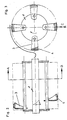
- Fig. 1 shows a side view of an inventive Roller mower, which carries screw-shaped cutting segments (2) on a shaft or a jacket (1). There is a gap (a) between the individual cutting segments (2), which overlap when viewed in the direction of travel, through which stones can pass in front of the cutting edge without long lateral transport.
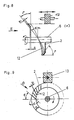
- Figures 2 to 4 show a further embodiment of a roller mower, which has a roller or a rotor (1) with pendulum-suspended, helical cutting sections (3), the edge zone (4) of which is toothed and inclined to the axial direction by the angle ⁇ .
- the pitch angle ⁇ of these cutting elements is advantageously chosen so that the mown material slides on the inclined element (3) and is thus axially conveyed. This means that a swath can be formed if the slope of the cutting sectors leads from both sides to the center.
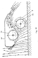
- FIG. 5 and 6 show an embodiment of the invention, in which the cutting element consist of plates (5) which are received by a shaft (6).
- the axis of rotation (6 ') of the shaft (6) is set to the direction of travel by an angle ⁇ .
- the edge of the disks is smooth and sharpened or has teeth (7) (see FIG. 6) that are cut or embossed.
- Such a cutting rotor can mow undershot or overhead. It is advantageous to fill the space between the disks with pipe pieces (8) which have a diameter such that their circumference corresponds approximately to the mean length of the stalk of the material to be mowed; this largely prevents winding around the rotor.
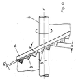
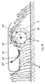
- Fig. 7 shows an embodiment in which the mowing rotor shown by the cutting circle (9) only in general is supported towards the floor by a slide rail (10).
- the front tip of the slide rail (10) extends into the area of the center of the axle, so that the continuous front edge supports the blade (11), which is cut off at a distance c from the rotor.
- FIG. 8 shows a side view
- FIG. 9 shows a view in the direction of arrow E in FIG. 8
- FIG. 10 shows an enlarged representation of advantageous tooth profiles of the cutting edges. They combine high stability of the cutting edges with the slight sharpening of the cutting edges in the machine.
- FIG. 8 shows half of a screw helix (2) which has an angle of inclination ⁇ with respect to the shaft (1).
- the edge zone (a) of the screw is inclined by the angle ⁇ with respect to the perpendicular to the shaft (6) of a roller (1), not shown. At about 30 °, the angle ca is kept so small that earth slides radially along and does not build up.
- the screw element (3) has a sheet thickness s.
- a corrugation (12) is cut or embossed in the edge zone (a) in such a way that a sheet thickness (s) of the edge zone (a) is maintained throughout, which contributes to its rigidity.
- the corrugation is preferably inclined with respect to a radial travel beam by the angle ⁇ (FIG.
- the corrugated surface is steamed with nitrates or case hardened.
- the unhardened area of the outer surface thus wears out faster; the teeth are thus self-sharpened.
- regrinding can also be carried out by moving a stone (13) back and forth parallel to the axis or by applying a corundum ledge.
- the outer surface (14) (dark in FIG. 10) is removed, the tooth shape being retained.
- the outer surface (14) of the cutting segment (3) thus forms part of the surface area of a roller, which is removed by grinding.
- FIG. 11 An alternative to the toothing of the inclined edge zone (a) is a wavy profile (15), as shown in FIG. 11. Due to the inclination of the round profile shaft by the angle with respect to the radial direction, a sharpened area b 'results as a cutting ruler.
- the outer surface (14 ') lies again on a roller shell and is thus to be sharpened in a simple manner by rotating the cutting element (3) by axially moving a grinding stone to and fro. Otherwise, the reference symbols in FIG. 11 have the same meaning as in FIGS. 8 to 10.
- toothing solutions described above in connection with the grinding option can also be used advantageously for large pitch angles ⁇ of continuous cutting edges, such as are used in reel mowers.
- Fig. 12 shows a side view of a reel mower with continuous cutting edges (2) which are arranged on a drum (not shown) with an axis (6).
- FIG. 13 shows a section at AB in FIG. 12.
- the sequence of the roundings (16) of the profiling of zone a of the cutting bar (3) is selected such that it is at the predetermined pitch angle ⁇ with the angle ⁇ ⁇ 90 ° runs out in relation to the direction of movement; the mown crop is pressed out of the curve (16) laterally; no crop sticks to the curves.
- Fig. 15 shows for known mowers the cutting energy required for cutting (dashed line) or the percentage of cut stalks or stalks (solid line) as a function of the angle of inclination ⁇ of the knife edge for a sharp edge and a blunt edge (according to Feller).
- Fig. 15 shows that a greater drop in the quality of the cut occurs with a blunt cutting edge even at a relatively small angle of inclination of approximately 30 °.
- FIG. 17 shows that the standing stalks in comma-shaped sections a1; a2; .... is knocked off.
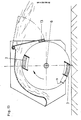
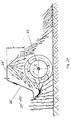
- FIG. 18 shows, as a further exemplary embodiment of the invention, a auger mower which has a cutting auger (1), a hood (20) and a cloth (21) which is arranged directly in front of the auger (1) and which is slightly on the forward-inclined blades (11 ) rests.
- the cloth (21) is attached to a rotatably mounted roller (21 ') so that the "free" length of the cloth is adjustable.
- the inclined straws only reach the cutting circle (9) of the mowing auger (1) near the ground, so that tapping from above is avoided.
- the close arrangement to the cutting roller also prevents mown material from being thrown against the standing crop, rather it is thrown upwards and backwards.
- the driver strips (22) support the rapid removal of the mown material from the cutting area.
- toothed strips (23) must be placed on it. Also an optional swiveling of the strips (22 ') up to the core for dosing the intensity of conveyance or preparation is provided.
- FIG. 19 shows a modification of the exemplary embodiment according to FIG. 18, in which the cloth is replaced by a driven roller (24) which actively conveys the clippings from the cutting area.
- Fig. 20 shows a further modification of the embodiment of FIG. 18, in which a raised hood (20 ') is arranged above the auger mower.
- the adjustment height (a) can be kept slightly less than the stalk length, so that the upper end of the stalks is moved backwards by the mowing drum (1); due to the sloping rear wall of the hood (20 ') there is a turning effect; the stalk ends are then essentially at the top of the swath.
- a tangled shelf or a shelf with the ears upwards can also be achieved.
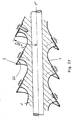
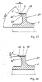
- Figure 21 shows the rotor of a auger mower, in which a thin continuous cutting edge (2) is screwed onto a worm-shaped base body (1), which includes an angle ⁇ ' ⁇ 60 ° to the axis (1'), so that in the area (26 ) Drain the soil and crop residue to the outside.
- the deposition of soil and straw particles would eventually lead to such a build-up that the cutting edge no longer has sufficient clearance for the cut; cutting becomes impossible.
- Figures 22 and 23 show further versions of the in 21 rotor shown:
- the base body 1 has a helical web (27) which carries the (cutting) band (2) on a cylindrical outer surface (28) which, when unwound, represents a straight strip (FIG. 22).
- the band (2) is supported against the collar (29) of the web (27) and can thus accommodate an axial cutting component.
- the flank (26) of the web (27) facing the cut side is in turn inclined to the axis (1 ') by about 60 °, so that no soil or parts of plants can build up.
- the opposite to the cutting edge (2 ') of the band (2) slightly set back, inclined flank (26) prevents that at the moment of cutting the stalks are pushed aside by the flank (26).
- the protrusion a of the cutting belt (2) is to be adapted to the stem diameter of the material to be mowed; it should be larger than the stem diameter so that the stalk does not run onto the flank (26) when cutting and is pressed to the side.
- Fig. 23 the cutting edge of the band (2) is serrated.
- the flank (26) of the web (27) opens out at the bottom of the teeth (28).
- the teeth (28) are set slightly outwards so that they can be ground in an S-shape on the line.
- the teeth can already be inclined on the loose, straight belt; it turns out that in the case of teeth that are small in relation to the screw diameter, it is possible for the tape to be "fully" placed on the web.
Landscapes
- Life Sciences & Earth Sciences (AREA)
- Environmental Sciences (AREA)
- Harvester Elements (AREA)
- Seal Device For Vehicle (AREA)
- Window Of Vehicle (AREA)
- Rear-View Mirror Devices That Are Mounted On The Exterior Of The Vehicle (AREA)
- Saccharide Compounds (AREA)
- Medicines That Contain Protein Lipid Enzymes And Other Medicines (AREA)
Applications Claiming Priority (6)
| Application Number | Priority Date | Filing Date | Title |
|---|---|---|---|
| DE3803725 | 1988-02-08 | ||
| DE19883803725 DE3803725A1 (de) | 1988-02-08 | 1988-02-08 | Walzenmaeher |
| DE19883819227 DE3819227A1 (de) | 1988-06-06 | 1988-06-06 | Schneckenmaeher |
| DE3819227 | 1988-06-06 | ||
| DE19883822161 DE3822161A1 (de) | 1988-06-06 | 1988-06-30 | Schneckenmaeher mit schneidband |
| DE3822161 | 1988-06-30 |
Publications (3)
| Publication Number | Publication Date |
|---|---|
| EP0328080A2 true EP0328080A2 (fr) | 1989-08-16 |
| EP0328080A3 EP0328080A3 (en) | 1989-11-02 |
| EP0328080B1 EP0328080B1 (fr) | 1995-11-15 |
Family
ID=27197157
Family Applications (1)
| Application Number | Title | Priority Date | Filing Date |
|---|---|---|---|
| EP89102169A Expired - Lifetime EP0328080B1 (fr) | 1988-02-08 | 1989-02-08 | Faucheuse hélicoidale |
Country Status (7)
| Country | Link |
|---|---|
| US (1) | US5027592A (fr) |
| EP (1) | EP0328080B1 (fr) |
| AT (1) | ATE130161T1 (fr) |
| DE (1) | DE58909490D1 (fr) |
| DK (1) | DK174630B1 (fr) |
| FI (1) | FI894755L (fr) |
| WO (1) | WO1989006898A1 (fr) |
Cited By (9)
| Publication number | Priority date | Publication date | Assignee | Title |
|---|---|---|---|---|
| EP0443079A3 (en) * | 1990-02-13 | 1995-01-11 | Lundahl Inc Ezra C | Improved crop processor |
| EP0800891A1 (fr) * | 1996-04-12 | 1997-10-15 | Maschinenfabrik Bermatingen GmbH & Co. | Procédé de fabrication des éléments de coupe |
| EP0861580A2 (fr) | 1997-02-27 | 1998-09-02 | Gerhard Dücker GmbH & Co. KG Landmaschinenfabrik | Appareil à faucher |
| EP0974255A1 (fr) * | 1998-07-20 | 2000-01-26 | Maschinenfabrik Bermatingen GmbH & Co. | Faucheuse hélicoidale |
| FR2784852A1 (fr) * | 1998-10-26 | 2000-04-28 | Emmanuelle Masson | Dispositif de coupe de vegetaux |
| WO2013027005A1 (fr) | 2011-08-25 | 2013-02-28 | Richard Campey Limited | Traitement de gazon |
| US11051449B2 (en) | 2018-03-29 | 2021-07-06 | Husqvarna Ab | Lawnmower cutting deck with angled cutter shafts |
| US12408588B2 (en) | 2021-06-17 | 2025-09-09 | Cnh Industrial America Llc | Cutting apparatus |
| US12501852B2 (en) | 2021-06-17 | 2025-12-23 | Cnh Industrial America Llc | Belt-type cutting system for cutting crops in a field |
Families Citing this family (11)
| Publication number | Priority date | Publication date | Assignee | Title |
|---|---|---|---|---|
| FR2741775B1 (fr) * | 1995-12-01 | 1998-01-23 | Bachmann Jacques | Rotor pour la coupe des vegetaux |
| DE10145170C1 (de) * | 2001-09-13 | 2003-05-22 | Mulag Fahrzeug Woessner | Messerwelle |
| SE524328C2 (sv) * | 2002-03-20 | 2004-07-27 | Mats Fischier I Baastad Ab | Cylinderenhet för gräsklippare och gräsklippare med dylik cylinderenhet |
| US7237374B2 (en) * | 2003-09-26 | 2007-07-03 | Scag Power Equipment, Inc. | Roller assembly for striping a lawn |
| US8109176B1 (en) * | 2010-04-14 | 2012-02-07 | Kooima Company | Cutting elements with serrated cutting edge |
| US12058964B2 (en) | 2017-10-27 | 2024-08-13 | Eteros Technologies Inc. | Plant trimming apparatus and methods |
| US10906047B2 (en) * | 2017-10-27 | 2021-02-02 | Eteros Technologies Inc. | Helical-bladed cutting reel |
| US10842080B2 (en) | 2017-10-27 | 2020-11-24 | Eteros Technologies Inc. | Plant trimming apparatus and methods |
| US11044852B2 (en) | 2019-05-21 | 2021-06-29 | Kooima Ag, Inc. | Agricultural knife with primary and secondary serrations |
| US12478037B2 (en) | 2021-09-17 | 2025-11-25 | Kooima Ag, Inc. | Bale ripper assembly for feed mixer apparatus |
| US12484485B1 (en) | 2022-11-02 | 2025-12-02 | Kooima Ag, Inc. | Cutting element with contoured surface |
Family Cites Families (14)
| Publication number | Priority date | Publication date | Assignee | Title |
|---|---|---|---|---|
| DE85193C (fr) * | ||||
| US2299384A (en) * | 1941-02-17 | 1942-10-20 | Clarence H Day | Lawn mower attachment |
| GB742595A (en) * | 1953-01-28 | 1955-12-30 | Alexander Shanks & Son Ltd | Improvements in or relating to machines of the rotating cylinder and knife type for cutting grass and other crops |
| US2904118A (en) * | 1958-07-10 | 1959-09-15 | Henry A Simpson | Cutting device |
| DE1147794B (de) * | 1959-04-09 | 1963-04-25 | John Alexander Chambliss | Vorrichtung zum Maehen von Gras, Unkraut, Strauchwerk oder Baeumchen |
| US3029583A (en) * | 1959-09-08 | 1962-04-17 | Patt Sylvester | Cutter bar and reel |
| US3073100A (en) * | 1960-08-15 | 1963-01-15 | Richard O Kingsley | Mower having helical cutter blade |
| NL6515224A (fr) * | 1965-11-24 | 1967-05-25 | ||
| NL6707676A (fr) * | 1967-06-02 | 1968-12-03 | ||
| US4109447A (en) * | 1976-11-11 | 1978-08-29 | Ferguson Hugo S | Mower of the cross-flow blower type with blades of opposite helix angle |
| US4719743A (en) * | 1981-11-16 | 1988-01-19 | Bokon William S | Nonhazardous mower |
| US4550554A (en) * | 1984-01-03 | 1985-11-05 | Ezra C. Lundahl, Inc. | Crop processor |
| DE3635925A1 (de) * | 1986-10-22 | 1988-04-28 | Wieneke Franz | Schneckenmaeher |
| DE3701668A1 (de) * | 1986-10-22 | 1988-08-04 | Wieneke Franz | Maehschnecke |
-
1989
- 1989-02-08 EP EP89102169A patent/EP0328080B1/fr not_active Expired - Lifetime
- 1989-02-08 DE DE58909490T patent/DE58909490D1/de not_active Expired - Fee Related
- 1989-02-08 FI FI894755A patent/FI894755L/fi not_active Application Discontinuation
- 1989-02-08 AT AT89102169T patent/ATE130161T1/de not_active IP Right Cessation
- 1989-02-08 WO PCT/DE1989/000077 patent/WO1989006898A1/fr not_active Ceased
- 1989-02-08 US US07/427,854 patent/US5027592A/en not_active Expired - Lifetime
- 1989-10-06 DK DK198904955A patent/DK174630B1/da not_active IP Right Cessation
Cited By (9)
| Publication number | Priority date | Publication date | Assignee | Title |
|---|---|---|---|---|
| EP0443079A3 (en) * | 1990-02-13 | 1995-01-11 | Lundahl Inc Ezra C | Improved crop processor |
| EP0800891A1 (fr) * | 1996-04-12 | 1997-10-15 | Maschinenfabrik Bermatingen GmbH & Co. | Procédé de fabrication des éléments de coupe |
| EP0861580A2 (fr) | 1997-02-27 | 1998-09-02 | Gerhard Dücker GmbH & Co. KG Landmaschinenfabrik | Appareil à faucher |
| EP0974255A1 (fr) * | 1998-07-20 | 2000-01-26 | Maschinenfabrik Bermatingen GmbH & Co. | Faucheuse hélicoidale |
| FR2784852A1 (fr) * | 1998-10-26 | 2000-04-28 | Emmanuelle Masson | Dispositif de coupe de vegetaux |
| WO2013027005A1 (fr) | 2011-08-25 | 2013-02-28 | Richard Campey Limited | Traitement de gazon |
| US11051449B2 (en) | 2018-03-29 | 2021-07-06 | Husqvarna Ab | Lawnmower cutting deck with angled cutter shafts |
| US12408588B2 (en) | 2021-06-17 | 2025-09-09 | Cnh Industrial America Llc | Cutting apparatus |
| US12501852B2 (en) | 2021-06-17 | 2025-12-23 | Cnh Industrial America Llc | Belt-type cutting system for cutting crops in a field |
Also Published As
| Publication number | Publication date |
|---|---|
| DK495589A (da) | 1989-10-06 |
| DK174630B1 (da) | 2003-07-28 |
| WO1989006898A1 (fr) | 1989-08-10 |
| ATE130161T1 (de) | 1995-12-15 |
| DE58909490D1 (de) | 1995-12-21 |
| FI894755A7 (fi) | 1989-10-06 |
| EP0328080B1 (fr) | 1995-11-15 |
| FI894755A0 (fi) | 1989-10-06 |
| DK495589D0 (da) | 1989-10-06 |
| EP0328080A3 (en) | 1989-11-02 |
| FI894755L (fi) | 1989-10-06 |
| US5027592A (en) | 1991-07-02 |
Similar Documents
| Publication | Publication Date | Title |
|---|---|---|
| EP0328080B1 (fr) | Faucheuse hélicoidale | |
| DE2645986C2 (de) | Rasenmäher | |
| EP2614698B1 (fr) | Faucheuse | |
| DE2424377A1 (de) | Scheibenmaeher | |
| DE2118914A1 (de) | Aus wenigstens einem Paar zusammenwirkender Mähkreisel bestehendes Mähwerk und nachgeschaltetem Quetschwalzenpaar bestehende Halmgutaufbereitungsmaschine | |
| EP0135724B1 (fr) | Récolte use à rangs multiples, notamment pour mais | |
| DE1296866B (de) | Rasenpflegegeraet | |
| DE3017856C2 (fr) | ||
| WO1988002983A2 (fr) | Moissonneuse a vis sans fin | |
| DE4109064A1 (de) | Maiserntegeraet | |
| DE202014104667U1 (de) | Schneidvorrichtung | |
| DE60100061T2 (de) | Mulchmäher | |
| EP0861580B1 (fr) | Appareil à faucher | |
| DE102011053352A1 (de) | Fahrgassenräumer | |
| EP3130214A1 (fr) | Faucheuse destinee a transporter et a cueillir des produits de recolte a tiges | |
| EP1181858A1 (fr) | Système de coupe et de déchiquetage pour tondeuse à gazon | |
| DE1657047A1 (de) | Maehmaschine | |
| DE2816967C2 (de) | Messer- bzw. Schneidbalken für Mähmaschinen | |
| DE102021129539A1 (de) | Scheiben-Mähkopf sowie Verfahren zum Abmähen von Bewuchs | |
| EP0664075B1 (fr) | Faucheuse à disques accouplée à un tracteur | |
| DE19706592C1 (de) | Rasenmäher | |
| DE2320126C2 (de) | Feldhäcksler | |
| DE10145170C1 (de) | Messerwelle | |
| EP3689130A1 (fr) | Enveloppe de rouleau pour un rouleau de conditionnement | |
| DE3819227A1 (de) | Schneckenmaeher |
Legal Events
| Date | Code | Title | Description |
|---|---|---|---|
| PUAI | Public reference made under article 153(3) epc to a published international application that has entered the european phase |
Free format text: ORIGINAL CODE: 0009012 |
|
| AK | Designated contracting states |
Kind code of ref document: A2 Designated state(s): AT BE CH DE ES FR GB GR IT LI LU NL SE |
|
| PUAL | Search report despatched |
Free format text: ORIGINAL CODE: 0009013 |
|
| AK | Designated contracting states |
Kind code of ref document: A3 Designated state(s): AT BE CH DE ES FR GB GR IT LI LU NL SE |
|
| 17P | Request for examination filed |
Effective date: 19900424 |
|
| 17Q | First examination report despatched |
Effective date: 19910416 |
|
| GRAA | (expected) grant |
Free format text: ORIGINAL CODE: 0009210 |
|
| AK | Designated contracting states |
Kind code of ref document: B1 Designated state(s): AT BE CH DE ES FR GB GR IT LI LU NL SE |
|
| PG25 | Lapsed in a contracting state [announced via postgrant information from national office to epo] |
Ref country code: ES Free format text: THE PATENT HAS BEEN ANNULLED BY A DECISION OF A NATIONAL AUTHORITY Effective date: 19951115 Ref country code: GR Free format text: LAPSE BECAUSE OF FAILURE TO SUBMIT A TRANSLATION OF THE DESCRIPTION OR TO PAY THE FEE WITHIN THE PRESCRIBED TIME-LIMIT Effective date: 19951115 |
|
| REF | Corresponds to: |
Ref document number: 130161 Country of ref document: AT Date of ref document: 19951215 Kind code of ref document: T |
|
| REF | Corresponds to: |
Ref document number: 58909490 Country of ref document: DE Date of ref document: 19951221 |
|
| GBT | Gb: translation of ep patent filed (gb section 77(6)(a)/1977) |
Effective date: 19960116 |
|
| ITF | It: translation for a ep patent filed | ||
| PG25 | Lapsed in a contracting state [announced via postgrant information from national office to epo] |
Ref country code: CH Free format text: LAPSE BECAUSE OF NON-PAYMENT OF DUE FEES Effective date: 19960228 Ref country code: LI Free format text: LAPSE BECAUSE OF NON-PAYMENT OF DUE FEES Effective date: 19960228 |
|
| PG25 | Lapsed in a contracting state [announced via postgrant information from national office to epo] |
Ref country code: LU Free format text: LAPSE BECAUSE OF NON-PAYMENT OF DUE FEES Effective date: 19960229 |
|
| ET | Fr: translation filed | ||
| PLBE | No opposition filed within time limit |
Free format text: ORIGINAL CODE: 0009261 |
|
| STAA | Information on the status of an ep patent application or granted ep patent |
Free format text: STATUS: NO OPPOSITION FILED WITHIN TIME LIMIT |
|
| REG | Reference to a national code |
Ref country code: CH Ref legal event code: PL |
|
| 26N | No opposition filed | ||
| NLS | Nl: assignments of ep-patents |
Owner name: MASCHINENFABRIK BERMATINGEN GMBH & CO. |
|
| REG | Reference to a national code |
Ref country code: GB Ref legal event code: 732E |
|
| REG | Reference to a national code |
Ref country code: FR Ref legal event code: TP |
|
| REG | Reference to a national code |
Ref country code: GB Ref legal event code: IF02 |
|
| PGFP | Annual fee paid to national office [announced via postgrant information from national office to epo] |
Ref country code: NL Payment date: 20050215 Year of fee payment: 17 |
|
| PGFP | Annual fee paid to national office [announced via postgrant information from national office to epo] |
Ref country code: BE Payment date: 20050218 Year of fee payment: 17 Ref country code: AT Payment date: 20050218 Year of fee payment: 17 |
|
| PGFP | Annual fee paid to national office [announced via postgrant information from national office to epo] |
Ref country code: SE Payment date: 20050221 Year of fee payment: 17 |
|
| PG25 | Lapsed in a contracting state [announced via postgrant information from national office to epo] |
Ref country code: AT Free format text: LAPSE BECAUSE OF NON-PAYMENT OF DUE FEES Effective date: 20060208 |
|
| PG25 | Lapsed in a contracting state [announced via postgrant information from national office to epo] |
Ref country code: SE Free format text: LAPSE BECAUSE OF NON-PAYMENT OF DUE FEES Effective date: 20060209 |
|
| PGFP | Annual fee paid to national office [announced via postgrant information from national office to epo] |
Ref country code: FR Payment date: 20060215 Year of fee payment: 18 |
|
| PGFP | Annual fee paid to national office [announced via postgrant information from national office to epo] |
Ref country code: GB Payment date: 20060221 Year of fee payment: 18 |
|
| PG25 | Lapsed in a contracting state [announced via postgrant information from national office to epo] |
Ref country code: BE Free format text: LAPSE BECAUSE OF NON-PAYMENT OF DUE FEES Effective date: 20060228 |
|
| PGFP | Annual fee paid to national office [announced via postgrant information from national office to epo] |
Ref country code: IT Payment date: 20060228 Year of fee payment: 18 |
|
| PGFP | Annual fee paid to national office [announced via postgrant information from national office to epo] |
Ref country code: DE Payment date: 20060405 Year of fee payment: 18 |
|
| PG25 | Lapsed in a contracting state [announced via postgrant information from national office to epo] |
Ref country code: NL Free format text: LAPSE BECAUSE OF NON-PAYMENT OF DUE FEES Effective date: 20060901 |
|
| EUG | Se: european patent has lapsed | ||
| NLV4 | Nl: lapsed or anulled due to non-payment of the annual fee |
Effective date: 20060901 |
|
| GBPC | Gb: european patent ceased through non-payment of renewal fee |
Effective date: 20070208 |
|
| REG | Reference to a national code |
Ref country code: FR Ref legal event code: ST Effective date: 20071030 |
|
| BERE | Be: lapsed |
Owner name: *MASCHINENFABRIK BERMATINGEN G.M.B.H. & CO. Effective date: 20060228 |
|
| PG25 | Lapsed in a contracting state [announced via postgrant information from national office to epo] |
Ref country code: DE Free format text: LAPSE BECAUSE OF NON-PAYMENT OF DUE FEES Effective date: 20070901 |
|
| PG25 | Lapsed in a contracting state [announced via postgrant information from national office to epo] |
Ref country code: FR Free format text: LAPSE BECAUSE OF NON-PAYMENT OF DUE FEES Effective date: 20070228 Ref country code: GB Free format text: LAPSE BECAUSE OF NON-PAYMENT OF DUE FEES Effective date: 20070208 |
|
| PG25 | Lapsed in a contracting state [announced via postgrant information from national office to epo] |
Ref country code: IT Free format text: LAPSE BECAUSE OF NON-PAYMENT OF DUE FEES Effective date: 20070208 |