EP0861580A2 - Appareil à faucher - Google Patents
Appareil à faucher Download PDFInfo
- Publication number
- EP0861580A2 EP0861580A2 EP98103189A EP98103189A EP0861580A2 EP 0861580 A2 EP0861580 A2 EP 0861580A2 EP 98103189 A EP98103189 A EP 98103189A EP 98103189 A EP98103189 A EP 98103189A EP 0861580 A2 EP0861580 A2 EP 0861580A2
- Authority
- EP
- European Patent Office
- Prior art keywords
- cutting
- mower according
- axis
- cutting pieces
- rotation
- Prior art date
- Legal status (The legal status is an assumption and is not a legal conclusion. Google has not performed a legal analysis and makes no representation as to the accuracy of the status listed.)
- Granted
Links
- 238000005520 cutting process Methods 0.000 claims abstract description 120
- 230000001154 acute effect Effects 0.000 claims abstract description 6
- 238000006073 displacement reaction Methods 0.000 claims description 7
- 230000000694 effects Effects 0.000 claims description 2
- 238000003801 milling Methods 0.000 description 3
- 238000012423 maintenance Methods 0.000 description 2
- 239000000463 material Substances 0.000 description 2
- 239000002689 soil Substances 0.000 description 2
- 239000000243 solution Substances 0.000 description 2
- 230000006735 deficit Effects 0.000 description 1
- 230000003628 erosive effect Effects 0.000 description 1
- 238000004519 manufacturing process Methods 0.000 description 1
- 238000000926 separation method Methods 0.000 description 1
- 239000010902 straw Substances 0.000 description 1
- 230000001502 supplementing effect Effects 0.000 description 1
- 230000007704 transition Effects 0.000 description 1
Images







Classifications
-
- A—HUMAN NECESSITIES
- A01—AGRICULTURE; FORESTRY; ANIMAL HUSBANDRY; HUNTING; TRAPPING; FISHING
- A01D—HARVESTING; MOWING
- A01D34/00—Mowers; Mowing apparatus of harvesters
- A01D34/01—Mowers; Mowing apparatus of harvesters characterised by features relating to the type of cutting apparatus
- A01D34/412—Mowers; Mowing apparatus of harvesters characterised by features relating to the type of cutting apparatus having rotating cutters
- A01D34/42—Mowers; Mowing apparatus of harvesters characterised by features relating to the type of cutting apparatus having rotating cutters having cutters rotating about a horizontal axis, e.g. cutting-cylinders
- A01D34/52—Cutting apparatus
- A01D34/53—Helically shaped cutting members
-
- A—HUMAN NECESSITIES
- A01—AGRICULTURE; FORESTRY; ANIMAL HUSBANDRY; HUNTING; TRAPPING; FISHING
- A01D—HARVESTING; MOWING
- A01D34/00—Mowers; Mowing apparatus of harvesters
- A01D34/01—Mowers; Mowing apparatus of harvesters characterised by features relating to the type of cutting apparatus
- A01D34/412—Mowers; Mowing apparatus of harvesters characterised by features relating to the type of cutting apparatus having rotating cutters
- A01D34/42—Mowers; Mowing apparatus of harvesters characterised by features relating to the type of cutting apparatus having rotating cutters having cutters rotating about a horizontal axis, e.g. cutting-cylinders
- A01D34/52—Cutting apparatus
Definitions
- the invention relates to a mower according to the preamble of the claim 1.
- EP 0 328 080 A2 discloses a mower of the type mentioned at the beginning which the cutting elements are provided with a cutting band, which as Strip is arranged on one side on the cutting elements. About subareas the cutting movement does not come to the rotation of the roller Use in the sense of a cutting contact with the blades to be mowed, because during this phase of movement, those carrying the cutting belt Cutting elements themselves are in contact with the straws, but not that Cutting tape, so that the overall cutting result only at a high Rotation speed of the roller with a corresponding material stress goes hand in hand, can be satisfactory.
- the invention is based on the problem of a mower of the type mentioned Art to improve in that it has a high cutting performance mechanical insensitivity and simplicity of maintenance are guaranteed at the same time.
- the arrangement of cutting pieces on the front and back of Supporting bodies can be ensured that during the entire rotation the support body around the axis of rotation of the roller a cutting process of clippings through the cutting pieces.
- the cutting pieces extend so over sub-segments of the outer area of the support body that this requirement due to an offset arrangement of the cutting pieces over the sub-segments Can be taken into account.
- the front and rear are preferably attached Cutting pieces against each other in a height offset with respect to the support body arranged, which not only gives the possibility of the projection the outer edge of the cutting pieces in the direction parallel to the axis of rotation during to let the company describe a circular path, what a uniform cutting of the clippings is essential, but also that at the transition point between the front and rear of a support body attached cutting body no impairment of the mowing result is present because of the height offset and the inclination of the supporting body on the roller, the outer edge of the front and rear cutting pieces Support body parallel to the axis of rotation of the roller and immediately one behind the other lie.
- the support body as a one-piece and at least partially elliptical Circumferential disc bodies in the form of swash plates are formed, which encompass the axis of rotation of the roller and opposite these are in an inclined position, this support body can be particularly inexpensive to manufacture and easy to assemble on the rotating drum.
- On such a one-piece support body are preferably two cutting pieces each arranged so that the assembly effort for changing the cutting pieces, which serve as wearing parts is kept low.
- the ellipse are offset against each other in such a way that one on one in Part arranged at an acute angle to the axis of rotation of the surface sector of a cutting body against one at an obtuse angle to Surface sector of the rotating axis of the arranged cutting body or part a cutting body parallel to the outside along this semiaxis is, this displacement against each other must go so far that the The outer circumference of the cutting pieces is always an equal distance from one another has floor level lying parallel to the axis of rotation, thereby a to ensure uniform cutting height.
- the supporting bodies can be provided with elongated holes, fastening means which penetrate the cutting pieces and the supporting body, can be adjusted along these slots. Easier to use and therefore for maintenance it is much cheaper if the support body are designed such that the cutting pieces only in a defined position can be mounted to the supporting body.
- the Carrier forms two similar semi-elliptical ring segments, the Outside outline a parallel offset corresponding to the height offset of the Has cutting body. These ring segments can then extend over their circumference distributed holes that exactly match the dimensions of the holes The cutting body match and the desired height offset without adjustment allow the cutting body to be adjusted on the supporting bodies. The order the holes in the ring segments follow the offset of the Half ellipses against each other.
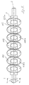
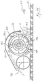
- the mower has one or more rollers 1, which by one Rotate axis of rotation 2 during operation of the mower, outside on the roller 1 support body 3,103 are arranged, which in turn in their Outside area facing away from the roller 1 with cutting pieces 4,4a, 4b, 4c, 104, 104a, 104b, 104c, 104d, 104e, 104f are provided.
- the supporting bodies 3 are staggered at an angle to the roller 1 and parallel to one another arranged (Fig. 4), the staggering is designed such that along an imaginary line 5 perpendicular to the axis of rotation an overlap of the Edge areas of different support body results, so that during rotation the roller 1 about the axis of rotation 2 of the outer contour of the entirety of the support body 3 describes a closed cylindrical surface, which the Longitudinal axis 2 of the roller 1 encloses without interruption.
- the roller 1 is mounted either in its outer areas via axle parts 6 and 7 and drivable, or the roller 1 can have several sections, which are separated from each other by bearings. That too is Number of rollers 1 variable.
- the support bodies 3, 103 can be individual, for example web-like or wedge-shaped trained holding elements to be formed over the circumference of the Roll 1 are individually welded and the cutting pieces 4,4a, 4b, 4c, Wear 104,104a, 104b, 104c, 104d, 104e, 104f.
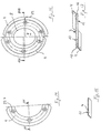
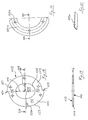
- the inner contour 8,108 the support body 3, 103 leaves an elliptical shaped recess 9, 109, whose small semi-axis 10,110 corresponds to the radius of the roller 1 and whose large semiaxis 11, 111 compared to this is so enlarged that after Sliding the support body 3,103 onto the roller 1 by contacting the entire inner circumference 8,108 to the outer circumference of the roller 1 the desired Inclination of the support body 3.103 is automatically secured and the supporting bodies 3, 103 in this inclined position with the roller 1 connected, in particular welded. This is the Assembly effort for attaching the support body 3,103 to the roller 1 very much low.
- the partial segments 14, 15 or 114, 115 as two symmetrical parts of a ring disk body 3,103 trained.
- Each of the subsegments 14, 15, 114, 115 is marked with a Cutting piece 4,4a, 4b, 4c, 104,104a, 104b, 104c, 104d, 104e, 104f, so that on each support body 3,103 two cutting pieces 4,4a, 4b, 4c, 104,104a, 104b, 104c, 104d, 104e, 104f are arranged.
- This number of two cutting pieces 4,4a, 4b, 4c, 104,104a, 104b, 104c, 104d, 104e, 104f per support body 3,103 represents a minimum number for the invention, a higher number of Cutting pieces 4,4a, 4b, 4c, 104,104a, 104b, 104c, 104d, 104e, 104f are possible.
- the support body 3, 103 has an acute angle on its front side 12, 112 surface sectors 17, 117 standing at the axis of rotation and at an obtuse angle to Surface sectors 18, 118 on axis of rotation; also has as a ring disc body trained support body 3,103 on its back 113 acute-angled surface sectors 119 standing to the axis of rotation and obtuse to Surface sectors 120 standing on the axis of rotation.
- the height offset between the cutting pieces assigned to a supporting body 3, 103 4,4a, 4b, 4c, 104,104a, 104b, 104c, 104d, 104e, 104f is achieved in that Cutting pieces 4,4a, 4b, 4c, 104,104a, 104b, 104c, 104d, 104e, 104f or parts of cutting pieces 4,4a, 4b, 4c, 104,104a, 104b, 104c, 104d, 104e, 104f, which on surface sectors 17, 117 of the front standing at an acute angle to the axis of rotation 2 12,112 or 19,119 of the rear 13,113 of the support body 3,103 arranged are, along the major semi-axis of the ellipse, that of the supporting body 3,103 is formed, are shifted outwards compared to cutting pieces 4,4a, 4b, 4c, 104,104a, 104b, 104c, 104d, 104e, 104f or their parts, which extend
- cutting pieces are only located over one of these acute-angled surface sectors 17,19 and 117,119 extend, these cutting pieces are a total shifted to the outside.
- the cutting pieces 4,4a, 4b, 4c, 104,104a, 104b, 104c, 104d, 104e, 104f both via acute-angled 17.19 and 117.119 respectively obtuse-angled surface sectors 18.20 and 118.120.
- This height offset goes so far that the outer circumference of the cutting pieces 4,4a, 4b, 4c, 104,104a, 104b, 104c, 104d, 104e, 104f always the same Distance to a floor plane 21 lying parallel to the axis of rotation 2 having.
- Inclined position of the support body 3.103 can be the same radial distance of the cutting pieces 4,4a, 4b, 4c, 104,104a, 104b, 104c, 104d, 104e, 104f from the Ensure axis of rotation 2.
- 14.15 is on each ring segment or 114, 115 a cutting piece 4,4a, 4b, 4c, 104,104a, 104b, 104c, 104d, 104e, 104f.
- the cutting pieces must be reduced accordingly and can only extend over a smaller part of the circumference. Either a serial attachment of several smaller cutting pieces on one of the Pages 12, 112 and 13, 113 of the support body 3, 103 are made possible as an additional alternation between the front and back 12, 13 or 112.113.
- the swash plates can be designed Support body 3,103 during the entire rotational movement of the Roller 1 perform a cutting operation, the overlap of the Swash plates 3,103 along line 5 each area of the area to be mowed or to be milled bottom 21 at least twice from differently oriented Cutting pieces 4,4a, 4b, 4c, 104,104a, 104b, 104c, 104d, 104e, 104f one or more support body 3,103 is contacted.
- the cutting or milling effect is significantly improved over conventional arrangements because the alternate attachment of the cutting pieces 4,4a, 4b, 4c, 104, 104a, 104b, 104c, 104d, 104e, 104f on the supporting bodies 3, 103 the cutting action the swashplate enlarged significantly per revolution. So that at constant speed achieved a significantly improved cutting result or to achieve the same cutting result The speed of the roller 1 can be significantly reduced.
- both in a cutting erosion of stalks can also consist in milling a top layer of soil -
- the roller 1 is perpendicular to its axis of rotation 2 above the floor level 21 pulled.
- a support roller 30 can be arranged behind the roller 1 be by means of the distance of the outer edge of the cutting pieces 4,4a, 4b, 4c, 104,104a, 104b, 104c, 104d, 104e, 104f with respect to the floor level 21 is adjustable.
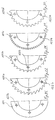
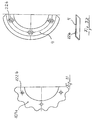
- the cutting pieces 4,4a, 4b, 4c, 104,104a, 104b, 104c, 104d, 104e, 104f they can, as in FIGS. 26 to 31 shown to be formed as smooth ring segments, the outer edge can either be smooth or jagged in various subtleties Can have a contour (Fig. 27 to Fig. 29) or is corrugated (Fig. 30, Fig. 31).
- the outer edge of the cutting pieces 4,4a, 4b, 4c and 104,104a, 104b, 104c, 104d, 104e, 104f also sideways be chamfered, again with the most varied forms a smooth 4a, wavy 104e, serrated 4b or sawtooth-like 4c, 104f shaped profile.
Landscapes
- Life Sciences & Earth Sciences (AREA)
- Environmental Sciences (AREA)
- Harvester Elements (AREA)
- Beans For Foods Or Fodder (AREA)
- Tea And Coffee (AREA)
- Confectionery (AREA)
Applications Claiming Priority (2)
| Application Number | Priority Date | Filing Date | Title |
|---|---|---|---|
| DE29703498U DE29703498U1 (de) | 1997-02-27 | 1997-02-27 | Mähgerät |
| DE29703498U | 1997-02-27 |
Publications (3)
| Publication Number | Publication Date |
|---|---|
| EP0861580A2 true EP0861580A2 (fr) | 1998-09-02 |
| EP0861580A3 EP0861580A3 (fr) | 2003-01-02 |
| EP0861580B1 EP0861580B1 (fr) | 2004-12-15 |
Family
ID=8036620
Family Applications (1)
| Application Number | Title | Priority Date | Filing Date |
|---|---|---|---|
| EP98103189A Expired - Lifetime EP0861580B1 (fr) | 1997-02-27 | 1998-02-24 | Appareil à faucher |
Country Status (5)
| Country | Link |
|---|---|
| EP (1) | EP0861580B1 (fr) |
| AT (1) | ATE284607T1 (fr) |
| DE (2) | DE29703498U1 (fr) |
| DK (1) | DK0861580T3 (fr) |
| PL (1) | PL185767B1 (fr) |
Families Citing this family (7)
| Publication number | Priority date | Publication date | Assignee | Title |
|---|---|---|---|---|
| DE29716916U1 (de) | 1997-09-20 | 1998-03-26 | Gerhard Dücker GmbH & Co. KG Landmaschinenfabrik, 48703 Stadtlohn | Mähgerät |
| DE19832525C1 (de) * | 1998-07-20 | 2000-02-17 | Bermatingen Maschf | Schneckenmäher |
| DE10145170C1 (de) * | 2001-09-13 | 2003-05-22 | Mulag Fahrzeug Woessner | Messerwelle |
| DE10234814A1 (de) * | 2002-07-31 | 2004-02-19 | Walter Kolb | Schneidvorrichtung für Pflanzen |
| FR2916936B1 (fr) * | 2007-06-06 | 2009-08-21 | Campes Jacques Villa | Dispositif pour couper la vegetation. |
| DE102017114132A1 (de) | 2017-06-26 | 2018-12-27 | Wiedenmann Gmbh | Bodenbearbeitungswerkzeugelement, Bodenbearbeitungswerkzeugscheibe, Satz von derartigen Elementen, Bodenbearbeitungsrotor und Bodenbearbeitungsgerät |
| DE202018107424U1 (de) * | 2018-12-24 | 2019-02-14 | Klaus Wallner | Schneidmesser |
Citations (1)
| Publication number | Priority date | Publication date | Assignee | Title |
|---|---|---|---|---|
| EP0328080A2 (fr) | 1988-02-08 | 1989-08-16 | Franz Prof. Dr.-Ing. Wieneke | Faucheuse hélicoidale |
Family Cites Families (5)
| Publication number | Priority date | Publication date | Assignee | Title |
|---|---|---|---|---|
| US3514934A (en) * | 1967-04-10 | 1970-06-02 | Samuel G Cassady | Cutting assembly |
| US3690047A (en) * | 1971-09-21 | 1972-09-12 | Roy M Thoen | Combination lawn mowing and snow throwing machine |
| US4267690A (en) * | 1980-04-14 | 1981-05-19 | Pike Carl A | Disc reel mower and method and means of manufacturing the same |
| EP0116054A1 (fr) * | 1982-07-28 | 1984-08-22 | BYRD, George Malcolm | Ameliorations relatives a des agitateurs rotatifs |
| EP0238827A1 (fr) * | 1986-02-17 | 1987-09-30 | Klöckner-Humboldt-Deutz Aktiengesellschaft | Dispositif de coupe pour faucheuse |
-
1997
- 1997-02-27 DE DE29703498U patent/DE29703498U1/de not_active Expired - Lifetime
-
1998
- 1998-02-24 AT AT98103189T patent/ATE284607T1/de active
- 1998-02-24 DK DK98103189T patent/DK0861580T3/da active
- 1998-02-24 EP EP98103189A patent/EP0861580B1/fr not_active Expired - Lifetime
- 1998-02-24 DE DE59812373T patent/DE59812373D1/de not_active Expired - Lifetime
- 1998-02-25 PL PL98325003A patent/PL185767B1/pl unknown
Patent Citations (1)
| Publication number | Priority date | Publication date | Assignee | Title |
|---|---|---|---|---|
| EP0328080A2 (fr) | 1988-02-08 | 1989-08-16 | Franz Prof. Dr.-Ing. Wieneke | Faucheuse hélicoidale |
Also Published As
| Publication number | Publication date |
|---|---|
| EP0861580A3 (fr) | 2003-01-02 |
| DE29703498U1 (de) | 1997-10-09 |
| EP0861580B1 (fr) | 2004-12-15 |
| DE59812373D1 (de) | 2005-01-20 |
| DK0861580T3 (da) | 2005-02-21 |
| ATE284607T1 (de) | 2005-01-15 |
| PL185767B1 (pl) | 2003-07-31 |
| PL325003A1 (en) | 1998-08-31 |
Similar Documents
| Publication | Publication Date | Title |
|---|---|---|
| DE1782740C2 (de) | Mähmaschine mit einem in Arbeitslage dicht über den Boden geführten, langgestreckten, flachen, kastenförmigen Tragkörper | |
| EP0508189B1 (fr) | Machine pour faucher et hacher le mais et les plantes à tige similaires | |
| DE2556553C2 (fr) | ||
| DE2505679A1 (de) | Umlaufende maehvorrichtung | |
| DE1970258U (de) | Maehmaschine. | |
| DE2641370C2 (de) | Gerät zum Vernichten von Mikrofilmen und dergleichen | |
| EP0328080B1 (fr) | Faucheuse hélicoidale | |
| DE2118914A1 (de) | Aus wenigstens einem Paar zusammenwirkender Mähkreisel bestehendes Mähwerk und nachgeschaltetem Quetschwalzenpaar bestehende Halmgutaufbereitungsmaschine | |
| DE2908948C2 (fr) | ||
| EP0135724B1 (fr) | Récolte use à rangs multiples, notamment pour mais | |
| DE2555580A1 (de) | Schneidmechanismus fuer rasenmaeher | |
| EP0423626B1 (fr) | Dispositif à ramasser pour récolter des céréales, en particulier de mais | |
| DE3017856C2 (fr) | ||
| EP0861580B1 (fr) | Appareil à faucher | |
| EP0358045B1 (fr) | Faucheuse | |
| EP0172160B1 (fr) | Faucheuse ou hacheuse | |
| DD229942A5 (de) | Verfahren und vorrichtung zur zerkleinerung von pflanzengut | |
| DE4202865C2 (de) | Rasenmäher | |
| EP0782380B1 (fr) | Faucheuse | |
| EP0093940B1 (fr) | Contre-lame pour une tête, notamment pour machines de récolte | |
| DE2703301A1 (de) | Maehmaschine | |
| DE1657047C3 (de) | Mähmaschine mit um zueinander parallele Achsen gegenläufig umlaufenden Schnittwerkzeugen | |
| DE10234814A1 (de) | Schneidvorrichtung für Pflanzen | |
| EP0238827A1 (fr) | Dispositif de coupe pour faucheuse | |
| DE3826984A1 (de) | Maehscheibe |
Legal Events
| Date | Code | Title | Description |
|---|---|---|---|
| PUAI | Public reference made under article 153(3) epc to a published international application that has entered the european phase |
Free format text: ORIGINAL CODE: 0009012 |
|
| AK | Designated contracting states |
Kind code of ref document: A2 Designated state(s): AT BE CH DE DK ES FI FR GB GR IE IT LI LU MC NL PT SE |
|
| AX | Request for extension of the european patent |
Free format text: AL;LT;LV;MK;RO;SI |
|
| PUAL | Search report despatched |
Free format text: ORIGINAL CODE: 0009013 |
|
| AK | Designated contracting states |
Kind code of ref document: A3 Designated state(s): AT BE CH DE DK ES FI FR GB GR IE IT LI LU MC NL PT SE |
|
| AX | Request for extension of the european patent |
Free format text: AL;LT;LV;MK;RO;SI |
|
| 17P | Request for examination filed |
Effective date: 20030627 |
|
| AKX | Designation fees paid |
Designated state(s): AT BE CH DE DK LI NL |
|
| 17Q | First examination report despatched |
Effective date: 20031104 |
|
| GRAP | Despatch of communication of intention to grant a patent |
Free format text: ORIGINAL CODE: EPIDOSNIGR1 |
|
| GRAS | Grant fee paid |
Free format text: ORIGINAL CODE: EPIDOSNIGR3 |
|
| GRAA | (expected) grant |
Free format text: ORIGINAL CODE: 0009210 |
|
| AK | Designated contracting states |
Kind code of ref document: B1 Designated state(s): AT BE CH DE DK LI NL |
|
| REG | Reference to a national code |
Ref country code: CH Ref legal event code: EP |
|
| REG | Reference to a national code |
Ref country code: CH Ref legal event code: NV Representative=s name: PATENTANWAELTE FELDMANN & PARTNER AG |
|
| REG | Reference to a national code |
Ref country code: IE Ref legal event code: FG4D Free format text: GERMAN |
|
| REF | Corresponds to: |
Ref document number: 59812373 Country of ref document: DE Date of ref document: 20050120 Kind code of ref document: P Owner name: KIVIVASARA, ALLI ADAM |
|
| REG | Reference to a national code |
Ref country code: DK Ref legal event code: T3 |
|
| PLBE | No opposition filed within time limit |
Free format text: ORIGINAL CODE: 0009261 |
|
| STAA | Information on the status of an ep patent application or granted ep patent |
Free format text: STATUS: NO OPPOSITION FILED WITHIN TIME LIMIT |
|
| 26N | No opposition filed |
Effective date: 20050916 |
|
| REG | Reference to a national code |
Ref country code: CH Ref legal event code: PFA Owner name: GERHARD DUECKER GMBH & CO. KG LANDMASCHINENFABRIK Free format text: GERHARD DUECKER GMBH & CO. KG LANDMASCHINENFABRIK#WENDFELD 9#48703 STADTLOHN (DE) -TRANSFER TO- GERHARD DUECKER GMBH & CO. KG LANDMASCHINENFABRIK#WENDFELD 9#48703 STADTLOHN (DE) |
|
| PGFP | Annual fee paid to national office [announced via postgrant information from national office to epo] |
Ref country code: DE Payment date: 20161114 Year of fee payment: 20 |
|
| PGFP | Annual fee paid to national office [announced via postgrant information from national office to epo] |
Ref country code: BE Payment date: 20170127 Year of fee payment: 20 Ref country code: AT Payment date: 20170223 Year of fee payment: 20 Ref country code: NL Payment date: 20170224 Year of fee payment: 20 Ref country code: DK Payment date: 20170125 Year of fee payment: 20 |
|
| PGFP | Annual fee paid to national office [announced via postgrant information from national office to epo] |
Ref country code: CH Payment date: 20170529 Year of fee payment: 20 |
|
| REG | Reference to a national code |
Ref country code: DE Ref legal event code: R071 Ref document number: 59812373 Country of ref document: DE |
|
| REG | Reference to a national code |
Ref country code: DK Ref legal event code: EUP Effective date: 20180224 |
|
| REG | Reference to a national code |
Ref country code: CH Ref legal event code: PL Ref country code: NL Ref legal event code: MK Effective date: 20180223 |
|
| REG | Reference to a national code |
Ref country code: BE Ref legal event code: MK Effective date: 20180224 |
|
| REG | Reference to a national code |
Ref country code: AT Ref legal event code: MK07 Ref document number: 284607 Country of ref document: AT Kind code of ref document: T Effective date: 20180224 |