EP0328092A1 - Appareil de cuisson - Google Patents
Appareil de cuisson Download PDFInfo
- Publication number
- EP0328092A1 EP0328092A1 EP89102216A EP89102216A EP0328092A1 EP 0328092 A1 EP0328092 A1 EP 0328092A1 EP 89102216 A EP89102216 A EP 89102216A EP 89102216 A EP89102216 A EP 89102216A EP 0328092 A1 EP0328092 A1 EP 0328092A1
- Authority
- EP
- European Patent Office
- Prior art keywords
- metal detector
- cooking appliance
- appliance according
- cooking
- following
- Prior art date
- Legal status (The legal status is an assumption and is not a legal conclusion. Google has not performed a legal analysis and makes no representation as to the accuracy of the status listed.)
- Withdrawn
Links
- 238000010411 cooking Methods 0.000 title claims abstract description 42
- 229910052751 metal Inorganic materials 0.000 claims abstract description 47
- 239000002184 metal Substances 0.000 claims abstract description 47
- 238000010438 heat treatment Methods 0.000 claims abstract description 39
- 239000000853 adhesive Substances 0.000 claims description 3
- 230000001070 adhesive effect Effects 0.000 claims description 3
- 238000009413 insulation Methods 0.000 claims description 3
- 229910000831 Steel Inorganic materials 0.000 claims description 2
- 229910052782 aluminium Inorganic materials 0.000 claims description 2
- XAGFODPZIPBFFR-UHFFFAOYSA-N aluminium Chemical compound [Al] XAGFODPZIPBFFR-UHFFFAOYSA-N 0.000 claims description 2
- 238000001514 detection method Methods 0.000 claims description 2
- 239000000696 magnetic material Substances 0.000 claims description 2
- 239000010959 steel Substances 0.000 claims description 2
- 238000004804 winding Methods 0.000 claims description 2
- 229910000859 α-Fe Inorganic materials 0.000 claims description 2
- 229910052759 nickel Inorganic materials 0.000 claims 1
- PXHVJJICTQNCMI-UHFFFAOYSA-N nickel Substances [Ni] PXHVJJICTQNCMI-UHFFFAOYSA-N 0.000 claims 1
- 239000011810 insulating material Substances 0.000 abstract description 6
- 230000004913 activation Effects 0.000 description 2
- 230000002411 adverse Effects 0.000 description 1
- VNNRSPGTAMTISX-UHFFFAOYSA-N chromium nickel Chemical compound [Cr].[Ni] VNNRSPGTAMTISX-UHFFFAOYSA-N 0.000 description 1
- 238000010276 construction Methods 0.000 description 1
- 238000005485 electric heating Methods 0.000 description 1
- 230000005672 electromagnetic field Effects 0.000 description 1
- 239000002241 glass-ceramic Substances 0.000 description 1
- 230000002452 interceptive effect Effects 0.000 description 1
- 230000007257 malfunction Effects 0.000 description 1
- 238000005259 measurement Methods 0.000 description 1
- 238000000034 method Methods 0.000 description 1
- 230000035945 sensitivity Effects 0.000 description 1
Images
Classifications
-
- F—MECHANICAL ENGINEERING; LIGHTING; HEATING; WEAPONS; BLASTING
- F24—HEATING; RANGES; VENTILATING
- F24C—DOMESTIC STOVES OR RANGES ; DETAILS OF DOMESTIC STOVES OR RANGES, OF GENERAL APPLICATION
- F24C15/00—Details
- F24C15/10—Tops, e.g. hot plates; Rings
- F24C15/102—Tops, e.g. hot plates; Rings electrically heated
- F24C15/105—Constructive details concerning the regulation of the temperature
-
- H—ELECTRICITY
- H05—ELECTRIC TECHNIQUES NOT OTHERWISE PROVIDED FOR
- H05B—ELECTRIC HEATING; ELECTRIC LIGHT SOURCES NOT OTHERWISE PROVIDED FOR; CIRCUIT ARRANGEMENTS FOR ELECTRIC LIGHT SOURCES, IN GENERAL
- H05B3/00—Ohmic-resistance heating
- H05B3/68—Heating arrangements specially adapted for cooking plates or analogous hot-plates
- H05B3/74—Non-metallic plates, e.g. vitroceramic, ceramic or glassceramic hobs, also including power or control circuits
- H05B3/746—Protection, e.g. overheat cutoff, hot plate indicator
-
- H—ELECTRICITY
- H05—ELECTRIC TECHNIQUES NOT OTHERWISE PROVIDED FOR
- H05B—ELECTRIC HEATING; ELECTRIC LIGHT SOURCES NOT OTHERWISE PROVIDED FOR; CIRCUIT ARRANGEMENTS FOR ELECTRIC LIGHT SOURCES, IN GENERAL
- H05B2213/00—Aspects relating both to resistive heating and to induction heating, covered by H05B3/00 and H05B6/00
- H05B2213/05—Heating plates with pan detection means
Definitions
- the invention relates to a cooking appliance according to the preamble of the first claim.
- a metal detector is arranged as a sensor for detecting the presence or absence of a metal vessel under a cooking surface of a heating element designed as a closed hob.
- the sensor is connected to a control element which, in the presence of a metal vessel in the cooking area, switches a circuit of the heating element so that the heating element is only energized. It can be seen that external interference can adversely affect the switching behavior in practical operation.
- the invention has for its object to take measures in a cooking appliance according to the preamble of the first claim, by means of which disruptive influences by external, in particular electromagnetic, fields are reduced or avoided entirely.
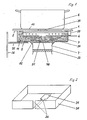
- a cooking device shown schematically in a detail has a non-metallic, in particular glass-ceramic cooking surface 1, which is designed without openings or the like.
- a non-magnetic insulating material plate 3 running parallel thereto, the outer edges of which are drawn up in a pot shape up to the underside 2 and which, moreover, carries an electric heating coil 4 on its inner top side 5.
- the area under the heating element 4 defines a cooking area within the cooking surface 1, which in the example shown is approximately identical to the base 10 of a metallic vessel 6.
- the presence or absence of this vessel 6 is determined by means of a metal detector 7, which is arranged adjacent to the underside 11 of the insulating material plate 3, the active side of which points towards the cooking area and which is also arranged outside an area covered by the heating element 4.
- the metal detector 7 acts with its sensor field right into the cooking area and influences a control element, not shown, in such a way that when the vessel 6 is present, the heating element 4 is switched on and the vessel 6 is heated when the switch-on state is otherwise prepared becomes. If the vessel is missing, the circuit of the heating element 4 is interrupted via the metal detector 7 while the switch-on state is still prepared.
- the entire insulating material plate 3 with the raised outer edges and the heating element 4 is arranged in an adapted, pot-shaped shielding shell 30, which is located in the active area of the Metal detector 7 has an adapted cutout 31. Through this cutout 31, the sensor field of the metal detector 7 passes toward the cooking area through the insulating plate 3 and through the cooking surface 1 into the area on which the vessel 6 is to be placed and can be detected.
- the shielding shell 30 is preferably made of chromium-nickel steel or aluminum sheet or a non-magnetic material.
- the metal detector 7 is fixed to the shielding shell 30 by means of a temperature-resistant, permanently elastic adhesive 32, so that expansions cannot lead to mechanical stresses which result in incorrect measurements.
- the metal sensor 7 is thermally decoupled from the insulating plate 3 by the air gap formed in the cutout 31 and by the adhesive 32, which in turn forms high-quality thermal insulation with a coefficient of thermal conductivity of approximately 0.02 W / mk in order to determine the temperature at the metal detector 7, which emanates from the heating element 4, in order to avoid malfunctions as low as possible.
- the metal detector 7 has a shell core made of a ferrite with a high Curie temperature and a winding made of a wire with a high-temperature-resistant insulation.
- the metal detector 7 can be arranged in the air stream of a blower or a convection shaft in order to be able to keep its temperature as constant as possible.
- the air flow can be controlled as a function of the temperature of the metal sensor 7.
- a heating resistor 33 is assigned to the metal detector, which thermostatically controlled keeps the temperature of the metal sensor 7 largely constant.
- the shielding shell 30 is provided with at least one slot 34 in order to reduce interfering ring currents which can arise in the shielding shell 30 from the alternating electromagnetic field emanating from the active area of the metal detector 7.
- This slot 34 preferably extends from the cutout 31 in the radial direction on one side through the raised edge (FIG. 2). It is also possible to have a plurality of S, only partial lengths of the shielding shell 30 Slots are provided. The metal detector 7 is less electrically damped by the slitting and therefore its effectiveness is increased.
- the shielding shells 30 are expediently electrically insulated from one another and from a common, only indicated, support frame 35 in order to avoid mutual interference. This measure is expediently also applied between the support frame 35 and a device housing 36, which is also only indicated.
- the metal detector is only activated briefly, or during the period in which the switching on of a heating device is possible or prepared, by manually operated switching devices, or is interrogated electrically.
- the circuit of the heating element 3 is interrupted in any case during the brief activation or query of the metal detector 7.
- the magnetic field of the heating element 3 can then cause no control errors.
- the pulse operation of the metal detector 7 is particularly suitable in the case of a plurality of heating devices because all metal detectors can then be activated and / or queried in succession with a control element as to whether or not a metal vessel 6 is placed on the associated cooking area.
- Each heating device is preferably connected to an energy controller 39 or temperature limiter, which interrupts the circuit of the respectively assigned heating element 3 when predetermined operating conditions are reached. These interruptions are preferably communicated to the control element, which then activates and / or queries the associated metal detector 7. This saves interruptions in the circuit and avoids additional radio interference.
- the metal detector (s) 7 is operated in pulsed mode, a delay in the switching process may occur when the vessel 6 is placed on and removed, but the pulse frequency can be chosen so high that no noticeable disadvantages arise. Otherwise, the interruption of the circuit for the heating element 3 is, for example, 0.5 seconds.
- the area within which the metal detector 7 detects a vessel 6 placed thereon is designated 37 in FIG. 1 and is in alignment with the cutout 31 and the area 38 on the upper side 5 of the insulating material plate 3 that is free of turns of the heating element 4.
Landscapes
- Engineering & Computer Science (AREA)
- Chemical & Material Sciences (AREA)
- Ceramic Engineering (AREA)
- Combustion & Propulsion (AREA)
- Mechanical Engineering (AREA)
- General Engineering & Computer Science (AREA)
- Electric Stoves And Ranges (AREA)
- Cookers (AREA)
Applications Claiming Priority (2)
| Application Number | Priority Date | Filing Date | Title |
|---|---|---|---|
| DE19883804170 DE3804170A1 (de) | 1987-04-06 | 1988-02-11 | Kochgeraet |
| DE3804170 | 1988-02-11 |
Publications (1)
| Publication Number | Publication Date |
|---|---|
| EP0328092A1 true EP0328092A1 (fr) | 1989-08-16 |
Family
ID=6347146
Family Applications (1)
| Application Number | Title | Priority Date | Filing Date |
|---|---|---|---|
| EP89102216A Withdrawn EP0328092A1 (fr) | 1988-02-11 | 1989-02-09 | Appareil de cuisson |
Country Status (1)
| Country | Link |
|---|---|
| EP (1) | EP0328092A1 (fr) |
Cited By (1)
| Publication number | Priority date | Publication date | Assignee | Title |
|---|---|---|---|---|
| EP0429120A3 (en) * | 1989-11-17 | 1991-09-11 | Whirlpool International B.V. | Device for detecting the presence of a food cooking container on a cooking hob |
Citations (3)
| Publication number | Priority date | Publication date | Assignee | Title |
|---|---|---|---|---|
| FR1340411A (fr) * | 1962-11-14 | 1963-10-18 | Plaques chauffantes | |
| US3796850A (en) * | 1973-05-31 | 1974-03-12 | Westinghouse Electric Corp | Pan detector for induction heating cooking unit |
| FR2259571A1 (fr) * | 1974-02-04 | 1975-08-29 | Matsushita Electric Industrial Co Ltd |
-
1989
- 1989-02-09 EP EP89102216A patent/EP0328092A1/fr not_active Withdrawn
Patent Citations (3)
| Publication number | Priority date | Publication date | Assignee | Title |
|---|---|---|---|---|
| FR1340411A (fr) * | 1962-11-14 | 1963-10-18 | Plaques chauffantes | |
| US3796850A (en) * | 1973-05-31 | 1974-03-12 | Westinghouse Electric Corp | Pan detector for induction heating cooking unit |
| FR2259571A1 (fr) * | 1974-02-04 | 1975-08-29 | Matsushita Electric Industrial Co Ltd |
Cited By (1)
| Publication number | Priority date | Publication date | Assignee | Title |
|---|---|---|---|---|
| EP0429120A3 (en) * | 1989-11-17 | 1991-09-11 | Whirlpool International B.V. | Device for detecting the presence of a food cooking container on a cooking hob |
Similar Documents
| Publication | Publication Date | Title |
|---|---|---|
| EP0442275B1 (fr) | Dispositif ou détection d'un récipient placé dans une zone de chauffage d'un appareil de cuisson ou de chauffage | |
| EP0471171B1 (fr) | Dispositif pour la régulation et le limitation de la puissance d'une surface de chauffage en céramique ou un matériau similaire | |
| EP0438656B1 (fr) | Plaque de cuisson | |
| EP0788293B1 (fr) | Radiateur électrique avec un capteur actif pour la détection d'un récipient de cuisson | |
| DE60028485T2 (de) | Objekterfassungssystem, welches zum Beispiel die Anwesenheit eines metallischen Kochgerätes auf einer nichtmetallischen Kochoberfläche erfasst | |
| DE69100010T2 (de) | Vorrichtung zur heizstellenregelung bei einem kochgeraet durch sensortasten. | |
| EP0467134B1 (fr) | Procédé et appareil pour indiquer un état de charge anormal thermique d'un panneau chauffé | |
| DE69320667T2 (de) | Glaskeramik-Kochmulde mit mehreren Heizzonen | |
| DE3744372C2 (de) | Leistungssteuerungsverfahren zum Schutz von Glaskeramikkochflächen | |
| DE69507932T2 (de) | Induktionsheizvorrichtung für Behälter und Steuerungsverfahren dafür | |
| DE3703768C2 (fr) | ||
| EP3518618B1 (fr) | Plaque de cuisson pourvue d'au moins deux zones chauffantes | |
| DE3505233C1 (de) | Anordnung zum Steuern und Regeln der Heizleistung in der Aufheizphase eines Kochgefaesses | |
| EP0722261A1 (fr) | Cuisinière avec plaque à rayonnement et plaque à induction | |
| EP0116861B2 (fr) | Corps de chauffe radiant électrique pour le chauffage de plaques de cuisson ou de plaques chaudes, en particulier plaques en vitro-céramique | |
| EP0374868A1 (fr) | Plaque de cuisson | |
| DE10035745A1 (de) | Temperaturerfassungseinrichtung für einen elektrischen Strahlungsheizkörper | |
| DE3327622A1 (de) | Elektrische heizplatte fuer ein glaskeramik-kochfeld | |
| DE3711589C2 (fr) | ||
| EP0967839A2 (fr) | Plaque de cuisson munie d'une unité de commande dans le but de déterminer le niveau de puissance fournie | |
| DE4413979C2 (de) | Sensorgesteuerte Garungseinheit und Gargerät | |
| DE3533997C2 (fr) | ||
| DE3804170A1 (de) | Kochgeraet | |
| DE3731762A1 (de) | Verfahren zur temperaturregelung bzw. begrenzung an induktionsheizspulen, insbesondere fuer haushalt-induktionskochgeraete sowie eine vorrichtung zur durchfuehrung des verfahrens | |
| DE69836478T2 (de) | Mehrzweck-Induktionskochherd |
Legal Events
| Date | Code | Title | Description |
|---|---|---|---|
| PUAI | Public reference made under article 153(3) epc to a published international application that has entered the european phase |
Free format text: ORIGINAL CODE: 0009012 |
|
| AK | Designated contracting states |
Kind code of ref document: A1 Designated state(s): AT CH DE ES FR GB IT LI NL |
|
| 17P | Request for examination filed |
Effective date: 19890831 |
|
| 17Q | First examination report despatched |
Effective date: 19900417 |
|
| STAA | Information on the status of an ep patent application or granted ep patent |
Free format text: STATUS: THE APPLICATION IS DEEMED TO BE WITHDRAWN |
|
| 18D | Application deemed to be withdrawn |
Effective date: 19910611 |