EP0967839A2 - Plaque de cuisson munie d'une unité de commande dans le but de déterminer le niveau de puissance fournie - Google Patents
Plaque de cuisson munie d'une unité de commande dans le but de déterminer le niveau de puissance fournie Download PDFInfo
- Publication number
- EP0967839A2 EP0967839A2 EP99110681A EP99110681A EP0967839A2 EP 0967839 A2 EP0967839 A2 EP 0967839A2 EP 99110681 A EP99110681 A EP 99110681A EP 99110681 A EP99110681 A EP 99110681A EP 0967839 A2 EP0967839 A2 EP 0967839A2
- Authority
- EP
- European Patent Office
- Prior art keywords
- cooking
- power level
- hotplate
- cooking appliance
- hob
- Prior art date
- Legal status (The legal status is an assumption and is not a legal conclusion. Google has not performed a legal analysis and makes no representation as to the accuracy of the status listed.)
- Withdrawn
Links
- 238000010411 cooking Methods 0.000 title claims abstract description 73
- 238000010438 heat treatment Methods 0.000 claims abstract description 37
- 238000000034 method Methods 0.000 claims abstract description 6
- 238000001514 detection method Methods 0.000 claims description 23
- 238000009413 insulation Methods 0.000 claims description 5
- 230000007774 longterm Effects 0.000 claims description 2
- 238000005485 electric heating Methods 0.000 abstract 2
- 239000002241 glass-ceramic Substances 0.000 description 3
- 230000001965 increasing effect Effects 0.000 description 3
- 235000014676 Phragmites communis Nutrition 0.000 description 2
- 238000005516 engineering process Methods 0.000 description 2
- 239000011521 glass Substances 0.000 description 2
- 230000004397 blinking Effects 0.000 description 1
- 238000004140 cleaning Methods 0.000 description 1
- 230000001419 dependent effect Effects 0.000 description 1
- 238000006073 displacement reaction Methods 0.000 description 1
- 239000006112 glass ceramic composition Substances 0.000 description 1
- 238000009998 heat setting Methods 0.000 description 1
- 230000001939 inductive effect Effects 0.000 description 1
- 238000002955 isolation Methods 0.000 description 1
- 238000012986 modification Methods 0.000 description 1
- 230000004048 modification Effects 0.000 description 1
- 239000000615 nonconductor Substances 0.000 description 1
- 230000003287 optical effect Effects 0.000 description 1
- 230000001681 protective effect Effects 0.000 description 1
- 230000005855 radiation Effects 0.000 description 1
Images

Classifications
-
- H—ELECTRICITY
- H05—ELECTRIC TECHNIQUES NOT OTHERWISE PROVIDED FOR
- H05B—ELECTRIC HEATING; ELECTRIC LIGHT SOURCES NOT OTHERWISE PROVIDED FOR; CIRCUIT ARRANGEMENTS FOR ELECTRIC LIGHT SOURCES, IN GENERAL
- H05B3/00—Ohmic-resistance heating
- H05B3/68—Heating arrangements specially adapted for cooking plates or analogous hot-plates
- H05B3/74—Non-metallic plates, e.g. vitroceramic, ceramic or glassceramic hobs, also including power or control circuits
- H05B3/746—Protection, e.g. overheat cutoff, hot plate indicator
-
- H—ELECTRICITY
- H05—ELECTRIC TECHNIQUES NOT OTHERWISE PROVIDED FOR
- H05B—ELECTRIC HEATING; ELECTRIC LIGHT SOURCES NOT OTHERWISE PROVIDED FOR; CIRCUIT ARRANGEMENTS FOR ELECTRIC LIGHT SOURCES, IN GENERAL
- H05B2213/00—Aspects relating both to resistive heating and to induction heating, covered by H05B3/00 and H05B6/00
- H05B2213/05—Heating plates with pan detection means
Definitions
- the present invention relates to a hob with a hotplate with at least one Cooking zone by a heating element arranged in or below the hotplate is heated, with an operating unit for specifying a desired power level the heating element for heating a cooking appliance placed on the hotplate, and further a method for adjusting the power level of a heating element a hob for heating one placed in a cooking zone on a hotplate Cooking appliance.
- Such a hob is known from DE 40 07 680 A1, one Heating plate of a glass ceramic electric cooker with several close to each other Hob elements is equipped. These can be switched on separately via sensors. A control of the heating plate ensures that exactly as many of the Cooktop elements can be switched on as if they were placed on the cooktop Cookware, for example a pot, are covered or almost covered.
- the heating power of the hob elements is set differently, that by moving the cookware, for example from cooking at the highest temperature to a lower or very low set temperature is changed. So the user does not need to operate a switch to Change the cooking temperature accordingly, because this is via the sensors and the mentioned Setting the control of the heating plate happens automatically.
- the object of the present invention is in a hob according to the preamble of claim 1 to simplify the setting of the power level of a hob.
- the cooking device itself serves as the control unit, and that for this purpose the cooking zone is assigned a detection device, which from one position or change the position of the cooking appliance in the area of the cooking zone Power level for this cooking zone.
- the inventive method for Setting the power level is characterized in that the cooking device on the Hotplate is pushed into selected positions in the cooking zone, and that from the presence of the cooking device at these positions or out of the way the desired power level is determined for these positions desired power level, the saucepan is only in the area of a cooking zone, ie limited space to move. Despite the short displacement of the saucepan A fine-graded performance gradation is possible, for example, in nine performance levels.
- the pot is at most slightly out of the one in question Heating zone can move and after setting the desired Power level can be quickly pushed back to heat transfer technology optimally above the heating element arranged in or below the hotplate to be positioned.
- the detection device can also be connected to a Cooker hood associated with the hob can be provided.
- the detection device advantageously has at least two in the edge region of the Cooking zone arranged and essentially opposite sensor elements on. These detect and determine the presence or absence of the cooking device depending on the time of this presence or absence of the cooking appliance the desired power level at the location of the sensor elements.
- sensor elements can serve in principle known pot detection elements, such as capacitive, inductive or optical elements. To adjust the power level the pot is pulled away from one of the two pot detection elements, for example and thus pushed onto the other pan detection element. This requires, that the distance between the pot detection elements is larger than the diameter the bottom of the pot. From the direction of the pot movement and the duration of the stay a control unit determines the pot over one or the other sensor element the desired power level of the corresponding cooking zone. Alternatively can have these two sensor elements for position detection of the pot and the cooktop only a corresponding sensor element. To do this, however specially designed pots are required.
- the detection device it is also possible for the detection device to have at least two sensor elements has, which detect the respective distance to the cooking appliance and from it derive the power level required for the relevant cooking zone. It is on the one hand possible that the larger distance from one of the two sensor elements is used as an increase or decrease criterion for the power level and with increasing duration of standing of the pot in this position the performance accordingly will be changed. On the other hand, it is also possible that directly from the different Distances to a desired performance level is concluded. This is however, it is relatively expensive to measure
- the detection device has a contactless working sensor element that is arranged below the hotplate.
- a reliable detection of the Desired power level possible without disruptive elements above the hotplate.
- a sensor element could be located above the hotplate be arranged, the radiated heat radiation from the pot wall in itself detected in a known manner.
- On the outer wall of the pot there is a corresponding one on the circumference structured layer arranged. This shows alternately on the circumference Zones of large and small emission factor. This allows the sensors For example, the angle of rotation corresponding to one on the cooking zone Determine the operating handle of the rotated pot and use it to determine the desired one Performance level can be derived.
- the detection device knows to rule out incorrect operation of the hob a test facility that detects short-term or unintended positions or Detects changes in position of the cooking appliance as such and the power level unchanged leaves. The same is also achieved if the test facility has long-term, unintended positions or changes in position of the cooking appliance as such recognizes and leaves the power level unchanged.
- a correct one Operation or setting of the heating level by the cooking device for longer than about one second and last less than about ten seconds. This also provides protection against Incorrect operation when wiping for cleaning purposes via the sensors of the detection device and realized in the event of unintentional placement of cutlery, for example.
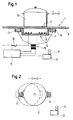
- a cooktop 1 according to FIG. 1 has a cooktop 3 made of glass ceramic circular cooking zone 4. To mark the cooking zone 4 on the hotplate 3 a known zone decor printed. Below the hotplate 3 is in the area the cooking zone 4 a known pot-shaped heating element 5 is arranged. This has a heating wire 9 arranged in an insulation pot 7. The heating wire 9 can be connected to mains voltage via a switch 10. To control the The hob 1 has a heating power or for setting the desired cooking level Control unit 11 on. The control unit 11 is also provided with a main switch 12 connected by which, as required by the relevant safety regulations, the hob 1 or all of its electrical consumers can be switched from the network.
- the hob 1 has display elements 13 which are in the form of seven-segment displays, Arranged in a manner known per se below the hotplate 3 in the hob 1 are.
- the power level is for the cooking zone 4 of the hob 1 "8" set and indicated by the seven-segment display 13.
- Isolation pot 7 are opposite each other in the form of metallic Electrodes a first sensor element 15 and a second sensor element 17 directly below the hotplate 3 arranged.
- the two sensor elements 15 and 17 are fed via a sensor circuit 19 or the control circuit 11 and their Capacities evaluated.
- a pot 21 exactly above the heating element 5.
- the setting of the desired The power level of the heating element 5 takes place according to FIG. 2 as follows:
- the position of the pot 21 according to FIG. 1 is shown in solid lines in FIG shown. In this position, the heating position, the pot 21 protrudes exactly the heating element 5. Both sensor elements 15 and 17 provide the information that in there is no pot 21 in their area. The power level already set "8" remains unchanged.
- the selection position detects the first Sensor element 15 that the pot 21 is not present.
- the sensor element 17 however, detects that the pot 21 is present.
- the pot 21 is therefore in the selection position.
- a time counter of the control unit 11 starts running. The heat setting will change approximately every 0.5 seconds increased by a cooking level and the increase is visualized by the display element 13.
- the power level is changed by turning the pot 21 and secondly from the position of the pot 21 in the cooking zone 4 directly to the desired one Cooking level of cooking zone 4 closed.
- the Pot has a magnetic element 25 in its bottom region.
- Below the Glass plate are the first sensor element 15 along a section of the The circumference of the cooking zone 4 arranged numerous reed switches.
Landscapes
- Chemical & Material Sciences (AREA)
- Engineering & Computer Science (AREA)
- Ceramic Engineering (AREA)
- Electric Stoves And Ranges (AREA)
- Control Of Resistance Heating (AREA)
- Baking, Grill, Roasting (AREA)
- Cookers (AREA)
Applications Claiming Priority (2)
| Application Number | Priority Date | Filing Date | Title |
|---|---|---|---|
| DE1998125321 DE19825321C1 (de) | 1998-06-05 | 1998-06-05 | Kochfeld mit Bedieneinheit zur Vorgabe der Leistungsstufe und Verfahren zum Einstellen der Leistungsstufe eines Heizelementes eines Kochfeldes |
| DE19825321 | 1998-06-05 |
Publications (2)
| Publication Number | Publication Date |
|---|---|
| EP0967839A2 true EP0967839A2 (fr) | 1999-12-29 |
| EP0967839A3 EP0967839A3 (fr) | 2001-10-31 |
Family
ID=7870120
Family Applications (1)
| Application Number | Title | Priority Date | Filing Date |
|---|---|---|---|
| EP99110681A Withdrawn EP0967839A3 (fr) | 1998-06-05 | 1999-06-02 | Plaque de cuisson munie d'une unité de commande dans le but de déterminer le niveau de puissance fournie |
Country Status (2)
| Country | Link |
|---|---|
| EP (1) | EP0967839A3 (fr) |
| DE (1) | DE19825321C1 (fr) |
Cited By (11)
| Publication number | Priority date | Publication date | Assignee | Title |
|---|---|---|---|---|
| EP1344983A2 (fr) | 2002-03-13 | 2003-09-17 | Cherry GmbH | Arrangement pour le contrôle d'un plaque de cuisson |
| EP1758431A2 (fr) | 2005-08-23 | 2007-02-28 | E.G.O. ELEKTRO-GERÄTEBAU GmbH | Plaque de cuisson commandée électroniquement comportant plusieurs feux et le procédé de commande de tels feux |
| WO2008055370A1 (fr) * | 2006-11-09 | 2008-05-15 | Menu-System Ag | Procédé de commande d'un appareil de cuisson par induction, et appareil de cuisson par induction |
| WO2009024899A3 (fr) * | 2007-08-21 | 2009-04-30 | Koninkl Philips Electronics Nv | Appareil de chauffage par induction |
| EP2276322A1 (fr) | 2009-07-16 | 2011-01-19 | E.G.O. ELEKTRO-GERÄTEBAU GmbH | Procédé de fonctionnement d'un champ de cuisson |
| EP2741010A1 (fr) * | 2012-12-05 | 2014-06-11 | Electrolux Home Products Corporation N.V. | Plaque de cuisson comprenant une interface utilisateur |
| EP2527747B1 (fr) * | 2011-05-24 | 2018-01-03 | Diehl AKO Stiftung & Co. KG | Dispositif de commande d'un champ de cuisson |
| EP3855868A1 (fr) * | 2020-01-22 | 2021-07-28 | E.G.O. Elektro-Gerätebau GmbH | Procédé de commande de l'alimentation électrique fournie à une bobine de chauffage par induction d'une table de cuisson à induction et table de cuisson à induction |
| EP4067749A4 (fr) * | 2019-11-28 | 2023-11-29 | LG Electronics Inc. | Cuiseur électrique assurant des fonctions spécifiques en fonction de gestes de l'utilisateur |
| EP4067748A4 (fr) * | 2019-11-25 | 2024-02-28 | Lg Electronics Inc. | Cuiseur électrique fournissant des fonctions spécifiques sans intervention de l'utilisateur |
| US12066192B2 (en) | 2018-11-29 | 2024-08-20 | Broan-Nutone Llc | Smart indoor air venting system |
Families Citing this family (5)
| Publication number | Priority date | Publication date | Assignee | Title |
|---|---|---|---|---|
| DE102004011749A1 (de) * | 2004-03-02 | 2005-09-15 | E.G.O. Elektro-Gerätebau GmbH | Elektronisch gesteuertes Kochfeld mit mehreren Kochstellen und Verfahren zum Betrieb eines solchen Kochfeldes |
| DE102004016631A1 (de) * | 2004-03-29 | 2005-11-10 | E.G.O. Elektro-Gerätebau GmbH | Vorrichtung und Verfahren zur Überwachung der Temperatur eines Kochgeschirrs auf einer Abdeckung eines Kochfeldes sowie von weiteren Vorgängen auf der Abdeckung |
| DE102004059822B4 (de) * | 2004-12-03 | 2011-02-24 | E.G.O. Elektro-Gerätebau GmbH | Verfahren zum Betrieb eines Induktionskochfelds |
| DE102009020905A1 (de) | 2009-05-12 | 2010-12-09 | Diehl Ako Stiftung & Co. Kg | Kochfeld |
| DE102011102394B4 (de) * | 2011-05-24 | 2013-01-31 | Diehl Ako Stiftung & Co. Kg | Vorrichtung und Verfahren zur Bedienung eines Kochfeldes |
Citations (1)
| Publication number | Priority date | Publication date | Assignee | Title |
|---|---|---|---|---|
| DE4007680A1 (de) | 1990-03-10 | 1991-09-19 | Grass Ag | Heizplatte |
Family Cites Families (4)
| Publication number | Priority date | Publication date | Assignee | Title |
|---|---|---|---|---|
| DE3209260A1 (de) * | 1982-03-13 | 1983-09-22 | Bosch-Siemens Hausgeräte GmbH, 7000 Stuttgart | Kochfeld aus glaskermaischem material |
| DE3804170A1 (de) * | 1987-04-06 | 1989-08-24 | Kueppersbusch | Kochgeraet |
| FR2667477A1 (fr) * | 1990-09-28 | 1992-04-03 | Philips Electronique Lab | Table chauffante a commandes automatiques. |
| EP0620698A1 (fr) * | 1993-04-13 | 1994-10-19 | Whirlpool Europe B.V. | Appareil pour détecter la présence d'une récipient pour aliments, tel qu'une casserole ou similaire, sur une plaque de cuisson en vitro-céramique |
-
1998
- 1998-06-05 DE DE1998125321 patent/DE19825321C1/de not_active Expired - Fee Related
-
1999
- 1999-06-02 EP EP99110681A patent/EP0967839A3/fr not_active Withdrawn
Patent Citations (1)
| Publication number | Priority date | Publication date | Assignee | Title |
|---|---|---|---|---|
| DE4007680A1 (de) | 1990-03-10 | 1991-09-19 | Grass Ag | Heizplatte |
Cited By (18)
| Publication number | Priority date | Publication date | Assignee | Title |
|---|---|---|---|---|
| EP1344983A3 (fr) * | 2002-03-13 | 2006-04-19 | Cherry GmbH | Arrangement pour le contrôle d'un plaque de cuisson |
| EP1344983A2 (fr) | 2002-03-13 | 2003-09-17 | Cherry GmbH | Arrangement pour le contrôle d'un plaque de cuisson |
| EP1758431A3 (fr) * | 2005-08-23 | 2009-01-07 | E.G.O. ELEKTRO-GERÄTEBAU GmbH | Plaque de cuisson commandée électroniquement comportant plusieurs feux et le procédé de commande de tels feux |
| EP1758431A2 (fr) | 2005-08-23 | 2007-02-28 | E.G.O. ELEKTRO-GERÄTEBAU GmbH | Plaque de cuisson commandée électroniquement comportant plusieurs feux et le procédé de commande de tels feux |
| CN101574014B (zh) * | 2006-11-09 | 2012-04-11 | 菜单-系统股份公司 | 用于控制感应灶具的方法和感应灶具 |
| WO2008055370A1 (fr) * | 2006-11-09 | 2008-05-15 | Menu-System Ag | Procédé de commande d'un appareil de cuisson par induction, et appareil de cuisson par induction |
| WO2009024899A3 (fr) * | 2007-08-21 | 2009-04-30 | Koninkl Philips Electronics Nv | Appareil de chauffage par induction |
| EP2276322A1 (fr) | 2009-07-16 | 2011-01-19 | E.G.O. ELEKTRO-GERÄTEBAU GmbH | Procédé de fonctionnement d'un champ de cuisson |
| DE102009034203A1 (de) | 2009-07-16 | 2011-01-20 | E.G.O. Elektro-Gerätebau GmbH | Verfahren zum Betrieb eines Kochfelds |
| EP2527747B1 (fr) * | 2011-05-24 | 2018-01-03 | Diehl AKO Stiftung & Co. KG | Dispositif de commande d'un champ de cuisson |
| US9557064B2 (en) | 2012-12-05 | 2017-01-31 | Electrolux Home Products Corporation N.V. | Cooking hob including a user interface |
| WO2014086566A1 (fr) * | 2012-12-05 | 2014-06-12 | Electrolux Home Products Corporation N. V. | Plaque de cuisson comprenant une interface utilisateur |
| CN105051460B (zh) * | 2012-12-05 | 2017-07-07 | 伊莱克斯家用产品股份有限公司 | 包括使用者界面的烹饪炉架及其操作方法 |
| EP2741010A1 (fr) * | 2012-12-05 | 2014-06-11 | Electrolux Home Products Corporation N.V. | Plaque de cuisson comprenant une interface utilisateur |
| US12066192B2 (en) | 2018-11-29 | 2024-08-20 | Broan-Nutone Llc | Smart indoor air venting system |
| EP4067748A4 (fr) * | 2019-11-25 | 2024-02-28 | Lg Electronics Inc. | Cuiseur électrique fournissant des fonctions spécifiques sans intervention de l'utilisateur |
| EP4067749A4 (fr) * | 2019-11-28 | 2023-11-29 | LG Electronics Inc. | Cuiseur électrique assurant des fonctions spécifiques en fonction de gestes de l'utilisateur |
| EP3855868A1 (fr) * | 2020-01-22 | 2021-07-28 | E.G.O. Elektro-Gerätebau GmbH | Procédé de commande de l'alimentation électrique fournie à une bobine de chauffage par induction d'une table de cuisson à induction et table de cuisson à induction |
Also Published As
| Publication number | Publication date |
|---|---|
| EP0967839A3 (fr) | 2001-10-31 |
| DE19825321C1 (de) | 2000-02-10 |
Similar Documents
| Publication | Publication Date | Title |
|---|---|---|
| DE3744372C2 (de) | Leistungssteuerungsverfahren zum Schutz von Glaskeramikkochflächen | |
| DE69100010T2 (de) | Vorrichtung zur heizstellenregelung bei einem kochgeraet durch sensortasten. | |
| EP0967839A2 (fr) | Plaque de cuisson munie d'une unité de commande dans le but de déterminer le niveau de puissance fournie | |
| DE4022846C2 (de) | Vorrichtung zur Leistungssteuerung und -begrenzung bei einer Heizfläche aus Glaskeramik oder einem vergleichbaren Material | |
| EP0442275B1 (fr) | Dispositif ou détection d'un récipient placé dans une zone de chauffage d'un appareil de cuisson ou de chauffage | |
| DE4130337C2 (de) | Verfahren zum Betrieb einer elektrischen Heizeinheit und elektrische Heizeinheit | |
| DE3837096C2 (de) | Leistungssteueranordnung für ein Glaskeramik-Kochfeld | |
| DE69834791T2 (de) | Heizelement | |
| DE19918290C1 (de) | Kochgerät mit einfach handhabbarer Bedieneinrichtung | |
| DE102016101036B4 (de) | Kochmulde mit einer Glaskeramik-Kochfläche | |
| EP0690659B1 (fr) | Unité de cuisson à commande par infrarouge | |
| DE69026553T2 (de) | Temperaturmessvorrichtung für Induktionskochgerät und Gerät mit einer solchen Vorrichtung | |
| AT389612B (de) | Elektrische strahlungsheizeinheit | |
| DE19648397A1 (de) | Verfahren und Vorrichtung zum Erkennen des Kochpunktes von Kochgut | |
| EP0374868A1 (fr) | Plaque de cuisson | |
| EP2258987A2 (fr) | Appareil ménager doté d'un écran tactile | |
| DE60201683T2 (de) | Kochgerät | |
| DE3117205A1 (de) | Optoelektronische kochfeldsteuerung | |
| EP0780081B2 (fr) | Méthode pour régler automatiquement des emplacements de cuisson chauffants | |
| DE3934157C2 (de) | Kochmulde | |
| DE4413979C2 (de) | Sensorgesteuerte Garungseinheit und Gargerät | |
| DE102004005111B4 (de) | Hausgerätebedienvorrichtung | |
| DE102004059822B4 (de) | Verfahren zum Betrieb eines Induktionskochfelds | |
| DE19610073A1 (de) | Glaskeramikkochfeld | |
| DE102004016631A1 (de) | Vorrichtung und Verfahren zur Überwachung der Temperatur eines Kochgeschirrs auf einer Abdeckung eines Kochfeldes sowie von weiteren Vorgängen auf der Abdeckung |
Legal Events
| Date | Code | Title | Description |
|---|---|---|---|
| PUAI | Public reference made under article 153(3) epc to a published international application that has entered the european phase |
Free format text: ORIGINAL CODE: 0009012 |
|
| AK | Designated contracting states |
Kind code of ref document: A2 Designated state(s): AT BE CH CY DE DK ES FI FR GB GR IE IT LI LU MC NL PT SE |
|
| AX | Request for extension of the european patent |
Free format text: AL;LT;LV;MK;RO;SI |
|
| PUAL | Search report despatched |
Free format text: ORIGINAL CODE: 0009013 |
|
| AK | Designated contracting states |
Kind code of ref document: A3 Designated state(s): AT BE CH CY DE DK ES FI FR GB GR IE IT LI LU MC NL PT SE |
|
| AX | Request for extension of the european patent |
Free format text: AL;LT;LV;MK;RO;SI |
|
| STAA | Information on the status of an ep patent application or granted ep patent |
Free format text: STATUS: THE APPLICATION HAS BEEN WITHDRAWN |
|
| 18W | Application withdrawn |
Withdrawal date: 20020306 |