EP0328095A2 - Method of producing a gas burner head from a blank of sheet metal - Google Patents
Method of producing a gas burner head from a blank of sheet metal Download PDFInfo
- Publication number
- EP0328095A2 EP0328095A2 EP89102223A EP89102223A EP0328095A2 EP 0328095 A2 EP0328095 A2 EP 0328095A2 EP 89102223 A EP89102223 A EP 89102223A EP 89102223 A EP89102223 A EP 89102223A EP 0328095 A2 EP0328095 A2 EP 0328095A2
- Authority
- EP
- European Patent Office
- Prior art keywords
- burner
- sheet metal
- longitudinal
- metal blank
- walls
- Prior art date
- Legal status (The legal status is an assumption and is not a legal conclusion. Google has not performed a legal analysis and makes no representation as to the accuracy of the status listed.)
- Granted
Links
Images


Classifications
-
- F—MECHANICAL ENGINEERING; LIGHTING; HEATING; WEAPONS; BLASTING
- F23—COMBUSTION APPARATUS; COMBUSTION PROCESSES
- F23D—BURNERS
- F23D14/00—Burners for combustion of a gas, e.g. of a gas stored under pressure as a liquid
- F23D14/46—Details
-
- B—PERFORMING OPERATIONS; TRANSPORTING
- B21—MECHANICAL METAL-WORKING WITHOUT ESSENTIALLY REMOVING MATERIAL; PUNCHING METAL
- B21D—WORKING OR PROCESSING OF SHEET METAL OR METAL TUBES, RODS OR PROFILES WITHOUT ESSENTIALLY REMOVING MATERIAL; PUNCHING METAL
- B21D53/00—Making other particular articles
Definitions
- the invention relates first of all to a method for producing a burner plate that forms the burner plate, delimits an elongated burner chamber with longitudinal side walls and, in a central trough, a bearing for an upper part of a gas burner that has a longitudinal cooling tube from a sheet metal blank.
- the object of the invention is to provide a method which makes it possible to produce this upper part of the burner with all of its essential components for the design of the burner chamber in a few, easy-to-perform operations from a single sheet metal blank.
- this sheet metal is closed first on the two end faces Cut to form certain areas to form the end walls of the burner chamber, then in the middle of the width of the sheet metal blank, the trough intended for storage of the cooling tube is formed by pulling, then the two inner longitudinal areas provided on both sides of this trough, to form the burner plate, with respect to the outside, for formation of the longitudinal side walls of the burner chamber, certain longitudinal regions are bent into an inclined position and finally these two outer longitudinal regions are deformed into a position parallel to one another and are pressed against one another at their desired distance corresponding to the width of the burner chamber.
- a burner upper part can be produced in a comparatively very simple and cost-effective manner, which is characterized by a high and easily realizable gas tightness of the burner chamber and by a technically advantageous design of the flame area.
- outer edge zones of the two inner longitudinal regions can be integrated into one together with adjacent inner edge zones of the two outer longitudinal regions be bent towards the center of the width of the burner.
- the front edges of the two inner longitudinal regions can also be deformed into flanges for this purpose.
- This process step is very advantageous and can be coupled simultaneously with the pressing of the two longitudinal side walls of the upper burner part at their desired distance, that is to say with the last process step.
- the invention also extends to a sheet metal blank for carrying it out.
- a sheet metal blank has a length corresponding to the length of the burner and protruding on both ends in the longitudinal direction of the sheet metal blank, which can be bent to form end walls of the burner chamber and is arranged on both sides and has an extension protruding in the middle of the width of each end face and deformable for storing the cooling tube on.
- these extensions In order to be able to produce a closed end face of the burner chamber with such extensions, these extensions have an edge which is inclined to match the oblique course of the burner plate of the burner, whereas their edge directed transversely to the longitudinal direction of the sheet metal blank runs perpendicular to this longitudinal direction and the outer edge runs parallel to this longitudinal direction .
- the invention also extends to a method according to the invention according to the sheet metal blank produced top part of a gas burner.
- Such an upper part formed from a single sheet metal blank can be fitted with a snug fit on the upper edges of the walls of a gas-air mixture distributor, the two outer longitudinal regions forming the side walls of the upper part and together delimiting a burner chamber, which is at the top by one of the two Inner longitudinal areas formed, with a longitudinal trough for a cooling tube and with this trough extending obliquely upwards on both sides and through which mixture outlet openings are profiled burner plate.
- the method according to the invention enables a gas-tight connection of the end wall parts formed by the extensions of the sheet metal blank arranged on both ends with the end edges of the inner longitudinal regions of the blank forming the burner plate.
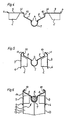
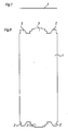
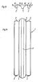
- FIGS. 7 and 8 first show the still flat, undeformed sheet metal blank 1, on the end faces of which two lateral extensions 2 and a central projection 3 each protrude.
- the extensions 2 later serve to form end walls delimiting the end faces of the burner chamber, the extensions 3 and the knobs 4 shown in FIG. 1 serve to hold a cooling tube 5 in a longitudinal trough 7 (FIG. 6).
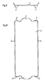
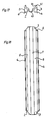
- the extensions 2 are bent approximately perpendicular to the plane of the sheet metal blank 1, as shown in FIGS. 1, 9 and 10, and at the same time the two longitudinal edges 6 of the sheet metal blank 1 are bent into a position inclined to the plane thereof.
- the trough 7 for the cooling tube 5 is formed by pulling, the same process step also being used on both sides of the trough 7 to serve as the burner plate and to be equipped with the mixture outlet openings stretching inner longitudinal regions 8 are deformed into an inclined position with respect to the outer longitudinal regions 9.
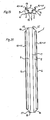
- the third method step comprises pre-bending those edge zones 10 of the inner longitudinal regions 8 which directly adjoin the outer longitudinal regions 9. These edge zones 10 are pre-bent with respect to the edge zones 11 of the two outer longitudinal regions 9 into a position which is initially perpendicular to these longitudinal regions 9.
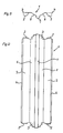
- the fourth method step comprises raising the two outer longitudinal regions 9, which thereby come to lie in a common horizontal plane, the acute angle between the inner longitudinal regions 8 and their edge zones 10 being reduced.
- the two outer longitudinal regions 9 are bent into a position parallel to one another, but do not yet have their desired distance, but an excessively large distance.
- the edge zones 11 of these longitudinal regions 9 are folded, namely in a width which corresponds to the width of the edge zones 10 of the two inner longitudinal regions 8.
- the end wall of the trough 7 for the cooling tube 5 receives a collar 15 formed from the extension 3 of the sheet metal blank 1, which serves for the sealing, and the two inner longitudinal regions 8 with the mixture outlet openings each receive a joint which also serves to seal the end walls of the burner chamber 14 the end extensions 2 of the sheet metal blank 1 sealing flange 16.
- edge zones 10 and 11 of the inner and outer longitudinal regions 8 and 9 are bent inwards together and form a solid both when they lie against each other shielding for the flame area of the burner and a secondary air duct.
Landscapes
- Engineering & Computer Science (AREA)
- Mechanical Engineering (AREA)
- Chemical & Material Sciences (AREA)
- Combustion & Propulsion (AREA)
- General Engineering & Computer Science (AREA)
- Gas Burners (AREA)
- Shaping Metal By Deep-Drawing, Or The Like (AREA)
Abstract
Aus einem einzigen Blechzuschnitt (1) werden zuerst an den beiden Stirnseiten dieses Blechzuschnittes (1) zur Bildung der Stirnwände der Brennkammer (14) bestimmte Bereiche (2) abgekantet, sodann wird in der Breitenmitte des Blechzuschnittes (1) die zur Lagerung eines längsverlaufenden Kühlrohres (5) bestimmte Mulde durch Ziehen geformt, sodann werden die beiden beidseits dieser Mulde (7) befindlichen, zur Bildung der Brennerplatte vorgesehenen inneren Längsbereiche (8) in bezug zu äußeren, zur Bildung der Längsseitenwände der Brennerkammer (14) bestimmten Längsbereichen (9) in eine Schrägstellung abgekantet, und schließlich werden diese beiden äußeren Längsbereiche (9) in eine zueinander parallele Lage verformt und auf ihren der Breite der Brennerkammer (14) entsprechenden Soll-Abstand gegeneinander gedrückt. Dieses derart geformte Oberteil des Brenners ist an seinen Stirnseiten gasdicht und kann mit Paßsitz auf die längs seitigen Wandungen (13) eines Gemischverteilers (12) aufgesetzt und mit diesen Wandungen (13) gasdicht verbunden werden.From a single sheet metal blank (1), certain areas (2) are first folded on the two end faces of this sheet metal blank (1) to form the end walls of the combustion chamber (14), then in the middle of the width of the sheet metal blank (1) is the one for storing a longitudinal cooling tube (5) certain trough is formed by pulling, then the two inner longitudinal areas (8) located on both sides of this trough (7) and intended to form the burner plate are formed with respect to outer longitudinal areas (9) intended to form the longitudinal side walls of the burner chamber (14) folded into an inclined position, and finally these two outer longitudinal regions (9) are deformed into a position parallel to one another and pressed against one another at their desired distance corresponding to the width of the burner chamber (14). This shaped upper part of the burner is gas-tight on its end faces and can be fitted with a snug fit on the longitudinal walls (13) of a mixture distributor (12) and connected gas-tight to these walls (13).
Description
Die Erfindung betrifft zunächst ein Verfahren zur Herstellung eines die Brennerplatte bildenden, mit Längsseitenwänden eine längliche Brennerkammer begrenzenden und in einer mittigen Mulde eine Lagerung für ein längsverlaufendes Kühlrohr aufweisenden Oberteiles eines Gasbrenners aus einem Blechzuschnitt.The invention relates first of all to a method for producing a burner plate that forms the burner plate, delimits an elongated burner chamber with longitudinal side walls and, in a central trough, a bearing for an upper part of a gas burner that has a longitudinal cooling tube from a sheet metal blank.
Aufgabe der Erfindung ist es, ein Verfahren zu schaffen, das es ermöglicht, dieses Oberteil des Brenners mit allen seinen für die Gestaltung der Brennerkammer wesentlichen Bestandteilen in wenigen, problemlosen vollziehbaren Arbeitsgängen aus einem einzigen Blechzuschnitt herzustellen.The object of the invention is to provide a method which makes it possible to produce this upper part of the burner with all of its essential components for the design of the burner chamber in a few, easy-to-perform operations from a single sheet metal blank.
Erfindungsgemäß ist zur Erreichung dieses Zieles vorgesehen, daß zuerst an den beiden Stirnseiten dieses Blechzu schnittes zur Bildung der Stirnwände der Brennerkammer bestimmte Bereiche abgekantet, sodann in der Breitenmitte des Blechzuschnittes die zur Lagerung des Kühlrohres bestimmte Mulde durch Ziehen geformt, sodann die beiden beidseits dieser Mulde befindlichen, zur Bildung der Brennerplatte vorgesehenen inneren Längsbereiche in bezug zu äußeren, zur Bildung der Längsseitenwände der Brennerkammer bestimmten Längsbereichen in eine Schrägstellung abgekantet und schließlich diese beiden äußeren Längsbereiche in eine zueinander parallele Lage verformt und auf ihren der Breite der Brennerkammer entsprechenden Soll-Abstand gegeneinander gedrückt werden.According to the invention, in order to achieve this goal, it is provided that this sheet metal is closed first on the two end faces Cut to form certain areas to form the end walls of the burner chamber, then in the middle of the width of the sheet metal blank, the trough intended for storage of the cooling tube is formed by pulling, then the two inner longitudinal areas provided on both sides of this trough, to form the burner plate, with respect to the outside, for formation of the longitudinal side walls of the burner chamber, certain longitudinal regions are bent into an inclined position and finally these two outer longitudinal regions are deformed into a position parallel to one another and are pressed against one another at their desired distance corresponding to the width of the burner chamber.
Mit diesen Verfahrensschritten läßt sich auf vergleichsweise sehr einfache und kostengünstige Weise ein Brenneroberteil anfertigen, das sich durch eine hohe und einfach realisierbare Gasdichtheit der Brennerkammer und durch eine technisch vorteilhafte Gestaltung des Flammenbereiches auszeichnet.With these method steps, a burner upper part can be produced in a comparatively very simple and cost-effective manner, which is characterized by a high and easily realizable gas tightness of the burner chamber and by a technically advantageous design of the flame area.
Zur Bildung seitlicher Abschirmwände des Flammenbereiches des Brenners, die auch zu einer günstigen Führung der Sekundärluft beitragen, können nach einer bevorzugten Ausführungsform des Verfahrens äußere Randzonen der beiden inneren Längsbereiche gemeinsam mit benachbarten inneren Randzonen der beiden äußeren Längsbereiche in eine ein wärts gegen die Breitenmitte des Brenners weisende Schräglage gebogen werden.To form lateral shielding walls of the flame region of the burner, which also contribute to a favorable guidance of the secondary air, according to a preferred embodiment of the method, outer edge zones of the two inner longitudinal regions can be integrated into one together with adjacent inner edge zones of the two outer longitudinal regions be bent towards the center of the width of the burner.
Die Herstellung solcher doppellagiger Abschirmwände wird dann besonders vereinfacht, wenn die beiden äußeren Randzonen der beiden inneren Längsbereiche zunächst gleichzeitig mit dem Abkanten der beiden äußeren Längsbereiche nur vorgebogen und sodann mit diesen äußeren Längsbereichen gemeinsam hochgestellt werden.The manufacture of such double-layered shielding walls is particularly simplified if the two outer edge zones of the two inner longitudinal regions are initially only pre-bent simultaneously with the folding of the two outer longitudinal regions and then raised together with these outer longitudinal regions.
Zur Herstellung der endgültigen Soll-Lage dieser Abschirmwände brauchen dann nur die inneren Randzonen der beiden äußeren Längsbereiche gemeinsam mit dem Parallelstellen dieser äußeren Längsbereiche in eine Schräglage abgekantet und mit den äußeren Randzonen der inneren Längsbereiche gemeinsam in dieser Soll-Schräglage einwärts gedrückt werden.To produce the final desired position of these shielding walls, only the inner edge zones of the two outer longitudinal regions need to be bent together with the parallel positioning of these outer longitudinal regions into an inclined position and pressed inwards together with the outer edge zones of the inner longitudinal regions in this desired inclined position.
Zum gasdichten Abschluß der Stirnseiten der Brennerkammer und zur Versteifung der Stirnwände empfiehlt es sich, Teile eines stirnseitigen, in der Breitenmitte des Blechzuschnittes an beiden Stirnseiten angeordneten Vorsprunges zu einem Kragen der zur Lagerung eines Kühlrohres dienenden Mulde der Brennerplatte zu verformen.For the gas-tight closure of the end faces of the burner chamber and for stiffening the end walls, it is advisable to deform parts of an end-side projection arranged in the middle of the width of the sheet metal blank on both end faces into a collar of the trough of the burner plate which serves to mount a cooling tube.
Auch die stirnseitigen Ränder der beiden inneren Längsbereiche können zu diesem Zweck zu Bördeln verformt werden.The front edges of the two inner longitudinal regions can also be deformed into flanges for this purpose.
Dieser Verfahrensschritt ist sehr vorteilhaft, gleichzeitig mit dem Gegeneinanderdrücken der beiden Längsseitenwände des Brenneroberteiles auf deren Soll-Distanz, also mit dem letzten Verfahrensschritt, koppelbar.This process step is very advantageous and can be coupled simultaneously with the pressing of the two longitudinal side walls of the upper burner part at their desired distance, that is to say with the last process step.
Im Zusammenhang mit dem Verfahren erstreckt sich die Erfindung auch auf einen Blechzuschnitt zu dessen Durchführung. Erfindungsgemäß weist ein solcher Blechzuschnitt eine der Länge des Brenners entsprechende Länge und an den beiden Stirnseiten in Längsrichtung des Blechzuschnittes ausragende, zur Bildung von Stirnwänden der Brennerkammer abkantbare, beidseits angeordnete Fortsätze sowie je einen in der Breitenmitte jeder Stirnseite ausragenden, zur Lagerung des Kühlrohres verformbaren Fortsatz auf.In connection with the method, the invention also extends to a sheet metal blank for carrying it out. According to the invention, such a sheet metal blank has a length corresponding to the length of the burner and protruding on both ends in the longitudinal direction of the sheet metal blank, which can be bent to form end walls of the burner chamber and is arranged on both sides and has an extension protruding in the middle of the width of each end face and deformable for storing the cooling tube on.
Um mit solchen Fortsätzen eine geschlossene Stirnseite der Brennerkammer anfertigen zu können, weisen diese Fortsätze mit einer dem Schrägverlauf der Brennerplatte des Brenners entsprechend schrägverlaufenden Kante zueinander, wogegen ihre quer zur Längsrichtung des Blechzuschnittes gerichtete Kante senkrecht zu dieser Längsrichtung und die Außenkante parallel zu dieser Längsrichtung verlaufen.In order to be able to produce a closed end face of the burner chamber with such extensions, these extensions have an edge which is inclined to match the oblique course of the burner plate of the burner, whereas their edge directed transversely to the longitudinal direction of the sheet metal blank runs perpendicular to this longitudinal direction and the outer edge runs parallel to this longitudinal direction .
Schließlich erstreckt sich die Erfindung auch auf einen nach dem erfindungsgemäßen Verfahren aus einem erfin dungsgemäßen Blechzuschnitt hergestellten Oberteil eines Gasbrenners.Finally, the invention also extends to a method according to the invention according to the sheet metal blank produced top part of a gas burner.
Ein solches aus einem einzigen Blechzuschnitt geformtes Oberteil ist mit Paßsitz auf die oberen Ränder der Wandungen eines Gas-Luft-Gemisch-Verteilers aufsetzbar, wobei die beiden äußeren Längsbereiche die Seitenwandungen des Oberteiles bilden und gemeinsam eine Brennerkammer begrenzen, die oben durch eine aus den beiden inneren Längsbereichen gebildete, mit einer längsverlaufenden Mulde für ein Kühlrohr und mit von dieser Mulde beidseits schräg aufwärts verlaufenden, von Gemischaustrittsöffnungen durchsetzten Seitenbereichen profilierte Brennerplatte abgeschlossen ist.Such an upper part formed from a single sheet metal blank can be fitted with a snug fit on the upper edges of the walls of a gas-air mixture distributor, the two outer longitudinal regions forming the side walls of the upper part and together delimiting a burner chamber, which is at the top by one of the two Inner longitudinal areas formed, with a longitudinal trough for a cooling tube and with this trough extending obliquely upwards on both sides and through which mixture outlet openings are profiled burner plate.
Das erfindungsgemäße Verfahren ermöglicht eine gasdichte Verbindung der von den stirnseitig beidseits angeordneten Fortsätzen des Blechzuschnittes gebildeten Stirnwandteile mit den stirnseitigen Rändern der die Brennerplatte bildenden inneren Längsbereiche des Zuschnittes.The method according to the invention enables a gas-tight connection of the end wall parts formed by the extensions of the sheet metal blank arranged on both ends with the end edges of the inner longitudinal regions of the blank forming the burner plate.
Anhand der Zeichnungen ist ein Ausführungsbeispiel des erfindungsgemäßen Verfahrens veranschaulicht und nachstehend erläutert.An exemplary embodiment of the method according to the invention is illustrated with reference to the drawings and explained below.
Im einzelnen zeigen die
Figuren 1 bis 6 den Ablauf des Verfahrens in Querschnit ten durch den schrittweise verformten Blechzuschnitt undFiguren 7 bis 20 stellen diese Verfahrensschritte in jeweils einem schematischen Querschnitt und einer Draufsicht dar.
- Figures 1 to 6 the sequence of the method in cross section through the gradually deformed sheet metal blank and
- FIGS. 7 to 20 each show these method steps in a schematic cross section and a top view.
Die Figuren 7 und 8 zeigen zunächst den noch ebenen, unverformten Blechzuschnitt 1, an dessen Stirnseiten je zwei seitliche Fortsätze 2 und je ein mittiger Vorsprung 3 ausragen.FIGS. 7 and 8 first show the still flat, undeformed sheet metal blank 1, on the end faces of which two
Die Fortsätze 2 dienen später zur Bildung von die Stirnseiten der Brennerkammer begrenzenden Stirnwandungen, die Fortsätze 3 sowie die aus Figur 1 ersichtlichen Noppen 4 dienen der Halterung eines Kühlrohres 5 in einer längsverlaufenden Mulde 7 (Figur 6).The
Im ersten Verfahrensschritt werden gemäß der Figuren 1, 9 und 10 die Fortsätze 2 etwa senkrecht zur Ebene des Blechzuschnittes 1 abgekantet, und gleichzeitig werden die beiden Längsränder 6 des Blechzuschnittes 1 in eine zu dessen Ebene schräge Stellung abgebogen.In the first process step, the
Im zweiten Verfahrensschritt wird gemäß der Figuren 2, 11 und 12 die Mulde 7 für das Kühlrohr 5 durch Ziehen geformt, wobei im selben Verfahrensschritt auch die später als Brennerplatte dienenden und mit den Gemischaustrittsöffnungen auszustattenden, sich beidseits der Mulde 7 er streckenden inneren Längsbereiche 8 in eine Schräglage in bezug zu den äußeren Längsbereichen 9 verformt werden.In the second process step, according to FIGS. 2, 11 and 12, the
Der dritte Verfahrensschritt umfaßt gemäß der Figuren 3, 13 und 14 ein Vorbiegen jener Randzonen 10 der inneren Längsbereiche 8, die unmittelbar an die äußeren Längsbereiche 9 anschließen. Dabei werden diese Randzonen 10 in bezug zu den Randzonen 11 der beiden äußeren Längsbereiche 9 in eine zunächst zu diesen Längsbereichen 9 senkrechte Stellung vorgebogen.According to FIGS. 3, 13 and 14, the third method step comprises pre-bending those
Der vierte Verfahrensschritt umfaßt gemäß der Figuren 4, 15 und 16 ein Hochstellen der beiden äußeren Längsbereiche 9, die dadurch in eine gemeinsame waagerechte Ebene zu liegen kommen, wobei sich der spitze Winkel zwischen den inneren Längsbereichen 8 und deren Randzonen 10 verringert.According to FIGS. 4, 15 and 16, the fourth method step comprises raising the two outer
Im fünften Verfahrensschritt werden gemäß der Figuren 5, 17 und 18 die beiden äußeren Längsbereiche 9 in eine zueinander parallele Lage gebogen, weisen jedoch noch nicht ihre Soll-Distanz, sondern eine zu große Distanz auf. Mit diesem Abbiegen der äußeren Längsbereiche 9 gleichzeitig werden die Randzonen 11 dieser Längsbereiche 9 abgekantet, und zwar in einer Breite, die der Breite der Randzonen 10 der beiden inneren Längsbereiche 8 entspricht. In der endgültigen Form nach den Figuren 6, 19 und 20 werden die beiden äußeren Längsbereiche 9 als Längsseitenwände der fertigen Brennerkammer 14 auf die oberen Ränder der Längsseitenwandungen 13 einer Gemischverteilerkammer 12 aufgesetzt und auf ihren Soll-Abstand, der der Breite der Brennerkammer 14 entspricht, gegeneinandergedrückt, wobei die Fortsätze 2 gemeinsam jeweils eine Stirnwand der Brennerkammer 14 bilden und diese Brennerkammer 14 gasdicht abschließen.In the fifth method step, according to FIGS. 5, 17 and 18, the two outer
Die im ersten Verfahrensschritt abgebogenen Längsränder 6 der äußeren Längsbereiche 9, also nunmehr der Längsseitenwände der Brennerkammer 14, erleichtern das paßgenaue Aufsetzen des Oberteiles auf die Längsseitenwandungen 13 der Gemischverteilerkammer 12.The
Der Stirnwand der Mulde 7 für das Kühlrohr 5 erhält dabei einen aus dem Fortsatz 3 des Blechzuschnittes 1 gebildeten, der Abdichtung dienenden Kragen 15 und die beiden inneren Längsbereiche 8 mit den Gemischaustrittsöffnungen erhalten je einen gleichfalls der Abdichtung der Stirnwände der Brennerkammer 14 dienenden, gemeinsam mit den stirnseitigen Fortsätzen 2 des Blechzuschnittes 1 dichtenden Bördel 16.The end wall of the
Die Randzonen 10 und 11 der inneren beziehungsweise äußeren Längsbereiche 8 und 9 werden gemeinsam einwärtsgebogen und bilden satt aneinanderliegend eine solide beid seitige Abschirmung für den Flammenbereich des Brenners sowie eine Sekundärluftführung.The
Claims (11)
Applications Claiming Priority (2)
| Application Number | Priority Date | Filing Date | Title |
|---|---|---|---|
| AT247/88 | 1988-02-08 | ||
| AT0024788A AT389248B (en) | 1988-02-08 | 1988-02-08 | METHOD FOR PRODUCING A TOP OF A GAS BURNER AND GAS BURNER TOP PRODUCED BY THE METHOD |
Publications (3)
| Publication Number | Publication Date |
|---|---|
| EP0328095A2 true EP0328095A2 (en) | 1989-08-16 |
| EP0328095A3 EP0328095A3 (en) | 1990-05-16 |
| EP0328095B1 EP0328095B1 (en) | 1993-06-16 |
Family
ID=3485460
Family Applications (1)
| Application Number | Title | Priority Date | Filing Date |
|---|---|---|---|
| EP19890102223 Expired - Lifetime EP0328095B1 (en) | 1988-02-08 | 1989-02-08 | Method of producing a gas burner head from a blank of sheet metal |
Country Status (3)
| Country | Link |
|---|---|
| EP (1) | EP0328095B1 (en) |
| AT (2) | AT389248B (en) |
| DE (2) | DE3903689A1 (en) |
Cited By (2)
| Publication number | Priority date | Publication date | Assignee | Title |
|---|---|---|---|---|
| ES2044740A2 (en) * | 1991-05-13 | 1994-01-01 | Fagor S Coop Ltda | Improvements to atmospheric burners for gas heaters and/or similar elements |
| CN111964060A (en) * | 2020-08-06 | 2020-11-20 | 广东合创达电器科技有限公司 | An outer ring fire cover and its gas furnace device |
Families Citing this family (1)
| Publication number | Priority date | Publication date | Assignee | Title |
|---|---|---|---|---|
| AT397566B (en) * | 1992-05-11 | 1994-05-25 | Vaillant Gmbh | MIXING CHAMBER ARRANGEMENT FOR BURNERS AND METHOD FOR PRODUCING THE SAME |
Family Cites Families (6)
| Publication number | Priority date | Publication date | Assignee | Title |
|---|---|---|---|---|
| US3312267A (en) * | 1964-01-13 | 1967-04-04 | Johnson Corp | Gas burner |
| US3499308A (en) * | 1967-03-22 | 1970-03-10 | Tepfer & Sons Inc S | Molding metal |
| FI49248C (en) * | 1972-07-03 | 1975-05-12 | Valmet Oy | Folding procedure for sheet metal channels. |
| DE2434841C2 (en) * | 1974-07-19 | 1976-09-09 | Joh. Vaillant Kg, 5630 Remscheid | METHOD OF MANUFACTURING A BURNER CHAMBER |
| DE8604050U1 (en) * | 1986-02-12 | 1986-06-26 | Joh. Vaillant Gmbh U. Co, 5630 Remscheid | Premix gas burner |
| AT393015B (en) * | 1987-09-21 | 1991-07-25 | Vaillant Gmbh | GAS BURNER |
-
1988
- 1988-02-08 AT AT0024788A patent/AT389248B/en not_active IP Right Cessation
-
1989
- 1989-02-08 AT AT89102223T patent/ATE90786T1/en not_active IP Right Cessation
- 1989-02-08 DE DE3903689A patent/DE3903689A1/en not_active Withdrawn
- 1989-02-08 DE DE8989102223T patent/DE58904669D1/en not_active Expired - Fee Related
- 1989-02-08 EP EP19890102223 patent/EP0328095B1/en not_active Expired - Lifetime
Cited By (2)
| Publication number | Priority date | Publication date | Assignee | Title |
|---|---|---|---|---|
| ES2044740A2 (en) * | 1991-05-13 | 1994-01-01 | Fagor S Coop Ltda | Improvements to atmospheric burners for gas heaters and/or similar elements |
| CN111964060A (en) * | 2020-08-06 | 2020-11-20 | 广东合创达电器科技有限公司 | An outer ring fire cover and its gas furnace device |
Also Published As
| Publication number | Publication date |
|---|---|
| DE3903689A1 (en) | 1989-08-17 |
| ATA24788A (en) | 1989-04-15 |
| EP0328095A3 (en) | 1990-05-16 |
| ATE90786T1 (en) | 1993-07-15 |
| AT389248B (en) | 1989-11-10 |
| EP0328095B1 (en) | 1993-06-16 |
| DE58904669D1 (en) | 1993-07-22 |
Similar Documents
| Publication | Publication Date | Title |
|---|---|---|
| DE69300051T2 (en) | Connector for welded grids. | |
| DE3428179A1 (en) | Sheet-metal channel system having means for connection of the ends of the individual channel sections, and corner connectors for making the connections | |
| EP0309683A1 (en) | Clamping assembly | |
| DE2238858A1 (en) | HEAT EXCHANGERS IN PARTICULAR FOR HEATING VEHICLES | |
| EP0178430A1 (en) | Exhaust manifold | |
| AT403444B (en) | JOINING AT LEAST TWO SHEET PARTS | |
| EP0328095B1 (en) | Method of producing a gas burner head from a blank of sheet metal | |
| DE29704913U1 (en) | Heat exchanger | |
| DE3110454C2 (en) | Housing for manifold | |
| EP1492991A1 (en) | Soldered heat exchanger | |
| DE4120869A1 (en) | Finned tube vehicle radiator - has tube openings in end plates widened to also secure side section lugs | |
| AT395759B (en) | GAS BURNER | |
| DE4025060C2 (en) | Gas burner with a burner chamber and method for producing the upper part of the burner chamber of this gas burner | |
| EP1348467B1 (en) | Channel shaped housing for ventilation ducts and its fabrication process | |
| DE4338959C2 (en) | Water / air heat exchangers for motor vehicles and manufacturing processes therefor | |
| DE3816688A1 (en) | Flange connection for an air duct consisting of sheet metal, and process for producing such a flange connection | |
| DE960107C (en) | Shielding device using corrugated sheets | |
| DE102004012358A1 (en) | Heat exchanger, in particular intercooler for a motor vehicle | |
| AT397566B (en) | MIXING CHAMBER ARRANGEMENT FOR BURNERS AND METHOD FOR PRODUCING THE SAME | |
| AT391198B (en) | Burner and method for producing a burner chamber of such a burner | |
| DE2121897B2 (en) | Linear, low ignition velocity gas burner - has pitched roof-shaped main jet shell and sloping walls with throttling holes | |
| DE102022108789A1 (en) | connector and plug connection | |
| EP0528198B1 (en) | Strip for securing a folded sheet to a strip louvre | |
| DE10053875C1 (en) | Burner plate for a gas burner | |
| EP1375309B1 (en) | Part of structural body connected with two adjacent sheet parts |
Legal Events
| Date | Code | Title | Description |
|---|---|---|---|
| PUAI | Public reference made under article 153(3) epc to a published international application that has entered the european phase |
Free format text: ORIGINAL CODE: 0009012 |
|
| AK | Designated contracting states |
Kind code of ref document: A2 Designated state(s): AT BE CH DE ES FR GB GR IT LI LU NL SE |
|
| PUAL | Search report despatched |
Free format text: ORIGINAL CODE: 0009013 |
|
| AK | Designated contracting states |
Kind code of ref document: A3 Designated state(s): AT BE CH DE ES FR GB GR IT LI LU NL SE |
|
| 17P | Request for examination filed |
Effective date: 19901108 |
|
| 17Q | First examination report despatched |
Effective date: 19910902 |
|
| RAP1 | Party data changed (applicant data changed or rights of an application transferred) |
Owner name: VAILLANT GMBH Owner name: VAILLANT B.V. Owner name: VAILLANT LTD. Owner name: VAILLANT GES.M.B.H Owner name: VAILLANT S.A.R.L Owner name: N.V. VAILLANT S.A. Owner name: JOH. VAILLANT GMBH U. CO. |
|
| GRAA | (expected) grant |
Free format text: ORIGINAL CODE: 0009210 |
|
| AK | Designated contracting states |
Kind code of ref document: B1 Designated state(s): AT BE CH DE ES FR GB GR IT LI LU NL SE |
|
| PG25 | Lapsed in a contracting state [announced via postgrant information from national office to epo] |
Ref country code: SE Effective date: 19930616 Ref country code: GR Free format text: LAPSE BECAUSE OF FAILURE TO SUBMIT A TRANSLATION OF THE DESCRIPTION OR TO PAY THE FEE WITHIN THE PRESCRIBED TIME-LIMIT Effective date: 19930616 Ref country code: ES Free format text: THE PATENT HAS BEEN ANNULLED BY A DECISION OF A NATIONAL AUTHORITY Effective date: 19930616 Ref country code: BE Effective date: 19930616 |
|
| REF | Corresponds to: |
Ref document number: 90786 Country of ref document: AT Date of ref document: 19930715 Kind code of ref document: T |
|
| ITF | It: translation for a ep patent filed | ||
| REF | Corresponds to: |
Ref document number: 58904669 Country of ref document: DE Date of ref document: 19930722 |
|
| GBT | Gb: translation of ep patent filed (gb section 77(6)(a)/1977) |
Effective date: 19930628 |
|
| RAP4 | Party data changed (patent owner data changed or rights of a patent transferred) |
Owner name: VAILLANT GMBH Owner name: VAILLANT B.V. Owner name: VAILLANT LTD. Owner name: VAILLANT GES.M.B.H Owner name: VAILLANT S.A.R.L Owner name: N.V. VAILLANT S.A. Owner name: JOH. VAILLANT GMBH U. CO. |
|
| ET | Fr: translation filed | ||
| PGFP | Annual fee paid to national office [announced via postgrant information from national office to epo] |
Ref country code: FR Payment date: 19931201 Year of fee payment: 6 |
|
| PGFP | Annual fee paid to national office [announced via postgrant information from national office to epo] |
Ref country code: GB Payment date: 19931206 Year of fee payment: 6 |
|
| PGFP | Annual fee paid to national office [announced via postgrant information from national office to epo] |
Ref country code: DE Payment date: 19931228 Year of fee payment: 6 |
|
| PGFP | Annual fee paid to national office [announced via postgrant information from national office to epo] |
Ref country code: AT Payment date: 19940121 Year of fee payment: 6 |
|
| PG25 | Lapsed in a contracting state [announced via postgrant information from national office to epo] |
Ref country code: LU Free format text: LAPSE BECAUSE OF NON-PAYMENT OF DUE FEES Effective date: 19940228 Ref country code: LI Effective date: 19940228 Ref country code: CH Effective date: 19940228 |
|
| PLBE | No opposition filed within time limit |
Free format text: ORIGINAL CODE: 0009261 |
|
| STAA | Information on the status of an ep patent application or granted ep patent |
Free format text: STATUS: NO OPPOSITION FILED WITHIN TIME LIMIT |
|
| 26N | No opposition filed | ||
| PG25 | Lapsed in a contracting state [announced via postgrant information from national office to epo] |
Ref country code: NL Effective date: 19940901 |
|
| NLV4 | Nl: lapsed or anulled due to non-payment of the annual fee | ||
| REG | Reference to a national code |
Ref country code: CH Ref legal event code: PL |
|
| PG25 | Lapsed in a contracting state [announced via postgrant information from national office to epo] |
Ref country code: GB Effective date: 19950208 Ref country code: AT Effective date: 19950208 |
|
| GBPC | Gb: european patent ceased through non-payment of renewal fee |
Effective date: 19950208 |
|
| PG25 | Lapsed in a contracting state [announced via postgrant information from national office to epo] |
Ref country code: FR Effective date: 19951031 |
|
| PG25 | Lapsed in a contracting state [announced via postgrant information from national office to epo] |
Ref country code: DE Effective date: 19951101 |
|
| REG | Reference to a national code |
Ref country code: FR Ref legal event code: ST |
|
| PG25 | Lapsed in a contracting state [announced via postgrant information from national office to epo] |
Ref country code: IT Free format text: LAPSE BECAUSE OF NON-PAYMENT OF DUE FEES;WARNING: LAPSES OF ITALIAN PATENTS WITH EFFECTIVE DATE BEFORE 2007 MAY HAVE OCCURRED AT ANY TIME BEFORE 2007. THE CORRECT EFFECTIVE DATE MAY BE DIFFERENT FROM THE ONE RECORDED. Effective date: 20050208 |