EP0328095A2 - Procédé de fabrication d'une tête de brûleur à gaz à partir d'une pièce en tôle découpée - Google Patents
Procédé de fabrication d'une tête de brûleur à gaz à partir d'une pièce en tôle découpée Download PDFInfo
- Publication number
- EP0328095A2 EP0328095A2 EP89102223A EP89102223A EP0328095A2 EP 0328095 A2 EP0328095 A2 EP 0328095A2 EP 89102223 A EP89102223 A EP 89102223A EP 89102223 A EP89102223 A EP 89102223A EP 0328095 A2 EP0328095 A2 EP 0328095A2
- Authority
- EP
- European Patent Office
- Prior art keywords
- burner
- sheet metal
- longitudinal
- metal blank
- walls
- Prior art date
- Legal status (The legal status is an assumption and is not a legal conclusion. Google has not performed a legal analysis and makes no representation as to the accuracy of the status listed.)
- Granted
Links
Images


Classifications
-
- F—MECHANICAL ENGINEERING; LIGHTING; HEATING; WEAPONS; BLASTING
- F23—COMBUSTION APPARATUS; COMBUSTION PROCESSES
- F23D—BURNERS
- F23D14/00—Burners for combustion of a gas, e.g. of a gas stored under pressure as a liquid
- F23D14/46—Details
-
- B—PERFORMING OPERATIONS; TRANSPORTING
- B21—MECHANICAL METAL-WORKING WITHOUT ESSENTIALLY REMOVING MATERIAL; PUNCHING METAL
- B21D—WORKING OR PROCESSING OF SHEET METAL OR METAL TUBES, RODS OR PROFILES WITHOUT ESSENTIALLY REMOVING MATERIAL; PUNCHING METAL
- B21D53/00—Making other particular articles
Definitions
- the invention relates first of all to a method for producing a burner plate that forms the burner plate, delimits an elongated burner chamber with longitudinal side walls and, in a central trough, a bearing for an upper part of a gas burner that has a longitudinal cooling tube from a sheet metal blank.
- the object of the invention is to provide a method which makes it possible to produce this upper part of the burner with all of its essential components for the design of the burner chamber in a few, easy-to-perform operations from a single sheet metal blank.
- this sheet metal is closed first on the two end faces Cut to form certain areas to form the end walls of the burner chamber, then in the middle of the width of the sheet metal blank, the trough intended for storage of the cooling tube is formed by pulling, then the two inner longitudinal areas provided on both sides of this trough, to form the burner plate, with respect to the outside, for formation of the longitudinal side walls of the burner chamber, certain longitudinal regions are bent into an inclined position and finally these two outer longitudinal regions are deformed into a position parallel to one another and are pressed against one another at their desired distance corresponding to the width of the burner chamber.
- a burner upper part can be produced in a comparatively very simple and cost-effective manner, which is characterized by a high and easily realizable gas tightness of the burner chamber and by a technically advantageous design of the flame area.
- outer edge zones of the two inner longitudinal regions can be integrated into one together with adjacent inner edge zones of the two outer longitudinal regions be bent towards the center of the width of the burner.
- the front edges of the two inner longitudinal regions can also be deformed into flanges for this purpose.
- This process step is very advantageous and can be coupled simultaneously with the pressing of the two longitudinal side walls of the upper burner part at their desired distance, that is to say with the last process step.
- the invention also extends to a sheet metal blank for carrying it out.
- a sheet metal blank has a length corresponding to the length of the burner and protruding on both ends in the longitudinal direction of the sheet metal blank, which can be bent to form end walls of the burner chamber and is arranged on both sides and has an extension protruding in the middle of the width of each end face and deformable for storing the cooling tube on.
- these extensions In order to be able to produce a closed end face of the burner chamber with such extensions, these extensions have an edge which is inclined to match the oblique course of the burner plate of the burner, whereas their edge directed transversely to the longitudinal direction of the sheet metal blank runs perpendicular to this longitudinal direction and the outer edge runs parallel to this longitudinal direction .
- the invention also extends to a method according to the invention according to the sheet metal blank produced top part of a gas burner.
- Such an upper part formed from a single sheet metal blank can be fitted with a snug fit on the upper edges of the walls of a gas-air mixture distributor, the two outer longitudinal regions forming the side walls of the upper part and together delimiting a burner chamber, which is at the top by one of the two Inner longitudinal areas formed, with a longitudinal trough for a cooling tube and with this trough extending obliquely upwards on both sides and through which mixture outlet openings are profiled burner plate.
- the method according to the invention enables a gas-tight connection of the end wall parts formed by the extensions of the sheet metal blank arranged on both ends with the end edges of the inner longitudinal regions of the blank forming the burner plate.
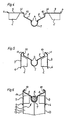
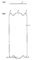
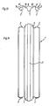
- FIGS. 7 and 8 first show the still flat, undeformed sheet metal blank 1, on the end faces of which two lateral extensions 2 and a central projection 3 each protrude.
- the extensions 2 later serve to form end walls delimiting the end faces of the burner chamber, the extensions 3 and the knobs 4 shown in FIG. 1 serve to hold a cooling tube 5 in a longitudinal trough 7 (FIG. 6).
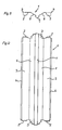
- the extensions 2 are bent approximately perpendicular to the plane of the sheet metal blank 1, as shown in FIGS. 1, 9 and 10, and at the same time the two longitudinal edges 6 of the sheet metal blank 1 are bent into a position inclined to the plane thereof.
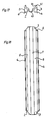
- the trough 7 for the cooling tube 5 is formed by pulling, the same process step also being used on both sides of the trough 7 to serve as the burner plate and to be equipped with the mixture outlet openings stretching inner longitudinal regions 8 are deformed into an inclined position with respect to the outer longitudinal regions 9.
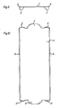
- the third method step comprises pre-bending those edge zones 10 of the inner longitudinal regions 8 which directly adjoin the outer longitudinal regions 9. These edge zones 10 are pre-bent with respect to the edge zones 11 of the two outer longitudinal regions 9 into a position which is initially perpendicular to these longitudinal regions 9.
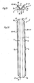
- the fourth method step comprises raising the two outer longitudinal regions 9, which thereby come to lie in a common horizontal plane, the acute angle between the inner longitudinal regions 8 and their edge zones 10 being reduced.
- the two outer longitudinal regions 9 are bent into a position parallel to one another, but do not yet have their desired distance, but an excessively large distance.
- the edge zones 11 of these longitudinal regions 9 are folded, namely in a width which corresponds to the width of the edge zones 10 of the two inner longitudinal regions 8.
- the end wall of the trough 7 for the cooling tube 5 receives a collar 15 formed from the extension 3 of the sheet metal blank 1, which serves for the sealing, and the two inner longitudinal regions 8 with the mixture outlet openings each receive a joint which also serves to seal the end walls of the burner chamber 14 the end extensions 2 of the sheet metal blank 1 sealing flange 16.
- edge zones 10 and 11 of the inner and outer longitudinal regions 8 and 9 are bent inwards together and form a solid both when they lie against each other shielding for the flame area of the burner and a secondary air duct.
Landscapes
- Engineering & Computer Science (AREA)
- Mechanical Engineering (AREA)
- Chemical & Material Sciences (AREA)
- Combustion & Propulsion (AREA)
- General Engineering & Computer Science (AREA)
- Gas Burners (AREA)
- Shaping Metal By Deep-Drawing, Or The Like (AREA)
Applications Claiming Priority (2)
| Application Number | Priority Date | Filing Date | Title |
|---|---|---|---|
| AT247/88 | 1988-02-08 | ||
| AT0024788A AT389248B (de) | 1988-02-08 | 1988-02-08 | Verfahren zur herstellung eines oberteils eines gasbrenners und nach dem verfahren hergestellter gasbrenneroberteil |
Publications (3)
| Publication Number | Publication Date |
|---|---|
| EP0328095A2 true EP0328095A2 (fr) | 1989-08-16 |
| EP0328095A3 EP0328095A3 (en) | 1990-05-16 |
| EP0328095B1 EP0328095B1 (fr) | 1993-06-16 |
Family
ID=3485460
Family Applications (1)
| Application Number | Title | Priority Date | Filing Date |
|---|---|---|---|
| EP19890102223 Expired - Lifetime EP0328095B1 (fr) | 1988-02-08 | 1989-02-08 | Procédé de fabrication d'une tête de brûleur à gaz à partir d'une pièce en tôle découpée |
Country Status (3)
| Country | Link |
|---|---|
| EP (1) | EP0328095B1 (fr) |
| AT (2) | AT389248B (fr) |
| DE (2) | DE3903689A1 (fr) |
Cited By (2)
| Publication number | Priority date | Publication date | Assignee | Title |
|---|---|---|---|---|
| ES2044740A2 (es) * | 1991-05-13 | 1994-01-01 | Fagor S Coop Ltda | Mejoras en quemadores atmosfericos para calentadores de gas y/o similares. |
| CN111964060A (zh) * | 2020-08-06 | 2020-11-20 | 广东合创达电器科技有限公司 | 一种外环火盖及其燃气炉装置 |
Families Citing this family (1)
| Publication number | Priority date | Publication date | Assignee | Title |
|---|---|---|---|---|
| AT397566B (de) * | 1992-05-11 | 1994-05-25 | Vaillant Gmbh | Mischkammeranordnung für brenner und verfahren zur herstellung derselben |
Family Cites Families (6)
| Publication number | Priority date | Publication date | Assignee | Title |
|---|---|---|---|---|
| US3312267A (en) * | 1964-01-13 | 1967-04-04 | Johnson Corp | Gas burner |
| US3499308A (en) * | 1967-03-22 | 1970-03-10 | Tepfer & Sons Inc S | Molding metal |
| FI49248C (fi) * | 1972-07-03 | 1975-05-12 | Valmet Oy | Peltikanavien saumausmenetelmä. |
| DE2434841C2 (de) * | 1974-07-19 | 1976-09-09 | Joh. Vaillant Kg, 5630 Remscheid | Verfahren zur herstellung einer brennerkammer |
| DE8604050U1 (de) * | 1986-02-12 | 1986-06-26 | Joh. Vaillant Gmbh U. Co, 5630 Remscheid | Vormischgasbrenner |
| AT393015B (de) * | 1987-09-21 | 1991-07-25 | Vaillant Gmbh | Gasbrenner |
-
1988
- 1988-02-08 AT AT0024788A patent/AT389248B/de not_active IP Right Cessation
-
1989
- 1989-02-08 AT AT89102223T patent/ATE90786T1/de not_active IP Right Cessation
- 1989-02-08 DE DE3903689A patent/DE3903689A1/de not_active Withdrawn
- 1989-02-08 DE DE8989102223T patent/DE58904669D1/de not_active Expired - Fee Related
- 1989-02-08 EP EP19890102223 patent/EP0328095B1/fr not_active Expired - Lifetime
Cited By (2)
| Publication number | Priority date | Publication date | Assignee | Title |
|---|---|---|---|---|
| ES2044740A2 (es) * | 1991-05-13 | 1994-01-01 | Fagor S Coop Ltda | Mejoras en quemadores atmosfericos para calentadores de gas y/o similares. |
| CN111964060A (zh) * | 2020-08-06 | 2020-11-20 | 广东合创达电器科技有限公司 | 一种外环火盖及其燃气炉装置 |
Also Published As
| Publication number | Publication date |
|---|---|
| DE3903689A1 (de) | 1989-08-17 |
| ATA24788A (de) | 1989-04-15 |
| EP0328095A3 (en) | 1990-05-16 |
| ATE90786T1 (de) | 1993-07-15 |
| AT389248B (de) | 1989-11-10 |
| EP0328095B1 (fr) | 1993-06-16 |
| DE58904669D1 (de) | 1993-07-22 |
Similar Documents
| Publication | Publication Date | Title |
|---|---|---|
| DE69300051T2 (de) | Verbinder für geschweisste Gitter. | |
| DE3428179A1 (de) | Blechkanal-system mit mitteln zum verbinden der enden der einzelnen kanalsektionen sowie eckverbinder zum ausfuehren der verbindungen | |
| EP0309683A1 (fr) | Dispositif de fixation | |
| DE2238858A1 (de) | Waermetauscher insbesondere zur beheizung von fahrzeugen | |
| EP0178430A1 (fr) | Collecteur d'échappement | |
| AT403444B (de) | Verbindung mindestens zweier blechteile | |
| EP0328095B1 (fr) | Procédé de fabrication d'une tête de brûleur à gaz à partir d'une pièce en tôle découpée | |
| DE29704913U1 (de) | Wärmetauscher | |
| DE3110454C2 (de) | Gehäuse für Rohrverteiler | |
| EP1492991A1 (fr) | Echangeur de chaleur soude | |
| DE4120869A1 (de) | Waermetauscher, insbesondere wasser/luft-kuehler fuer verbrennungskraftmaschinen von fahrzeugen | |
| AT395759B (de) | Gasbrenner | |
| DE4025060C2 (de) | Gasbrenner mit einer Brennerkammer und Verfahren zum Herstellen des Oberteiles der Brennerkammer dieses Gasbrenners | |
| EP1348467B1 (fr) | Boîtier en forme de goulotte pour des canaux d'aération et son procédé de fabrication | |
| DE4338959C2 (de) | Wasser/Luft-Wärmetauscher für Kraftfahrzeuge und Herstellungsverfahren für diesen | |
| DE3816688A1 (de) | Flanschverbindung fuer lufttechnischen kanal aus blech und verfahren zur herstellung einer solchen flanschverbindung | |
| DE960107C (de) | Abschirmeinrichtung unter Verwendung von Wellblechtafeln | |
| DE102004012358A1 (de) | Wärmetauscher, insbesondere Ladeluftkühler für ein Kraftfahrzeug | |
| AT397566B (de) | Mischkammeranordnung für brenner und verfahren zur herstellung derselben | |
| AT391198B (de) | Brenner sowie verfahren zur herstellung einer brennerkammer eines solchen brenners | |
| DE2121897B2 (de) | Reihengasbrenner | |
| DE102022108789A1 (de) | Steckverbinder und Steckverbindung | |
| EP0528198B1 (fr) | Lamelle de fixation d'une tôle pliée à un écran à lamelles d'un dispositif d'éclairage | |
| DE10053875C1 (de) | Brennerplatte für einen Gasbrenner | |
| EP1375309B1 (fr) | Partie de structure jointe avec deux tôles adjacentes |
Legal Events
| Date | Code | Title | Description |
|---|---|---|---|
| PUAI | Public reference made under article 153(3) epc to a published international application that has entered the european phase |
Free format text: ORIGINAL CODE: 0009012 |
|
| AK | Designated contracting states |
Kind code of ref document: A2 Designated state(s): AT BE CH DE ES FR GB GR IT LI LU NL SE |
|
| PUAL | Search report despatched |
Free format text: ORIGINAL CODE: 0009013 |
|
| AK | Designated contracting states |
Kind code of ref document: A3 Designated state(s): AT BE CH DE ES FR GB GR IT LI LU NL SE |
|
| 17P | Request for examination filed |
Effective date: 19901108 |
|
| 17Q | First examination report despatched |
Effective date: 19910902 |
|
| RAP1 | Party data changed (applicant data changed or rights of an application transferred) |
Owner name: VAILLANT GMBH Owner name: VAILLANT B.V. Owner name: VAILLANT LTD. Owner name: VAILLANT GES.M.B.H Owner name: VAILLANT S.A.R.L Owner name: N.V. VAILLANT S.A. Owner name: JOH. VAILLANT GMBH U. CO. |
|
| GRAA | (expected) grant |
Free format text: ORIGINAL CODE: 0009210 |
|
| AK | Designated contracting states |
Kind code of ref document: B1 Designated state(s): AT BE CH DE ES FR GB GR IT LI LU NL SE |
|
| PG25 | Lapsed in a contracting state [announced via postgrant information from national office to epo] |
Ref country code: SE Effective date: 19930616 Ref country code: GR Free format text: LAPSE BECAUSE OF FAILURE TO SUBMIT A TRANSLATION OF THE DESCRIPTION OR TO PAY THE FEE WITHIN THE PRESCRIBED TIME-LIMIT Effective date: 19930616 Ref country code: ES Free format text: THE PATENT HAS BEEN ANNULLED BY A DECISION OF A NATIONAL AUTHORITY Effective date: 19930616 Ref country code: BE Effective date: 19930616 |
|
| REF | Corresponds to: |
Ref document number: 90786 Country of ref document: AT Date of ref document: 19930715 Kind code of ref document: T |
|
| ITF | It: translation for a ep patent filed | ||
| REF | Corresponds to: |
Ref document number: 58904669 Country of ref document: DE Date of ref document: 19930722 |
|
| GBT | Gb: translation of ep patent filed (gb section 77(6)(a)/1977) |
Effective date: 19930628 |
|
| RAP4 | Party data changed (patent owner data changed or rights of a patent transferred) |
Owner name: VAILLANT GMBH Owner name: VAILLANT B.V. Owner name: VAILLANT LTD. Owner name: VAILLANT GES.M.B.H Owner name: VAILLANT S.A.R.L Owner name: N.V. VAILLANT S.A. Owner name: JOH. VAILLANT GMBH U. CO. |
|
| ET | Fr: translation filed | ||
| PGFP | Annual fee paid to national office [announced via postgrant information from national office to epo] |
Ref country code: FR Payment date: 19931201 Year of fee payment: 6 |
|
| PGFP | Annual fee paid to national office [announced via postgrant information from national office to epo] |
Ref country code: GB Payment date: 19931206 Year of fee payment: 6 |
|
| PGFP | Annual fee paid to national office [announced via postgrant information from national office to epo] |
Ref country code: DE Payment date: 19931228 Year of fee payment: 6 |
|
| PGFP | Annual fee paid to national office [announced via postgrant information from national office to epo] |
Ref country code: AT Payment date: 19940121 Year of fee payment: 6 |
|
| PG25 | Lapsed in a contracting state [announced via postgrant information from national office to epo] |
Ref country code: LU Free format text: LAPSE BECAUSE OF NON-PAYMENT OF DUE FEES Effective date: 19940228 Ref country code: LI Effective date: 19940228 Ref country code: CH Effective date: 19940228 |
|
| PLBE | No opposition filed within time limit |
Free format text: ORIGINAL CODE: 0009261 |
|
| STAA | Information on the status of an ep patent application or granted ep patent |
Free format text: STATUS: NO OPPOSITION FILED WITHIN TIME LIMIT |
|
| 26N | No opposition filed | ||
| PG25 | Lapsed in a contracting state [announced via postgrant information from national office to epo] |
Ref country code: NL Effective date: 19940901 |
|
| NLV4 | Nl: lapsed or anulled due to non-payment of the annual fee | ||
| REG | Reference to a national code |
Ref country code: CH Ref legal event code: PL |
|
| PG25 | Lapsed in a contracting state [announced via postgrant information from national office to epo] |
Ref country code: GB Effective date: 19950208 Ref country code: AT Effective date: 19950208 |
|
| GBPC | Gb: european patent ceased through non-payment of renewal fee |
Effective date: 19950208 |
|
| PG25 | Lapsed in a contracting state [announced via postgrant information from national office to epo] |
Ref country code: FR Effective date: 19951031 |
|
| PG25 | Lapsed in a contracting state [announced via postgrant information from national office to epo] |
Ref country code: DE Effective date: 19951101 |
|
| REG | Reference to a national code |
Ref country code: FR Ref legal event code: ST |
|
| PG25 | Lapsed in a contracting state [announced via postgrant information from national office to epo] |
Ref country code: IT Free format text: LAPSE BECAUSE OF NON-PAYMENT OF DUE FEES;WARNING: LAPSES OF ITALIAN PATENTS WITH EFFECTIVE DATE BEFORE 2007 MAY HAVE OCCURRED AT ANY TIME BEFORE 2007. THE CORRECT EFFECTIVE DATE MAY BE DIFFERENT FROM THE ONE RECORDED. Effective date: 20050208 |