EP0328260A2 - Stossisoliertes tragbares Massenspeichergerät - Google Patents
Stossisoliertes tragbares Massenspeichergerät Download PDFInfo
- Publication number
- EP0328260A2 EP0328260A2 EP89300579A EP89300579A EP0328260A2 EP 0328260 A2 EP0328260 A2 EP 0328260A2 EP 89300579 A EP89300579 A EP 89300579A EP 89300579 A EP89300579 A EP 89300579A EP 0328260 A2 EP0328260 A2 EP 0328260A2
- Authority
- EP
- European Patent Office
- Prior art keywords
- canister
- mass storage
- storage device
- chassis
- pins
- Prior art date
- Legal status (The legal status is an assumption and is not a legal conclusion. Google has not performed a legal analysis and makes no representation as to the accuracy of the status listed.)
- Ceased
Links
Images


Classifications
-
- G—PHYSICS
- G11—INFORMATION STORAGE
- G11B—INFORMATION STORAGE BASED ON RELATIVE MOVEMENT BETWEEN RECORD CARRIER AND TRANSDUCER
- G11B33/00—Constructional parts, details or accessories not provided for in the other groups of this subclass
- G11B33/12—Disposition of constructional parts in the apparatus, e.g. of power supply, of modules
- G11B33/121—Disposition of constructional parts in the apparatus, e.g. of power supply, of modules the apparatus comprising a single recording/reproducing device
- G11B33/122—Arrangements for providing electrical connections, e.g. connectors, cables, switches
-
- G—PHYSICS
- G11—INFORMATION STORAGE
- G11B—INFORMATION STORAGE BASED ON RELATIVE MOVEMENT BETWEEN RECORD CARRIER AND TRANSDUCER
- G11B33/00—Constructional parts, details or accessories not provided for in the other groups of this subclass
- G11B33/02—Cabinets; Cases; Stands; Disposition of apparatus therein or thereon
- G11B33/022—Cases
- G11B33/025—Portable cases
-
- G—PHYSICS
- G11—INFORMATION STORAGE
- G11B—INFORMATION STORAGE BASED ON RELATIVE MOVEMENT BETWEEN RECORD CARRIER AND TRANSDUCER
- G11B33/00—Constructional parts, details or accessories not provided for in the other groups of this subclass
- G11B33/02—Cabinets; Cases; Stands; Disposition of apparatus therein or thereon
- G11B33/08—Insulation or absorption of undesired vibrations or sounds
-
- G—PHYSICS
- G11—INFORMATION STORAGE
- G11B—INFORMATION STORAGE BASED ON RELATIVE MOVEMENT BETWEEN RECORD CARRIER AND TRANSDUCER
- G11B33/00—Constructional parts, details or accessories not provided for in the other groups of this subclass
- G11B33/12—Disposition of constructional parts in the apparatus, e.g. of power supply, of modules
- G11B33/121—Disposition of constructional parts in the apparatus, e.g. of power supply, of modules the apparatus comprising a single recording/reproducing device
- G11B33/123—Mounting arrangements of constructional parts onto a chassis
- G11B33/124—Mounting arrangements of constructional parts onto a chassis of the single recording/reproducing device, e.g. disk drive, onto a chassis
Definitions
- This invention generally relates to the field of mass data storage devices (e.g. disk drives) of the type which are removably mounted within a computer chassis as part of an overall data storage system. It more specifically relates to a shock isolated mass data storage system which significantly minimizes the risk of data being lost due to head crashing, for example when the system is removed from the computer chassis .
- the shock isolated mass storage device may also include a sub system which automatically disables the power supply to the mass storage device in response to its removal from the computer chasis - yet prior to its actual physical disconnection therefrom while also effecting delayed application of power to the drive upon insertion into the chassis,
- Mass storage devices such as, hard disk drives, optical disk drives and the like, are well known components of an overall computer data storage system Mass storage an its have, in the past, usually been bolted and hardwired inside a computer chassis and were only removed from the c!assis (wit!′ significant effort) in the event of needed maintenance or the device's failure,
- mass storage devices which are in the form of modular units capable of being operatively and easily removably mounted within a computer chassis. Due to their modular nature, these portable individual mass storage devices are particularly useful when dedicated to the storage of important data which the user does not wish to be continuously in operative association with the computer for security and/or data integrity reasons. These individual portable mass storage devices can thus be removed easily from the computer chassis and stored in a secured location remote from the computer site until the data is needed, at which time the mass storage device is retrieved, transported and operatively reinstalled within the computer chassis (as by sliding the mass storage device into a "slot" in the computer chassis). In such a manner, the risks associated with unauthorized persons intentionally tampering, copying, or stealing the stored data (with the possible disastrous loss of valuable data) and/or unintentional data loss is minimized,
- Mass storage devices have included in the past mechanical means which locks the read/write head during transport, in addition to special software-controlled mechanical interlocks (e.g., which parks the head at a "storage" position and/or at a section of the disk on which no data is stored) as protective measures in an attempt to prevent head crash and data loss due to shock waves experienced by mishandling the mass data storage device.
- these conventional protective mechanical and software systems are usually insufficient in the case of severe shock waves (as when the mass storage device is dropped onto a surface). And, in any event, such mishandling may damage other shock sensitive components of the mass storage device (e.g., precision motors, control circuitry, etcetera)
- Mass storage devices including the more recently developed portable Versions, have in the past been shock-isolated when operatively associated with the computer's chassis (see, for example, U S, Patent No. 4,705,257, t:e entire disclosure of which is expressly incorporated hereinto by reference), while shock-isolation of the mass storage device is important when it is operatively associated within the computer's chassis, it is equally (if not more) important for the device to be shock-isolated while removed from the chassis and while being transported to a different location,
- FIGURE 1 Such a canister/drive assembly l is schematically shown in accompanying FIGURE 1 and is generally representative of the Series 3000 and 4000 systems previously sold by MDB Systems, Inc, (the Assignee of this application).
- the assembly 1 includes a canister 2 defining an interior space 2a in which a drive 3 was mounted for shock and vibration isolation via three substantially hemispherical elastomer isolators 4.
- the canister 2 was slidably received within a computer chassis 5 so that it could easily be removed therefrom (as indicated by the dashed line representation).
- the isolators 4 were positioned in a trilateral arrangement relative to the drive 3 that is, two of the isolators 4 were positioned between respective sides of the drive 3 and an adjacent portion of the canister 2, while the remaining isolator 4 was positioned between the front of the drive 3 and an adjacent front portion of the canister 2.
- This third isolator provides both tension and compression shock isolation forces and thus can, in effect, be considered as equivalent to a pair of isolators, one located at each end of drive 3.
- the canister/drive assembly 1 shown in FIGURE 1 shock a d vibration isolates the drive 3 at all times during operation and transport, it is too costly for most removable mass data storage applications and tends to use a lot of internal space in the removable module 2 since the isolators 4 located on at least three sides of drive 3 consume space greatly in excess of the needed "sway space.”
- the canister/drive assembly I tended to be cost and space effective only for those applications in which the shock and vibration isolation functions were an absolute necessity (i.e., as in military field computer applications) and where sufficient excess space is available. What has still been needed therefore, is a shock isolation mounting system for removable drives which is less costly and more space efficient so that general consumer computers may, for example, have shock protected removable drive modules. It is towards fulfilling this need that the present invention is directed.
- a mass storage device (which shall be hereinafter simply be termed "drive” for ease of reference) is provided in a portable canister which is sized and configured to be mounted removably and operatively within the chassis of a computer. Shock-isolation of the drive is provided through a pair of brackets rigidly mounted to respective lateral sides of the drive. Each of the brackets includes a pair of elastomeric shock-isolators connected to, and extending between, itself and an adjacent sidewall of the canister. The front and rear ends of the drive are thus left freely floating within the canister so tl at only the requisite "sway space” need be left at these locations (thus maximizing space efficiency).
- the drive thus is mounted within, and in spaced relation to, the canister so that shock waves experienced by the canister/drive assembly wi11 be absorbed by the elastomeric shock isolators and thus significantly minimize the risk oi head crash during its transport -- while yet remaining very economical and space efficient.
- the canister also preferably houses a printed circuit board which is electrically coupled to the drive via any suitable conventional means (e.g., multiwire ribbon connectors, and the like).
- the printed circuit board may itself be mounted to the canister by means of elastomeric feet allowing the board to "float" (i.e., be resiliently displaced) when the canister/drive assembly is slid into operative engagement with the computer chassis so as to permit the pin connectors of the board to passively align with female connectors in the chassis,
- shock isolation of tle drive is provided at all times during the drive's physical transport from one location to another -- even when it is disassociated from the computer chassis,
- the removable nature of the canister/drive assembly of the invention presents a risk that the power supply (normally remaining with the chassis when the canister/drive is removed) will not be manually turned off by the user before the canister/drive is removed as it should always be. Conversely, the user may forget to turn the chassis power off prior to the canister/drive being reinserted into the chassis. Either condition could cause arcing between the connector pins of the cannister and their associated female connectors of the chassis and/or possible head/disk surface damage,
- the present invention further includes a protective system for sensing relative separable movement between the male and female connectors and, in response to this sensed movement, to disable the power supply before the male and female connectors actually physically separate.
- the protective system functions to supply power to the mass storage device only after the pins of the male connector have electrically connected with their respective female connectors,
- the sensing and disabling functions of the protective system briefly mentioned above are achieved by control circuitry associated with at least one pin of a multiple pin connector which is shorter in length as compared to the other co;:nector pins.
- the shorter pin(s) is(are) the first to "break” and the last to "make” contact with its (their) female connector(s) (i.e., as compared to the longer pins) during removal/insertion of the canister drive assembly
- the control circuitry thus serves to ensure that the power supply is switched off/on only while the longer pins are in physical and electrical contact with their female connectors during removal/insertion of the canister/drive assembly relative to the chassis,
- a computer data storage system 10 is shown in accompanying FIGURE 2 as including chassis 12 having individual locations for slidably and removably receiving multiple individual canisters 14.
- the interior of chassis 12 is preferably provided with a pair of spaced-apart guides 12a which slidably receive a respective one of the rails 14a rigidly mounted to the side of canister 14 (only one such rail 14a being visible in FIGURE 2).
- the canisters 14 may be disassociated from chassis 12 (as by manually pulling them out of their operative association with chassis 12) so as to permit each canister 14 to physically be transported to a different location, as may be desired.
- a front panel 12c may be pivoted into covering relationship to the canisters 14 so that power switches, status LED'S and the like (not shown in FIGURE 1, but see FIGURE 9) may be visible to the user.
- the chassis 12 is provided with a rear compartment 12b for housing the usual power supply, control circuitry, signal processing circuitry, etcetra, which are collectively identified in FIGURE 2 by reference numeral 31 and will hereinafter be simply reierred to as "power/control circuitry 31",
- An exemplary canister 14 is shown more clearly in FIGURES 3-5 as including a mass storage device, which in the embodiment shown is a disk drive 16, mounted within canister housing 18
- the canister housing 18 is preferably closed at its top by means of a cover 19 (see FIGURE 2), but is shown in FIGURES 3 and 5 with the cover 19 removed for clarity of presentation Vents 20 are provided in the rear wall 22 of canister housing 18 so as to permit the drive 16 to be air cooled by means of a conventional fan (not shown).
- the drive 16 is thus bounded by the canister's opposed rear and front walls 22, 24, respectively, and its opposing pair of side walls 26, 28.
- a handle 29 is pivotally affixed to the front edge regions of side walls 26 and 28 adjacent the front wall 28 so as to more easily permit manual removal/insertion of assembly 14 from/into chassis 12 and its transport to/from a remote location,
- a printed circuit board 30 is mounted to the interior surface of the rear wall 22 by means of bolts 32 which serve to hold the board 30 against resilient, elastomeric mounting feet 34 in spaced relation to the interior surface of the rear wall 22.
- the mounting feet 34 permit the board 30 to be resiliently displaced within the board's plane so as to cause the pins 35 of male connector 36 associated with the board 30 to be aligned and mated with respective sleeves 37 of female connector 38 (associated with the computer chassis 12 When canister 14 is slid into operative engagement within the chassis 12, see FIGURE 2) thereby establishing electrical communication between the drive 16 and the power/control circuitry 31 (see FIGURE 2).
- Shock isolation of the drive 16 is provided, according to this invention, by means of a pair of shock-isolation assemblies 42 disposed along each respective lateral side of the drive 16.
- the assemblies 42 are shown more specifically in accompanying FIGURES 5 and 6.
- FIGURE 6 although showing only one assembly 42, is likewise representative of the other assembly 42.
- assembly 42 includes a mounting bracket 44 which preferably includes an integral perpendicular flange 44a for structural reinforcement purposes,
- Paired apertures 46, 48 are provided in bracket 44 in a location which corresponds to the industry standard thread sites associated with the drive 16. That is, the aperture pairs 46, 48 are each separated by an industry standard dimension X f and are, in turn, assymetrically disposed relative to the drive's midplane. The paired apertures 46, 48 thus accept mounting screws so as to rigidly mount the bracket flus!1 against the lateral sides of drive 16. As can be appreciated, when the bracket 44 is installed on the lefthand side of drive 16 (as viewed in FIGURE 3) then the aperture pair 46 is employed since they will then be aligned with the industry-standard thread sites associated with drive 16. On the other hand, when the bracket 44 is installed on the righthand side of drive 16 (as viewed in FIGURE 3), the other aperture pair 48 will then be employed since they will then be in alignment with the industry-standard thread sites on that side,
- a pair of shock-isolators 50 are mounted to the bracket 44 at locations along the linear extent, and closely adjacent respective terminal ends, of the bracket 44 so that the isolators 50 are, insofar as possible, approximately symmetrically disposed about the center of gravity of the drive 16 (the exact location of the center of gravity may vary from one type drive to the next).
- Each isolator 50 is preferably provided with a mounting flange 52 defining an opposing pair of apertures 52a through which mounting bolts 54 pass so that nut/washer means 56 can be threaded upon their respective bolt's shaft to securely mount each isolator 50 against its respective bracket 44.
- the shock isolators 50 are also provided with a mounting nipple 58 (preferably formed of metal) which defines a threaded bore 58a in which mounting bolts 60 (see FIGURE 3) may be threadably coupled so as to secure the nipple 58 (and hence the isolator 50 with which it is associated) to a respective sidewall of canister housing 18.
- a mounting nipple 58 preferably formed of metal
- mounting bolts 60 see FIGURE 3
- An elastomeric body 62 extends between flange 52 and nipple 58.
- the body 62 preferably is formed of a generally cylindrical rearward (i.e., towards the drive 16) wall portion 64 and an integral forward i.e., towards the sidewall of the canister 18) generally truncated conical wall portion 66.
- the flange 52 is coupled to cylindrical wall portion 64
- the nipple 58 is coupled to the truncated end of conical wall portion 66.
- shock-isolator 50 generally described above and shown in the accompanying drawings is commercially available from Barry Control of Burbank, California, Model No. ME 500-4. However, other geometric configurations and elastomeric materials may be employed, the particular selection being dependant upon a number of design and performance criteria, such as the overall dimensions of the isolator, its shock absorbing characteristics and the like. Any such isolator should exhibit a minimum performance characteristic such that a "sway space" of about .40 inch is provided for the drive 16.
- sway space is meant the maximum dimensional displacement of drive 16 within canister housing 18 at which the isolators SC absorb substantially all of the shock waves causing such displacement and hence effective)y shock isolate the drive 16.
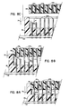
- FIGURES 8a 8c The male and female connectors 36, 38, respectively, of this invention are shown more clearly in FIGURES 8a 8c
- the male connector 36 is provided with multiple length pins, the shorter pins being designated by reference numeral 35a, and the longer pins being designated by reference numeral 35b
- FIGURE 8a is shown in a state where the male connector 36 has begun to separate from the female connector 38 (as occurs when a user mannually removes the canister/drive 14/16 from chassis 12 in the direction of arrow 74) but the shorter and longer pins 35a and 35b are still in physical contact with their respective conductive sleeves 37a and 37b of female connector 38, respectively.
- the shorter pins 35a are the first to break and the last to make contact with the female connector 38 as compared to the longer pins 35b when the canister 14 is removed from and inserted into the chassis 12, respectively
- no extra electro mechanical switches are required to provide fail-safe automatic head par):ing or to prevent contact arcing or to insure connection of all power and signal connectors before power is actually supplied to the drive
- the result is a particularly cost-effective fail safe system that is relatively simple to realize
- the dimension "d" by which the length of the pins 35a are shorter than the pins 35b (and which, in the preferred embodiment, is about 2 mm) effectively functions as a sensor which will initiate the protective control circuitry of this invention
- dimension "d" (coupled with the protective control circuitry to be described below) will cause the power supplied to the longer pins 35b to drop to substantially zero volts before they break electrical contact. This abrupt voltage drop also will typically cause the inherent protective system of many drives 16 to, for example, initiate head protection circuitry so as to quickly park the heads in proper zones relative to the data storage medium.
- FIGURE 9 is a schematic diagram of an exemplary protective control circuitry and is shown in a state whereby the canister/drive 14/16 assembly is operatively associated with the chassis 12 (not shown in FIGURE 9) by mated interconnection of t!′e male and female connectors 36 and 38.
- power in the form of +12 and +5 volts is supplied though field effect transistor (FET) switches 76, 78 to respective sleeve/pins 37b/35b of the female and male connectors 38 and 36, respectively,
- FET field effect transistor
- a user need only depress momentary switch 79 (e.g., located on front panel 12c) so as to provide a clock input (via debounce circuit 81) to flip flop 84.
- momentary switch 79 e.g., located on front panel 12c
- the synchronous input "D" is being supplied with logic "0" from the Q output of flip flop 84 thereby causing the Q and Q outputs to reverse -- that is, Q becomes logic "0” (thereby illuminating the red LED via inverter 85) and Q becomes logic "1” (thereby extinguishing the green LED via inverter 86).
- the logic “1" from the Q output is supplied as an input to inverter 88 which thus outputs logic “0” turning the FET switches on and enabling power to be supplied to the canister/drive 14/16 via pins/sleeves 35b/37b, respectively,
- the logic “0" from the Q output is also supplied as an input to inverter 88 thereby supplying a logic “1” to disable FET switches 76, 78 and remove power from the drive.
- the Q output of flip-flop 84 becomes, of course, logic "1” thereby extinguishing the red LED via inverter 85,
- the male and female connectors 36 and 38 may be shunted such that power is automatically supplied to canister/drive 14/16 in response to its being installed in the computer chassis 12.
- the preset input PS to flip-flop 84 has no effect on the logic functions described above. If, on the other hand, a user desires to have the power initiated only in response to installation of canister/drive 14/16 in chassis 12, then the user simply jumpers plugs C and D together and opens plugs A and B thereby rendering switch 79 inoperable
Landscapes
- Details Of Connecting Devices For Male And Female Coupling (AREA)
- Casings For Electric Apparatus (AREA)
- Mounting Of Printed Circuit Boards And The Like (AREA)
Applications Claiming Priority (2)
| Application Number | Priority Date | Filing Date | Title |
|---|---|---|---|
| US159536 | 1988-02-12 | ||
| US07/159,536 US4937806A (en) | 1988-02-12 | 1988-02-12 | Shock-isolated portable mass data storage device |
Publications (2)
| Publication Number | Publication Date |
|---|---|
| EP0328260A2 true EP0328260A2 (de) | 1989-08-16 |
| EP0328260A3 EP0328260A3 (de) | 1990-02-07 |
Family
ID=22572967
Family Applications (1)
| Application Number | Title | Priority Date | Filing Date |
|---|---|---|---|
| EP89300579A Ceased EP0328260A3 (de) | 1988-02-12 | 1989-01-20 | Stossisoliertes tragbares Massenspeichergerät |
Country Status (5)
| Country | Link |
|---|---|
| US (1) | US4937806A (de) |
| EP (1) | EP0328260A3 (de) |
| JP (1) | JPH01243287A (de) |
| CA (1) | CA1334308C (de) |
| DE (1) | DE328260T1 (de) |
Cited By (17)
| Publication number | Priority date | Publication date | Assignee | Title |
|---|---|---|---|---|
| EP0381408A1 (de) * | 1989-01-31 | 1990-08-08 | International Business Machines Corporation | Gerät mit Magnetplatten |
| GB2241118A (en) * | 1990-02-15 | 1991-08-21 | Ibm | Electrical apparatus with forced air cooling |
| WO1992018979A1 (de) * | 1991-04-22 | 1992-10-29 | Ibsm Mehltretter Gmbh | Verpackungseinrichtung für magnetbandwickel |
| WO1993001599A1 (de) * | 1991-07-13 | 1993-01-21 | Tappert Karl Heinz | Lagerung für ein festplattenlaufwerk oder dgl. |
| US5193050A (en) * | 1990-07-03 | 1993-03-09 | International Business Machines Corporation | Enclosure for electronic subsystems in a data processing system |
| US5224020A (en) * | 1990-04-18 | 1993-06-29 | International Business Machines Corporation | Electronic apparatus having modular front and back functional units and electrical distribution unit including a fan therebetween |
| EP0488679A3 (en) * | 1990-11-30 | 1993-08-04 | Fujitsu Limited | Storage disk module and storage disk device having a plurality of storage disk modules |
| EP0570138A3 (de) * | 1992-05-12 | 1994-10-19 | Ibm | Tragbares Plattenspeichergerät. |
| EP0673035A3 (de) * | 1994-03-15 | 1996-05-29 | Hitachi Ltd | Magnetplattenantriebsvorrichtung. |
| GB2299436A (en) * | 1995-03-31 | 1996-10-02 | Teng Chun Chen | A removable disk drive with pivoting handle |
| EP0814477A3 (de) * | 1996-06-20 | 1998-05-06 | Mitsumi Electric Company Ltd. | Platteneinheit |
| EP0892336A1 (de) * | 1997-07-15 | 1999-01-20 | Sun Microsystems, Inc. | Computergehäuse |
| GB2342759A (en) * | 1998-10-10 | 2000-04-19 | Pti Limited | Data cartridge assembly with vibration damping |
| US6671124B2 (en) * | 2001-09-07 | 2003-12-30 | Lockheed Martin Corporation | Shock and vibration system |
| US6925246B1 (en) | 2000-07-05 | 2005-08-02 | Steinbeck Cannery, Llc | Television recorder having a removeable hard disk drive |
| WO2007046900A1 (en) * | 2005-10-17 | 2007-04-26 | Hewlett-Packard Development Company, L.P. | Protective data storage caddy |
| EP1163570A4 (de) * | 1999-02-19 | 2007-12-19 | Gen Dynamics Inf Systems Inc | Gehäuse für datenspeicherung |
Families Citing this family (104)
| Publication number | Priority date | Publication date | Assignee | Title |
|---|---|---|---|---|
| USRE34369E (en) * | 1987-10-01 | 1993-09-07 | Adapter and a removable slide-in cartridge for an information storage system | |
| JPH01260660A (ja) * | 1988-04-11 | 1989-10-17 | Toshiba Corp | 情報処理装置 |
| IT1217801B (it) * | 1988-06-08 | 1990-03-30 | Honeywell Rull Italia S P A | Apparato per rimozione/inserzione a caldo su un bus di connessione di unita, di registrazione magnetica a supporto non rimovibile |
| JPH087993B2 (ja) * | 1988-06-09 | 1996-01-29 | 富士電機株式会社 | 磁気ディスク装置 |
| JPH0221381A (ja) * | 1988-07-11 | 1990-01-24 | Canon Inc | データ通信システム |
| FR2634341B1 (fr) * | 1988-07-13 | 1990-09-14 | Bull Sa | Systeme de connexion electrique d'un ordinateur |
| US5123004A (en) * | 1988-07-17 | 1992-06-16 | 501 Nakamichi Corporation | Recording and/or reproducing apparatus having a vertically movable disk chassis and arranged to prevent external forces from disrupting proper operations |
| US5163038A (en) * | 1988-07-17 | 1992-11-10 | Nakamichi Corporation | Recording and/or reproducing apparatus with vibration isolation means |
| US5042024A (en) * | 1989-04-28 | 1991-08-20 | Pioneer Electronic Corporation | Disk reproduction apparatus capable of being disposed in different attitudes |
| FR2652940B1 (fr) * | 1989-10-05 | 1994-03-11 | Bull Sa | Dispositif de fixation de peripheriques d'ordinateur. |
| GB2241101A (en) * | 1990-02-15 | 1991-08-21 | Ibm | Data storage system with device dependent flow of cooling air |
| US5212681A (en) * | 1990-07-02 | 1993-05-18 | Storage Technology Corporation | Cartridge positioning and interlock apparatus |
| US5155662A (en) * | 1991-01-16 | 1992-10-13 | Shou Tsai I | Hard disc drive mounting structure |
| JP3006724B2 (ja) * | 1991-02-22 | 2000-02-07 | ソニー株式会社 | 取付装置 |
| US5233594A (en) * | 1991-05-02 | 1993-08-03 | Wilhelm Joseph R | Easily installable removable integrated hard disk and controller |
| US5426564A (en) * | 1991-09-30 | 1995-06-20 | Hsu; Winston | Modular electronic packaging |
| US5430617A (en) * | 1991-09-30 | 1995-07-04 | Hsu; Winston | Modular electronic packaging for internal I/O modules |
| JP3053031B2 (ja) * | 1991-10-29 | 2000-06-19 | 三菱電機株式会社 | 防振装置 |
| KR100267163B1 (ko) * | 1991-11-15 | 2001-04-02 | 제이 엘. 차스킨, 버나드 스나이더, 아더엠. 킹 | 래크에 설치가능한 섀시 인클로우져 |
| AU3421593A (en) * | 1991-12-23 | 1993-07-28 | Elf Atochem North America, Inc. | Multi-mode accelerometer |
| US5187643A (en) * | 1992-02-04 | 1993-02-16 | Shou Tsai I | Computer mounting structure for a detachable hard disk drive |
| DE69319260T2 (de) * | 1992-02-06 | 1998-12-17 | Pioneer Electronic Corp., Tokio/Tokyo | Schwingungsdämpfender Aufhängemechanismus für Wiedergabegerät von aufgezeichneten Daten |
| US5454080A (en) * | 1992-02-10 | 1995-09-26 | International Business Machines Corporation | Removable hard disk drive system with circuit for hot insertion and removal responsive to contacts of zero-insertion-force connector on the lateral side of the drive |
| US5223996A (en) * | 1992-03-20 | 1993-06-29 | Digital Equipment Corporation | Combined shock mount frame and seal for a rigid disk drive |
| US5400196A (en) * | 1992-04-30 | 1995-03-21 | International Business Machines Corporation | DASD with spindle imbalance isolation and method for producing same |
| US5333097A (en) * | 1992-06-18 | 1994-07-26 | Digital Equipment Corporation | Disk drive holder and interconnection system |
| US5289348A (en) * | 1992-11-19 | 1994-02-22 | Harold R. Miller | Shock absorbing rack system |
| US5430607A (en) * | 1992-12-31 | 1995-07-04 | North Atlantic Industries, Inc. | Rugged modular portable computer including modules hinged along an edge |
| US5726922A (en) * | 1994-01-03 | 1998-03-10 | International Business Machines Corp. | Assembly for removably connecting data storage devices |
| US5486982A (en) * | 1994-06-10 | 1996-01-23 | Hsu; Winston | Modular electronic packaging for computer servers |
| US5557739A (en) * | 1994-11-14 | 1996-09-17 | Gateway 2000, Inc. | Computer system with component removal and replacement control scheme |
| MY114912A (en) | 1994-12-22 | 2003-02-28 | Ibm | Removable electronic subassembly with a compressible shock absorbing device |
| US5668697A (en) * | 1995-04-20 | 1997-09-16 | Hewlett-Packard Company | Data storage module having cradles on housing and elastomeric member mounted on data storage mechanism |
| US5917795A (en) * | 1995-04-28 | 1999-06-29 | Mitsumi Electric Co., Ltd. | Disk device having a drive unit and a cam plate which moves up and down relative to a disk holder for providing a thin structure |
| US5751551A (en) * | 1995-11-07 | 1998-05-12 | Sun Microsystems, Inc. | Universal hard drive bracket with shock and vibrational isolation and electrical grounding |
| US5768097A (en) * | 1996-04-26 | 1998-06-16 | Server Systems Technology, Inc. | Reconfigurable modular computer assembly having a main chassis with a removably attached face plate and at least one spacer removably attached to the face plate |
| JPH10222972A (ja) * | 1997-02-05 | 1998-08-21 | Matsushita Electric Ind Co Ltd | 記憶装置、及びそれに用いる耐衝撃用収納容器 |
| DE19708775C1 (de) * | 1997-03-04 | 1998-07-02 | Siemens Nixdorf Inf Syst | Trägeranordnung für elektronische Baugruppen |
| US6002588A (en) * | 1997-12-04 | 1999-12-14 | Lockheed Martin Corporation | Thermally conductive vibration isolators |
| US6308059B1 (en) | 1997-12-12 | 2001-10-23 | Joseph Domes | Ruggedized tradesworkers radio |
| US6015196A (en) * | 1998-03-26 | 2000-01-18 | Pacific Micro Data, Inc. | Module mounting system |
| CN1867068A (zh) | 1998-07-14 | 2006-11-22 | 联合视频制品公司 | 交互式电视节目导视系统及其方法 |
| US6022224A (en) * | 1998-07-22 | 2000-02-08 | International Business Machines Corporation | Shock mount connector for head disk assembly |
| US6229780B1 (en) * | 1998-09-30 | 2001-05-08 | Acer Peripherals, Inc. | Case mounting for external suspending CD drive |
| US6122164A (en) * | 1998-10-16 | 2000-09-19 | Dell Usa, L.P. | Shock absorbing spacers for portable computer hard disc drives |
| US6097608A (en) * | 1998-11-16 | 2000-08-01 | International Business Machines Corporation | Disk drive vibration isolation using diaphragm isolators |
| US6325353B1 (en) * | 1999-03-08 | 2001-12-04 | Intel Corporation | Carrier for disk drive hot swapping |
| US6233147B1 (en) * | 1999-06-03 | 2001-05-15 | Micron Electronics | Apparatus for securing a component in a computer chassis |
| US6359836B1 (en) * | 1999-06-09 | 2002-03-19 | Hewlett-Packard Company | Locking isolation mounting system for data storage modules |
| US6203130B1 (en) * | 1999-06-21 | 2001-03-20 | Hubbell Incorporated | Enhanced telecommunications cabinet assembly having movable wiring interconnect management tray removably supporting modular interconnect panels |
| US6999909B1 (en) | 1999-10-28 | 2006-02-14 | Seagate Technology Llc | Process for designing an optimal vibration isolation mount for a disc drive |
| US6477042B1 (en) * | 1999-11-18 | 2002-11-05 | Siemens Energy & Automation, Inc. | Disk drive mounting system for absorbing shock and vibration in a machining environment |
| US6437939B1 (en) * | 2000-01-19 | 2002-08-20 | International Business Machines Corporation | Ergonomic safety assist mechanism for handling micro-sized computer hard disk drives |
| EP1126360B1 (de) * | 2000-02-14 | 2003-11-12 | Hewlett-Packard Company, A Delaware Corporation | Tischrechnergerät |
| US6628474B1 (en) | 2000-06-09 | 2003-09-30 | Iomega Corporation | Method and apparatus for electrostatic discharge protection in a removable cartridge |
| US6633445B1 (en) | 2000-06-09 | 2003-10-14 | Iomega Corporation | Method and apparatus for electrically coupling components in a removable cartridge |
| US6717762B1 (en) | 2000-06-09 | 2004-04-06 | Iomega Corporation | Method and apparatus for making a drive compatible with a removable cartridge |
| US6624979B1 (en) | 2000-06-09 | 2003-09-23 | Iomega Corporation | Method and apparatus for parking and releasing a magnetic head |
| US6687837B1 (en) * | 2000-06-15 | 2004-02-03 | Cisco Technology, Inc. | Method and system for controlling the supply of power to a circuit card in a card shelf through an activation signal |
| ES2312475T3 (es) | 2000-10-11 | 2009-03-01 | United Video Properties, Inc. | Sistemas y metodos para proporcionar el almacenamiento de datos en servidores de un sistema de entrega de medios bajo demanda. |
| US6781782B2 (en) | 2000-12-21 | 2004-08-24 | Iomega Corporation | Method and apparatus for saving calibration parameters for a removable cartridge |
| US6675148B2 (en) | 2001-01-05 | 2004-01-06 | Digital Voice Systems, Inc. | Lossless audio coder |
| JP3857060B2 (ja) * | 2001-02-09 | 2006-12-13 | 株式会社東芝 | 発熱体冷却装置 |
| US6900984B2 (en) | 2001-04-24 | 2005-05-31 | Apple Computer, Inc. | Computer component protection |
| US6779067B2 (en) | 2001-05-14 | 2004-08-17 | Iomega Corporation | Method and apparatus for providing extended functionality for a bus |
| US6496362B2 (en) * | 2001-05-14 | 2002-12-17 | Iomega Corporation | Method and apparatus for protecting a hard disk drive from shock |
| US6901525B2 (en) | 2001-05-25 | 2005-05-31 | Iomega Corporation | Method and apparatus for managing power consumption on a bus |
| JP2002349634A (ja) * | 2001-05-31 | 2002-12-04 | Sony Computer Entertainment Inc | 振動吸収装置 |
| US6897904B2 (en) | 2002-01-04 | 2005-05-24 | Microsoft Corporation | Method and apparatus for selecting among multiple tuners |
| JP2003233981A (ja) * | 2002-02-08 | 2003-08-22 | Hitachi Ltd | 電子装置 |
| US8131389B1 (en) | 2002-02-08 | 2012-03-06 | Digital Voice Systems, Inc. | Digital audio server |
| US6831830B2 (en) * | 2002-03-20 | 2004-12-14 | Convergent Systems Solutions, Llc | Digital storage element in a host device and method |
| JP3775593B2 (ja) * | 2002-04-19 | 2006-05-17 | ミツミ電機株式会社 | ディスク装置のケース |
| CA2385922C (en) * | 2002-05-10 | 2007-09-25 | Silent Witness Enterprises Ltd. | Shock and vibration isolation system |
| US7178794B2 (en) * | 2002-09-10 | 2007-02-20 | Seagate Technology Llc | Fluid isolator assembly and floating elastomeric damping element |
| US6918174B2 (en) * | 2002-10-21 | 2005-07-19 | Sun Microsystems, Inc. | Tool-less modular removable hard disk drive (HDD) apparatus |
| US7493646B2 (en) | 2003-01-30 | 2009-02-17 | United Video Properties, Inc. | Interactive television systems with digital video recording and adjustable reminders |
| JP4144563B2 (ja) * | 2003-07-11 | 2008-09-03 | ティアック株式会社 | ディスク装置 |
| KR100740802B1 (ko) | 2003-07-21 | 2007-07-25 | (주)빅셀 | 충격으로부터 하드 디스크 드라이브를 보호하는 이동용커리어 |
| TWM250282U (en) * | 2004-01-20 | 2004-11-11 | Quanta Comp Inc | Hard disk driver tray module |
| DE102004013876A1 (de) * | 2004-03-20 | 2005-10-06 | Intergraph (Deutschland) Gmbh | Vorrichtung zur Halterung eines Speichermediums |
| US20060259918A1 (en) * | 2005-05-16 | 2006-11-16 | Dell Products L.P. | Method and apparatus for mounting a storage device in an information handling system |
| US7486509B2 (en) * | 2005-07-18 | 2009-02-03 | Samsung Electronics Co., Ltd. | Bracket for disk drive |
| US20080017778A1 (en) * | 2006-07-13 | 2008-01-24 | Hon Hai Precision Industry Co., Ltd. | Mounting apparatus for data storage device |
| US20080112125A1 (en) * | 2006-11-09 | 2008-05-15 | Imation Corp. | Portable hard drive with axis specific shock absorption |
| US7660108B2 (en) * | 2007-01-25 | 2010-02-09 | International Business Machines Corporation | Apparatus for positioning electronic component modules within an equipment chassis |
| US20080180901A1 (en) * | 2007-01-30 | 2008-07-31 | Inventec Corporation | Supporting apparatus with shock isolation function |
| US7639492B2 (en) * | 2007-04-27 | 2009-12-29 | Hewlett-Packard Development Company, L.P. | Drive carrier for computer systems |
| CN201138570Y (zh) * | 2007-08-10 | 2008-10-22 | 鸿富锦精密工业(深圳)有限公司 | 数据存储器减震装置 |
| US8213173B2 (en) * | 2008-05-23 | 2012-07-03 | Seagate Technology Llc | Mass data storage device cartridge flexible interconnect |
| PL2134148T3 (pl) * | 2008-06-11 | 2011-12-30 | Advanced Digital Broadcast Sa | Zestaw połączeniowy do montażu urządzeń elektronicznych |
| US10063934B2 (en) | 2008-11-25 | 2018-08-28 | Rovi Technologies Corporation | Reducing unicast session duration with restart TV |
| US8213174B1 (en) | 2010-01-08 | 2012-07-03 | Juniper Networks, Inc. | Vibration-damping mount |
| USD641361S1 (en) * | 2010-05-25 | 2011-07-12 | Microsoft Corporation | Housing for a memory device |
| USD641364S1 (en) * | 2010-06-02 | 2011-07-12 | Seagate Technology Llc | Cartridge drive |
| USD641362S1 (en) * | 2010-06-02 | 2011-07-12 | Seagate Technology Llc | Cartridge drive |
| USD641363S1 (en) * | 2010-06-02 | 2011-07-12 | Seagate Technology Llc | Cartridge drive |
| CN102455749A (zh) * | 2010-10-18 | 2012-05-16 | 鸿富锦精密工业(深圳)有限公司 | 固定架 |
| US9778701B2 (en) * | 2011-10-25 | 2017-10-03 | Dell Products L.P. | Suspended hard disk drive system for portable computers |
| US8805418B2 (en) | 2011-12-23 | 2014-08-12 | United Video Properties, Inc. | Methods and systems for performing actions based on location-based rules |
| US9811128B2 (en) * | 2014-09-08 | 2017-11-07 | Dell Products L.P. | Structural subassembly for use in an information handling system chassis |
| US10096343B1 (en) * | 2017-07-26 | 2018-10-09 | Arris Enterprises Llc | Shock absorbing bracket assembly for storage media device |
| CN114333922B (zh) * | 2020-09-27 | 2023-09-08 | 华为技术有限公司 | 一种硬盘托架、硬盘及电子设备 |
| CN112699412B (zh) * | 2021-01-08 | 2022-06-28 | 天目数据(福建)科技有限公司 | 基于大数据技术带有存储功能的数据加密装置 |
Family Cites Families (15)
| Publication number | Priority date | Publication date | Assignee | Title |
|---|---|---|---|---|
| US4260208A (en) * | 1979-01-26 | 1981-04-07 | Priam | Manufacturing fixture and support for magnetic disc |
| JPS6034094Y2 (ja) * | 1979-03-26 | 1985-10-11 | オリンパス光学工業株式会社 | ミユ−テイング回路 |
| JPS58135097U (ja) * | 1982-03-08 | 1983-09-10 | 日本ビクター株式会社 | カセツトテ−プレコ−ダの頭出し装置 |
| US4479198A (en) * | 1983-02-23 | 1984-10-23 | Honeywell Information Systems Inc. | Modular computer system |
| US4633350A (en) * | 1984-01-17 | 1986-12-30 | Norand Corporation | Information storage system with readily removable high capacity disk drive unit |
| JPS60163592U (ja) * | 1984-04-07 | 1985-10-30 | ソニー株式会社 | 乗物用光学デイスクプレーヤ |
| US4695996A (en) * | 1984-04-11 | 1987-09-22 | Pioneer Electronic Corporation | Automatic loading disc player |
| US4717982A (en) * | 1984-08-31 | 1988-01-05 | Xebec | Electrical connector retaining assembly for facilitating removable mounting of a rigid disk drive |
| JPS6186845U (de) * | 1984-11-10 | 1986-06-06 | ||
| FR2594997B1 (fr) * | 1986-01-29 | 1990-06-29 | Guillemain Jean Claude | Dispositif generateur d'amovibilite pour disque magnetique miniature |
| US4679884A (en) * | 1986-05-07 | 1987-07-14 | Litton Systems, Inc. | Fused electrical plug |
| JP2511930B2 (ja) * | 1987-02-17 | 1996-07-03 | 松下電器産業株式会社 | 磁気デイスク装置の取付装置 |
| US4705257A (en) * | 1987-03-23 | 1987-11-10 | Digital Equipment Corporation | Shock and vibration isolation mounting |
| US4725244A (en) * | 1987-07-02 | 1988-02-16 | Tektronix, Inc. | System for assembling an electronic work station |
| US4908715A (en) * | 1988-03-29 | 1990-03-13 | Magnetic Peripherals Inc. | Disk drive unit |
-
1988
- 1988-02-12 US US07/159,536 patent/US4937806A/en not_active Expired - Fee Related
-
1989
- 1989-01-20 DE DE198989300579T patent/DE328260T1/de active Pending
- 1989-01-20 EP EP89300579A patent/EP0328260A3/de not_active Ceased
- 1989-02-07 CA CA000590378A patent/CA1334308C/en not_active Expired - Fee Related
- 1989-02-10 JP JP1032522A patent/JPH01243287A/ja active Pending
Cited By (23)
| Publication number | Priority date | Publication date | Assignee | Title |
|---|---|---|---|---|
| EP0381408A1 (de) * | 1989-01-31 | 1990-08-08 | International Business Machines Corporation | Gerät mit Magnetplatten |
| GB2241118A (en) * | 1990-02-15 | 1991-08-21 | Ibm | Electrical apparatus with forced air cooling |
| US5168424A (en) * | 1990-02-15 | 1992-12-01 | International Business Machines Corporation | Multi unit electrical apparatus with dual inlet fan positioned opposite unit bays |
| US5224020A (en) * | 1990-04-18 | 1993-06-29 | International Business Machines Corporation | Electronic apparatus having modular front and back functional units and electrical distribution unit including a fan therebetween |
| US5193050A (en) * | 1990-07-03 | 1993-03-09 | International Business Machines Corporation | Enclosure for electronic subsystems in a data processing system |
| US5485446A (en) * | 1990-11-30 | 1996-01-16 | Fujitsu Limited | Storage disk module and storage disk device having a plurality of storage disk modules |
| US6088660A (en) * | 1990-11-30 | 2000-07-11 | Fujitsu Limited | Storage disk module and storage disk device having a plurality of storage disk modules |
| EP0488679A3 (en) * | 1990-11-30 | 1993-08-04 | Fujitsu Limited | Storage disk module and storage disk device having a plurality of storage disk modules |
| US5501325A (en) * | 1991-04-22 | 1996-03-26 | Ibsm Mehltretter Gmbh | Packing-container system for coils of magnetic tape |
| WO1992018979A1 (de) * | 1991-04-22 | 1992-10-29 | Ibsm Mehltretter Gmbh | Verpackungseinrichtung für magnetbandwickel |
| WO1993001599A1 (de) * | 1991-07-13 | 1993-01-21 | Tappert Karl Heinz | Lagerung für ein festplattenlaufwerk oder dgl. |
| EP0570138A3 (de) * | 1992-05-12 | 1994-10-19 | Ibm | Tragbares Plattenspeichergerät. |
| EP0673035A3 (de) * | 1994-03-15 | 1996-05-29 | Hitachi Ltd | Magnetplattenantriebsvorrichtung. |
| GB2299436A (en) * | 1995-03-31 | 1996-10-02 | Teng Chun Chen | A removable disk drive with pivoting handle |
| US6002658A (en) * | 1996-06-20 | 1999-12-14 | Mitsumi Electric Co. Ltd. | Disc drive |
| EP0814477A3 (de) * | 1996-06-20 | 1998-05-06 | Mitsumi Electric Company Ltd. | Platteneinheit |
| EP0892336A1 (de) * | 1997-07-15 | 1999-01-20 | Sun Microsystems, Inc. | Computergehäuse |
| GB2342759A (en) * | 1998-10-10 | 2000-04-19 | Pti Limited | Data cartridge assembly with vibration damping |
| EP1163570A4 (de) * | 1999-02-19 | 2007-12-19 | Gen Dynamics Inf Systems Inc | Gehäuse für datenspeicherung |
| US6925246B1 (en) | 2000-07-05 | 2005-08-02 | Steinbeck Cannery, Llc | Television recorder having a removeable hard disk drive |
| US7391957B2 (en) | 2000-07-05 | 2008-06-24 | Steinbeck Cannery Llc | Television recorder having a removable hard disk drive |
| US6671124B2 (en) * | 2001-09-07 | 2003-12-30 | Lockheed Martin Corporation | Shock and vibration system |
| WO2007046900A1 (en) * | 2005-10-17 | 2007-04-26 | Hewlett-Packard Development Company, L.P. | Protective data storage caddy |
Also Published As
| Publication number | Publication date |
|---|---|
| DE328260T1 (de) | 1992-10-15 |
| US4937806A (en) | 1990-06-26 |
| JPH01243287A (ja) | 1989-09-27 |
| EP0328260A3 (de) | 1990-02-07 |
| CA1334308C (en) | 1995-02-07 |
Similar Documents
| Publication | Publication Date | Title |
|---|---|---|
| US4937806A (en) | Shock-isolated portable mass data storage device | |
| US20020044416A1 (en) | Micro hard drive caddy | |
| US5319523A (en) | Card edge interconnect apparatus for printed circuit boards | |
| US6304440B1 (en) | Shock-proof device of external hard disk driver box | |
| US5986880A (en) | Electronic apparatus having I/O board with cable-free redundant adapter cards thereon | |
| US8149586B2 (en) | Keying mechanism for connector damage prevention | |
| US6969928B2 (en) | Magnetic proximity interface control | |
| US5483419A (en) | Hot-swappable multi-cartridge docking module | |
| US5491608A (en) | Shockproof and portable disk storage apparatus having shock absorbers on all sides of a head/disk enclosure and a coplanar electronic card | |
| EP0555913A2 (de) | Abnehmbarer Plattenantrieb | |
| JPH04199316A (ja) | 情報記憶装置 | |
| JPH029200A (ja) | パッケージ構造 | |
| KR930009172A (ko) | 커넥터 장치 | |
| TWI449035B (zh) | 驅動盒 | |
| US6292360B1 (en) | Packaging system for mass memory units having uniform or mixed form factors | |
| JP2000222871A (ja) | 取外し可能な一体化された複合内部ディスクドライブサブシステム | |
| US20050152061A1 (en) | Configurable storage system with swappable tape magazines and hard-disk magazines | |
| JP2810850B2 (ja) | 電子装置用ハウジング | |
| KR0132533B1 (ko) | 자기디스크모듈 | |
| JP3417088B2 (ja) | ディスクドライブ | |
| US6483710B1 (en) | Method and apparatus to facilitate removal and installation of removable components | |
| US20030079140A1 (en) | Multiple protecting system to protect personal computer data from burglary utilized flash memory drive | |
| JPH0748296B2 (ja) | 磁気ディスク装置 | |
| EP1688943B1 (de) | Plattengerät | |
| KR19980020221U (ko) | 휴대용 컴퓨터 |
Legal Events
| Date | Code | Title | Description |
|---|---|---|---|
| PUAI | Public reference made under article 153(3) epc to a published international application that has entered the european phase |
Free format text: ORIGINAL CODE: 0009012 |
|
| AK | Designated contracting states |
Kind code of ref document: A2 Designated state(s): AT BE CH DE ES FR GB GR IT LI LU NL SE |
|
| PUAL | Search report despatched |
Free format text: ORIGINAL CODE: 0009013 |
|
| AK | Designated contracting states |
Kind code of ref document: A3 Designated state(s): AT BE CH DE ES FR GB GR IT LI LU NL SE |
|
| 17P | Request for examination filed |
Effective date: 19900515 |
|
| 17Q | First examination report despatched |
Effective date: 19920326 |
|
| DET | De: translation of patent claims | ||
| STAA | Information on the status of an ep patent application or granted ep patent |
Free format text: STATUS: THE APPLICATION HAS BEEN REFUSED |
|
| 18R | Application refused |
Effective date: 19940709 |