EP0892336A1 - Computergehäuse - Google Patents
Computergehäuse Download PDFInfo
- Publication number
- EP0892336A1 EP0892336A1 EP98305597A EP98305597A EP0892336A1 EP 0892336 A1 EP0892336 A1 EP 0892336A1 EP 98305597 A EP98305597 A EP 98305597A EP 98305597 A EP98305597 A EP 98305597A EP 0892336 A1 EP0892336 A1 EP 0892336A1
- Authority
- EP
- European Patent Office
- Prior art keywords
- housing
- assembly
- chassis
- mainboard
- set forth
- Prior art date
- Legal status (The legal status is an assumption and is not a legal conclusion. Google has not performed a legal analysis and makes no representation as to the accuracy of the status listed.)
- Granted
Links
Images


Classifications
-
- G—PHYSICS
- G06—COMPUTING OR CALCULATING; COUNTING
- G06F—ELECTRIC DIGITAL DATA PROCESSING
- G06F1/00—Details not covered by groups G06F3/00 - G06F13/00 and G06F21/00
- G06F1/16—Constructional details or arrangements
- G06F1/18—Packaging or power distribution
- G06F1/183—Internal mounting support structures, e.g. for supporting printed circuit boards
- G06F1/185—Mounting of expansion boards
-
- G—PHYSICS
- G06—COMPUTING OR CALCULATING; COUNTING
- G06F—ELECTRIC DIGITAL DATA PROCESSING
- G06F1/00—Details not covered by groups G06F3/00 - G06F13/00 and G06F21/00
- G06F1/16—Constructional details or arrangements
- G06F1/18—Packaging or power distribution
- G06F1/183—Internal mounting support structures, e.g. for supporting printed circuit boards
- G06F1/184—Mounting of motherboards
-
- G—PHYSICS
- G06—COMPUTING OR CALCULATING; COUNTING
- G06F—ELECTRIC DIGITAL DATA PROCESSING
- G06F1/00—Details not covered by groups G06F3/00 - G06F13/00 and G06F21/00
- G06F1/16—Constructional details or arrangements
- G06F1/18—Packaging or power distribution
- G06F1/183—Internal mounting support structures, e.g. for supporting printed circuit boards
- G06F1/185—Mounting of expansion boards
- G06F1/186—Securing of expansion boards in correspondence to slots provided at the computer enclosure
-
- G—PHYSICS
- G06—COMPUTING OR CALCULATING; COUNTING
- G06F—ELECTRIC DIGITAL DATA PROCESSING
- G06F1/00—Details not covered by groups G06F3/00 - G06F13/00 and G06F21/00
- G06F1/16—Constructional details or arrangements
- G06F1/18—Packaging or power distribution
- G06F1/183—Internal mounting support structures, e.g. for supporting printed circuit boards
- G06F1/187—Mounting of fixed or removable disk drives
Definitions
- This invention relates to housings for electronic components, more especially but not exclusively to computer housings resistant to shock and vibration.
- Computer system electronic components include mainboards, daughter boards, processors, cards, and various other modules. It can be appreciated that shock and vibration can damage such system components.
- Shock is another adverse condition that can cause the computer system to malfunction. Sudden shock may be caused by impact between the computer housing and another object, for example. Sudden shock may flex the housing, or cause the electronic components to shift, causing damage to the electronic components.
- shock or vibration also influences the extent that shock or vibration will damage a system.
- a high frequency vibration commonly generated by disk drives, may damage other electronic components. Sudden shock from impact may damage the disk drives. Dampening high frequency vibrations, however, may not significantly dampen low frequency impacts. Both high and lower frequency vibrations in a computer housing should be dampened by the housing.
- Casters enable people to more easily move the computer system within a room, between rooms, or even between buildings. Casters, however, may increase the probability that any particular computer system will be moved - raising the likelihood that the system will endure impact. Impact with door jambs, walls, and even the knee of a passerby is more likely when a system is moved. Furthermore, casters may communicate undesired vibrations to the computer housing during movement of the computer system. Such impacts often cause a sensitive electronic component to loosen or break. Vibrations due to movement over a rough surface (i.e. parking lot) may also cause component failure.
- a housing for a computer system or other system including electronic components.
- the housing includes a base assembly with casters, a chassis assembly for holding hard disk drives, a midplane for isolating the hard disk drives and a side cover assembly.
- the chassis assembly isolates hard disk drives from the computer housing to dampen vibrations.
- the midplane, the base assembly, and the side cover assembly cooperate compositely to reduce flexion of the housing and thereby reduce damage due to impact.
- the base assembly has a top face and a bottom face which form a box beam.
- the box beam extends peripherally around the base assembly and serves to reinforce the base assembly near the casters so that the base assembly may be rolled on the casters without flexing the base assembly and the housing.
- the midplane attaches to the base assembly and defines a mainboard section of the housing.
- the midplane functions to isolate the mainboard section from the chassis assembly and to internally support the housing. This internal support is provided in several ways including support in cooperation with the side cover assembly.
- the base, midplane and side cover assembly may be integrated so that the housing resists flexion and thereby protects electronic components, for example of a computer system, from shock.
- the chassis assembly can serve to isolate disk drives to minimize communication of vibrations, especially high frequency vibrations.
- a computer housing can thus be provided which resists impact and which dampens vibrations, especially high frequency vibrations.
- the computer housing can form part of a computer system having casters to provide a computer system which can be moved without a high risk of causing computer system failure.
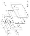
- FIG. 1 is a partially exploded perspective view of a computer housing.
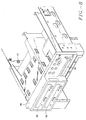
- FIG. 2 is a partial perspective view of a portion of the computer housing of FIG. 1.
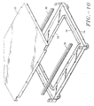
- FIG. 3 is an exploded perspective view of a midplane.
- FIG. 4 is a an enlarged perspective view of a mainboard mount of FIG. 3.
- FIG. 5 is a perspective view of a mainboard attaching to a midplane.
- FIG. 6 is a perspective view of a portion of a side cover assembly.
- FIG. 7 is a side view of the mainboard section of the computer housing of FIG. 1.
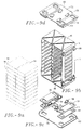
- FIG. 8 is a perspective view of a removable media storage unit of FIG. 1.
- FIG. 9a shows multiple memory storage devices.
- FIG. 9b shows a chassis assembly
- FIG 9c shows an isolation mount for the chassis assembly of FIG. 9b.
- FIG. 1 shows a rugged computer housing, i.e. a computer housing for protecting electronic components against shock and vibration, generally designated with the reference numeral 12.
- the housing 12 includes a base assembly 14, a chassis assembly 16, a midplane 18 and a side cover assembly 70 having a pair of side covers 20.
- the midplane 18 divides the computer housing 12 into a mainboard section 38 and a chassis section 40.
- the base assembly 14 includes a top face 22, a bottom face 24 and a plurality of casters 26.
- the casters 26 attach to the bottom face 24 to enable the computer housing 12 to roll.
- the top face 22 and the bottom face 24 mate to form a box beam 28.
- the box beam 28 includes reinforcing members 30 which define a portion of the box beam 28 and extend with the box beam 28 to provide rigidity to the base.
- the casters 26 attach to the bottom face 24, under the box beam 28.
- the box beam 28 reinforces the computer housing 12 to support the casters 26.
- the box beam 28 enables the computer hosing 12 to resist vibrations due to impact. Reinforcing the computer housing 12 with the box beam 28 also enables the base assembly 14 and the computer housing 12 to resist deformation, to protect the various electronic components within the computer housing 12.
- Excessive computer housing 12 weight may add stress to the connection between the casters 26 and the base and may increase the likelihood of deforming the base and the computer housing 12.
- the box beam minimizes computer housing 12 weight by providing structural support above the casters 26, where support is needed.
- the midplane 18 isolates the chassis section from the mainboard section. Components, such as disk drives, held in the chassis section 40 are thus isolated from the mainboard section 38. Isolation of components inhibits damage to mainboard section 38 components by chassis assembly 16 components due to vibration.
- the chassis section 40 includes a chassis assembly 16.
- the chassis assembly 16 is isolated as a unit from the remainder of the housing 12 to filter shock and vibration between the chassis assembly 16 and the remainder of the housing 12.
- the chassis assembly 16 includes multiple memory storage device units including a removable storage device module and multiple hard disk drives.
- the removable memory storage device module includes optical disk drives. It can be appreciated, however, that any of a number of memory storage devices may be used.
- Both side covers 20 have a generally "L" shaped cross-section. Each side cover 20 has a top portion. The top portion of each side cover 20 rests on the computer housing 12 to support weight including accessories, or even a seated person.
- FIG. 3 shows an embodiment of the midplane 18.
- the midplane 18 includes extensions 58 for mounting the midplane 18 into the base (FIG 1).
- the midplane 18 also includes several mainboard mounts 60 and a cross-rib 62.
- the extensions insert into the base assembly 14 (FIG 1) to hold the midplane 18.
- the midplane 18 adds rigidity to the housing 12 and isolates the chassis section 40 from the mainboard section 38.
- the cross rib 62 is stamped into the midplane 18 and includes contours which inhibit flexion of the midplane 18. Inhibiting flexion of the midplane 18 reduces flexion of the computer housing 12, the mainboard and the other electronic components. This makes the computer housing 12 more rugged in the face of shock and vibration. Increased ruggedness of the housing 12 makes the computer system and electronic components more reliable.
- FIG. 6 shows an exploded view of an embodiment of the side cover assembly, generally designated with the reference numeral 70.
- the side cover assembly 70 is a composite, being formed from a number of integrated elements.
- the composite side cover assembly 70 includes an outer cover 72 having a periphery 74, a gasket 76 attached within the periphery, an inner member 78 and a pad 80.
- the inner member 78 is fabricated from steel sheet metal to shield electromagnetic energy.
- the inner member also stiffens the side cover.
- the gasket 76 is fabricated in four pieces from sponge urethane rubber to enable the side cover assembly 70 to press fit against with the computer housing 12 side openings and thereby enable the composite side cover assembly structurally to reinforce the housing 12.
- the pad 80 attaches to the inner member 78.
- the pad 80 is fabricated from resilient foam and includes a contoured portion 82.
- the contoured portion 82 of the pad 80 is rectangular shape and coincides with the location of the processor unit 44 (FIG. 2) when the side cover assembly covers the computer housing 12. Accordingly, the contour of the pad presses against the processor unit to restrain the processor unit and to secure the side cover assembly against the housing 12. Restraining the processor unit 44 inhibits communication of vibration and shock to the processor. Securing the side cover assembly inhibits flexion of the housing 12.
- contoured portion 82 of the foam pad 80 is designed having a rectangular shape to press against the processor assembly 44, it can be appreciated that the contoured portion can be specifically designed to press against any of a variety of electronic components including memory chips, daughter boards and cards.
- FIG. 7 is a side view of a portion of the housing 12 where the side cover assembly 70 presses against the processor assembly 44 and a card 46.
- the outer cover 72 presses against the gasket 76, which presses against the inner member 78 which, in turn, presses against the foam pad 80, which presses against electronic components including the processor unit 44 and the card 46, which press into the mainboard 42, which presses against the midplane 18.
- the side cover assembly 70 compresses the foam pad 80 against the cards 46 to support the mainboard 42 and to enable the cards 46 and the mainboard 42 to internally support the computer housing 12. Holding the cards 46 with the pad 80 enables the mainboard 42, the side cover assembly 70 and the midplane 18 to function as a single unit.
- the side cover assembly, the mainboard 42 and the midplane 18 function as a composite structure.
- outer cover 72 The cooperation of the structure: outer cover 72, the gasket 76, the inner member, the foam pad, the electronic components including the processor unit 44 and the card 46, the mainboard 42, and the midplane 18, provides internal rigidity to the computer housing to inhibit flexion of the computer housing 12. This cooperation of structure also dampens vibrations while inhibiting movement of the various electronic components. This cooperation of structure also strengthens the side cover assembly 70 so that the computer housing 12 supports an increased amount of weight.
- FIG. 8 is a perspective view of the removable storage media unit 86.
- the unit 86 includes a pair of optical drives 88 and a floppy drive 90.
- the unit 86 mounts on resilient spacer mounts 92 to isolate the removable storage media unit from the remainder of the housing 12. Isolation of the removable storage media unit dampens vibrations to reduce the risk of damage to the optical drive 88 and floppy drive 90 during impact and vibrations.
- FIG. 9a shows multiple memory storage devices 94 which removeably insert into the chassis assembly 16.
- the memory storage devices 94 may be hard disk drives or virtually any other type of removable memory storage device.
- FIG. 9b, 9c and 9d show an exploded view of the disk chassis assembly 16.
- the chassis assembly 16 includes a top 96, a bottom 98 and a suspension mount.
- the suspension mount includes a pair of isolation mounts 100.
- the isolation mounts 100 attach to both the top 96 and to the bottom 98.
- FIG 9c and FIG 9d show top and bottom isolation mounts 100, respectively.
- the isolation mounts 100 each include a base plate 102, a pair of loose bar mounts 104, a capture bracket 106 and a plurality of high mass load snubbers 108.
- the base plate 102 supports the pair of loose bar mounts 104 in parallel.
- the capture bracket 106 holds the loose bar mounts 104 on the base plate and the snubbers 108 support the chassis independently of the loose bar mounts 104.
- the capture bracket 106 removeably attaches to the base plate 102 to secure the loose bar mounts 104 between the base plate 102 and the capture bracket 106.
- Each capture bracket has one side with tabs. The tabs insert into the base plate so that each capture bracket folds over the isolation mount.
- the snubbers 108 support the chassis assembly 96 independently of the loose bar mounts 104 and protect the disk chassis against severe impact.
- the chassis assembly 16 has lateral sides 112. Snubbers 108 attach to the lateral sides to protect the memory storage devices 94 against shock due to impact.
- the box beam 28 of the base assembly reinforces the base assembly so that the casters 26 may mount directly to the box beam 28.
- the box beam 28 may be modified in a number of ways which will operate to reinforce the base assembly 14 for the casters 26.
- the box beam functions not only to reinforce the base assembly 14, but also to diffuse forces encountered by the casters 26.
- Various box beam configurations will accomplish these goals.
- the box beam 28 may be modified or varied to have a trapezoidal, or circular cross-section, instead of the rectangular cross section.
- the housing can be particularly adapted in various shapes and configurations to house components other than those shown herein.
- the cooperation between elements which create and outer shell and inner support to the housing can manifest themselves in a wide variety of configurations.
Landscapes
- Engineering & Computer Science (AREA)
- Theoretical Computer Science (AREA)
- Computer Hardware Design (AREA)
- General Engineering & Computer Science (AREA)
- Power Engineering (AREA)
- Human Computer Interaction (AREA)
- Physics & Mathematics (AREA)
- General Physics & Mathematics (AREA)
- Casings For Electric Apparatus (AREA)
- Mounting Of Printed Circuit Boards And The Like (AREA)
Applications Claiming Priority (2)
| Application Number | Priority Date | Filing Date | Title |
|---|---|---|---|
| US892929 | 1997-07-15 | ||
| US08/892,929 US5867369A (en) | 1997-07-15 | 1997-07-15 | Rugged computer housing |
Publications (2)
| Publication Number | Publication Date |
|---|---|
| EP0892336A1 true EP0892336A1 (de) | 1999-01-20 |
| EP0892336B1 EP0892336B1 (de) | 2002-04-03 |
Family
ID=25400728
Family Applications (1)
| Application Number | Title | Priority Date | Filing Date |
|---|---|---|---|
| EP98305597A Expired - Lifetime EP0892336B1 (de) | 1997-07-15 | 1998-07-14 | Computergehäuse |
Country Status (4)
| Country | Link |
|---|---|
| US (1) | US5867369A (de) |
| EP (1) | EP0892336B1 (de) |
| JP (1) | JPH11110080A (de) |
| DE (1) | DE69804548T2 (de) |
Cited By (1)
| Publication number | Priority date | Publication date | Assignee | Title |
|---|---|---|---|---|
| EP2410398A1 (de) * | 2010-07-20 | 2012-01-25 | Liang-Ho Cheng | System aus Computern mit Tower-Gehäuse |
Families Citing this family (54)
| Publication number | Priority date | Publication date | Assignee | Title |
|---|---|---|---|---|
| NO986129L (no) * | 1998-12-23 | 2000-06-26 | Cit Alcatel | Beskyttet modulært hus for substrat |
| US6129429A (en) * | 1999-02-12 | 2000-10-10 | Compaq Computer Corporation | Rack serviceable computer chassis assembly |
| US6038126A (en) * | 1999-04-21 | 2000-03-14 | Shin Jiuh Corp. | Electrical power supply assembly |
| US6885550B1 (en) | 1999-08-26 | 2005-04-26 | Axxion Group Corporation | Screw less clip mounted computer drive |
| US6619766B1 (en) | 1999-10-12 | 2003-09-16 | Gateway, Inc. | Device mounting and retention assembly |
| US6293636B1 (en) | 1999-12-30 | 2001-09-25 | Gateway, Inc. | Device retention assembly |
| US6367748B1 (en) * | 2000-02-12 | 2002-04-09 | Solvisions Technologies Int'l | Apparatus for providing desktop mobility for desktop electronic devices |
| US6456489B1 (en) | 2000-05-25 | 2002-09-24 | Gateway, Inc. | Device retention apparatus |
| US6454250B1 (en) | 2000-10-17 | 2002-09-24 | Spx Corporation | Shock absorbing apparatus |
| US6795310B2 (en) * | 2000-12-28 | 2004-09-21 | Intel Corporation | Enhanced space utilization for enclosures enclosing heat management components |
| US6693371B2 (en) * | 2001-02-06 | 2004-02-17 | American Power Corporation | Integrated uninterruptible power supply enclosure |
| RU2329529C2 (ru) * | 2001-07-25 | 2008-07-20 | Интегрэф Хадвеа Текнолоджис Кампэни | Компьютерная консоль оператора и устройство воспроизведения изображений на экране (варианты) |
| USD481388S1 (en) | 2002-04-24 | 2003-10-28 | Kabushiki Kaisha Toshiba | Operation controller for electronic computers |
| USD481385S1 (en) | 2002-04-24 | 2003-10-28 | Kabushiki Kaisha Toshiba | Electronic computer |
| USD484508S1 (en) | 2002-11-27 | 2003-12-30 | International Business Machines Corporation | Server blade enclosure base |
| US7164581B2 (en) * | 2004-06-21 | 2007-01-16 | Computer Network Technology Corp. | Modular chassis divided along a midplane and cooling system therefor |
| US7663878B2 (en) * | 2006-03-23 | 2010-02-16 | Harris Kent Swan | Modular protective housing with peripherals for a handheld communications device |
| US20070241452A1 (en) * | 2006-04-12 | 2007-10-18 | Inventec Corporation | Electronic device with a movable mechanism |
| US7566104B2 (en) * | 2006-05-08 | 2009-07-28 | Lian Li Industrial Co., Ltd. | Bi-directional side emplacing computer casing |
| USD626955S1 (en) * | 2009-03-02 | 2010-11-09 | Verizon Patent And Licensing Inc. | Optical network terminal |
| CN102156508A (zh) * | 2010-02-11 | 2011-08-17 | 陈亮合 | 直立式电脑主机 |
| US8988895B2 (en) * | 2011-08-23 | 2015-03-24 | Tessera, Inc. | Interconnection elements with encased interconnects |
| USD673959S1 (en) * | 2011-10-13 | 2013-01-08 | Hewlett-Packard Development Company, L.P. | Cover plate for a computing device |
| USD673160S1 (en) * | 2011-10-13 | 2012-12-25 | Hewlett-Packard Development Company, L.P. | Cover plate for a computing device |
| USD673161S1 (en) * | 2011-10-13 | 2012-12-25 | Hewlett-Packard Development Company, L.P. | Perforation pattern for a cover plate for a computing device |
| USD672354S1 (en) * | 2011-10-13 | 2012-12-11 | Hewlett-Packard Development Company, L.P. | Cover plate for a computing device |
| WO2013119243A1 (en) | 2012-02-09 | 2013-08-15 | Hewlett-Packard Development Company, L.P. | Heat dissipating system |
| EP2826347B1 (de) | 2012-03-12 | 2017-10-25 | Hewlett-Packard Enterprise Development LP | Kühlung einer flüssigkeitstemperaturregelung |
| USD698074S1 (en) | 2012-04-17 | 2014-01-21 | Ip Holdings, Llc | External ballast frame |
| EP2901828A4 (de) | 2012-09-28 | 2016-06-01 | Hewlett Packard Development Co | Kühlanordnung |
| EP2915417B1 (de) | 2012-10-31 | 2017-11-29 | Hewlett-Packard Enterprise Development LP | Modulares regalsystem |
| USD707224S1 (en) * | 2012-12-21 | 2014-06-17 | Zalman Tech Co., Ltd. | Computer case |
| USD706273S1 (en) * | 2013-01-04 | 2014-06-03 | Hewlett-Packard Development Company, L.P. | Bezel for a computing device |
| USD705784S1 (en) * | 2013-01-04 | 2014-05-27 | Hewlett-Packard Development Company, L.P. | Bezel for a computing device |
| USD707225S1 (en) * | 2013-01-22 | 2014-06-17 | Zalman Tech Co., Ltd. | Computer case |
| FR3001603B1 (fr) * | 2013-01-29 | 2015-03-20 | Airbus Operations Sas | Carte electronique pour equipement avionique comprenant des moyens amortisseurs de vibrations entre son cadre de renfort et ses moyens de maintien |
| WO2014120182A1 (en) | 2013-01-31 | 2014-08-07 | Hewlett-Packard Development Company, L.P. | Liquid cooling |
| ITRM20130540A1 (it) * | 2013-10-04 | 2015-04-05 | Ecm S P A | Posto periferico di controllo di enti di piazzale ferroviario e metodo di installazione di detto posto periferico |
| USD740282S1 (en) * | 2013-10-22 | 2015-10-06 | Western Digital Technologies, Inc. | Storage device |
| USD757344S1 (en) * | 2014-08-26 | 2016-05-24 | Ip Holdings, Llc | Ballast housing |
| USD761481S1 (en) * | 2014-08-26 | 2016-07-12 | Ip Holdings, Llc | Ballast housing |
| USD760222S1 (en) | 2014-10-29 | 2016-06-28 | Western Digital Technologies, Inc. | Storage device |
| USD780691S1 (en) | 2015-05-20 | 2017-03-07 | Ip Holdings, Llc | Remote ballast |
| CN104951023A (zh) * | 2015-07-15 | 2015-09-30 | 王学香 | 一种加固计算机 |
| US20190094911A1 (en) * | 2017-09-25 | 2019-03-28 | The United State Of America As Represented By The Secretary Of The Navy | System and Method for Ruggedized Remote Communication |
| USD855238S1 (en) | 2017-10-27 | 2019-07-30 | Hgci, Inc. | Ballast |
| USD871654S1 (en) | 2017-10-30 | 2019-12-31 | Hgci, Inc. | Light fixture |
| USD895607S1 (en) | 2019-05-31 | 2020-09-08 | Apple Inc. | Electronic device |
| USD942441S1 (en) * | 2019-06-01 | 2022-02-01 | Apple Inc. | Electronic device |
| KR102565678B1 (ko) * | 2020-10-26 | 2023-08-14 | (주)케이티엔에프 | 현장 온도를 감내하기 위한 엣지컴퓨팅시스템 |
| KR102565749B1 (ko) * | 2020-10-26 | 2023-08-16 | (주)케이티엔에프 | 러기드 환경을 위한 엣지컴퓨팅시스템 |
| WO2022104416A1 (en) * | 2020-11-17 | 2022-05-27 | Tritium Holdings Pty Ltd | A modular electronics assembly |
| CN112739094B (zh) * | 2020-12-22 | 2022-03-22 | 安徽飞凯电子技术有限公司 | 一种服务器用智能降噪机柜 |
| JP7711487B2 (ja) * | 2021-08-23 | 2025-07-23 | 富士フイルムビジネスイノベーション株式会社 | キャスタ保護構造及びこれを用いた筐体構造、物品 |
Citations (4)
| Publication number | Priority date | Publication date | Assignee | Title |
|---|---|---|---|---|
| EP0328260A2 (de) * | 1988-02-12 | 1989-08-16 | Mdb Systems, Inc. | Stossisoliertes tragbares Massenspeichergerät |
| WO1993001599A1 (de) * | 1991-07-13 | 1993-01-21 | Tappert Karl Heinz | Lagerung für ein festplattenlaufwerk oder dgl. |
| EP0524734A1 (de) * | 1991-06-27 | 1993-01-27 | Compaq Computer Corporation | Sicherheitsverschluss für doppelwändiges Datenverarbeitungsgerät |
| US5590023A (en) * | 1995-07-26 | 1996-12-31 | Dell Usa Lp | Computer apparatus for suspension of computer expansion cards |
Family Cites Families (7)
| Publication number | Priority date | Publication date | Assignee | Title |
|---|---|---|---|---|
| US4728160A (en) * | 1986-10-22 | 1988-03-01 | Digital Equipment Corporation | Cabinet for a computer assembly |
| US5040161A (en) * | 1989-04-27 | 1991-08-13 | Hewlett-Packard Company | Sheet metal housing with precision mounting references |
| US5031070A (en) * | 1990-06-05 | 1991-07-09 | Kai Hsu | Structure of computer housing |
| US5271152A (en) * | 1990-12-07 | 1993-12-21 | Compuadd Corporation | Process for making a computer tower chassis using modules |
| US6640235B1 (en) * | 1992-08-20 | 2003-10-28 | Intel Corporation | Expandable mass disk drive storage system |
| US5349132A (en) * | 1993-02-08 | 1994-09-20 | Apple Computer, Inc. | Methods and apparatus for modular computer construction |
| US5680295A (en) * | 1995-11-13 | 1997-10-21 | Ast Research, Inc. | Ventilated backplane for mounting disk drives in computer systems |
-
1997
- 1997-07-15 US US08/892,929 patent/US5867369A/en not_active Expired - Lifetime
-
1998
- 1998-07-14 DE DE69804548T patent/DE69804548T2/de not_active Expired - Fee Related
- 1998-07-14 EP EP98305597A patent/EP0892336B1/de not_active Expired - Lifetime
- 1998-07-15 JP JP10200220A patent/JPH11110080A/ja active Pending
Patent Citations (4)
| Publication number | Priority date | Publication date | Assignee | Title |
|---|---|---|---|---|
| EP0328260A2 (de) * | 1988-02-12 | 1989-08-16 | Mdb Systems, Inc. | Stossisoliertes tragbares Massenspeichergerät |
| EP0524734A1 (de) * | 1991-06-27 | 1993-01-27 | Compaq Computer Corporation | Sicherheitsverschluss für doppelwändiges Datenverarbeitungsgerät |
| WO1993001599A1 (de) * | 1991-07-13 | 1993-01-21 | Tappert Karl Heinz | Lagerung für ein festplattenlaufwerk oder dgl. |
| US5590023A (en) * | 1995-07-26 | 1996-12-31 | Dell Usa Lp | Computer apparatus for suspension of computer expansion cards |
Cited By (1)
| Publication number | Priority date | Publication date | Assignee | Title |
|---|---|---|---|---|
| EP2410398A1 (de) * | 2010-07-20 | 2012-01-25 | Liang-Ho Cheng | System aus Computern mit Tower-Gehäuse |
Also Published As
| Publication number | Publication date |
|---|---|
| EP0892336B1 (de) | 2002-04-03 |
| DE69804548D1 (de) | 2002-05-08 |
| US5867369A (en) | 1999-02-02 |
| DE69804548T2 (de) | 2002-10-31 |
| JPH11110080A (ja) | 1999-04-23 |
Similar Documents
| Publication | Publication Date | Title |
|---|---|---|
| EP0892336B1 (de) | Computergehäuse | |
| US6498722B1 (en) | Disk drive isolation mount | |
| US5209356A (en) | Acoustic rack | |
| US6049449A (en) | Computer with modular removable card cage | |
| US5004207A (en) | Shock mounting structure and magnetic disk apparatus | |
| US7227761B2 (en) | Apparatus for resiliently mounting a circuit board within a device housing | |
| US6094342A (en) | Disk drive jacket | |
| US7420798B2 (en) | Portable microcomputer and display unit | |
| US6320760B1 (en) | Multiple PCI card support | |
| US6606242B2 (en) | Universal adapter bracket for mounting electronic devices | |
| CN211604019U (zh) | 一种便于拆装的塑料机箱外壳 | |
| KR100267163B1 (ko) | 래크에 설치가능한 섀시 인클로우져 | |
| US6652314B2 (en) | Components for a computer sub-assembly | |
| US20080013273A1 (en) | Computer chassis having a tuning gasket | |
| US6233147B1 (en) | Apparatus for securing a component in a computer chassis | |
| JPH08223942A (ja) | インバータの寿命部品の着脱装置 | |
| US5221811A (en) | Shock mounting housing apparatus | |
| JPH06236669A (ja) | 記憶装置の衝撃緩衝部材 | |
| JP4369914B2 (ja) | コンピュータシステムへのコンポーネントの取付け装置 | |
| EP3611436B1 (de) | Ausseneinheit einer klimaanlage | |
| US5661636A (en) | IC card with on-board hard disk and circuit board with on-board hard disk including a cover with a bulging portion accommodating the hard disk | |
| US5261648A (en) | Computer isolating device | |
| CN214196593U (zh) | 一种压缩机防撞结构及电器设备 | |
| JPH03110329A (ja) | 空気調和機の圧縮機支持装置 | |
| CN224081998U (zh) | 一种减震型服务器机箱 |
Legal Events
| Date | Code | Title | Description |
|---|---|---|---|
| PUAI | Public reference made under article 153(3) epc to a published international application that has entered the european phase |
Free format text: ORIGINAL CODE: 0009012 |
|
| AK | Designated contracting states |
Kind code of ref document: A1 Designated state(s): DE FR GB IT NL SE |
|
| AX | Request for extension of the european patent |
Free format text: AL;LT;LV;MK;RO;SI |
|
| 17P | Request for examination filed |
Effective date: 19990629 |
|
| AKX | Designation fees paid |
Free format text: DE FR GB IT NL SE |
|
| 17Q | First examination report despatched |
Effective date: 19990831 |
|
| GRAG | Despatch of communication of intention to grant |
Free format text: ORIGINAL CODE: EPIDOS AGRA |
|
| GRAG | Despatch of communication of intention to grant |
Free format text: ORIGINAL CODE: EPIDOS AGRA |
|
| GRAG | Despatch of communication of intention to grant |
Free format text: ORIGINAL CODE: EPIDOS AGRA |
|
| GRAH | Despatch of communication of intention to grant a patent |
Free format text: ORIGINAL CODE: EPIDOS IGRA |
|
| GRAH | Despatch of communication of intention to grant a patent |
Free format text: ORIGINAL CODE: EPIDOS IGRA |
|
| REG | Reference to a national code |
Ref country code: GB Ref legal event code: IF02 |
|
| GRAA | (expected) grant |
Free format text: ORIGINAL CODE: 0009210 |
|
| AK | Designated contracting states |
Kind code of ref document: B1 Designated state(s): DE FR GB IT NL SE |
|
| REF | Corresponds to: |
Ref document number: 69804548 Country of ref document: DE Date of ref document: 20020508 |
|
| PGFP | Annual fee paid to national office [announced via postgrant information from national office to epo] |
Ref country code: FR Payment date: 20020710 Year of fee payment: 5 |
|
| PGFP | Annual fee paid to national office [announced via postgrant information from national office to epo] |
Ref country code: GB Payment date: 20020712 Year of fee payment: 5 |
|
| PGFP | Annual fee paid to national office [announced via postgrant information from national office to epo] |
Ref country code: SE Payment date: 20020717 Year of fee payment: 5 |
|
| PGFP | Annual fee paid to national office [announced via postgrant information from national office to epo] |
Ref country code: NL Payment date: 20020731 Year of fee payment: 5 |
|
| PGFP | Annual fee paid to national office [announced via postgrant information from national office to epo] |
Ref country code: DE Payment date: 20020807 Year of fee payment: 5 |
|
| ET | Fr: translation filed | ||
| PLBE | No opposition filed within time limit |
Free format text: ORIGINAL CODE: 0009261 |
|
| STAA | Information on the status of an ep patent application or granted ep patent |
Free format text: STATUS: NO OPPOSITION FILED WITHIN TIME LIMIT |
|
| 26N | No opposition filed |
Effective date: 20030106 |
|
| PG25 | Lapsed in a contracting state [announced via postgrant information from national office to epo] |
Ref country code: GB Free format text: LAPSE BECAUSE OF NON-PAYMENT OF DUE FEES Effective date: 20030714 |
|
| PG25 | Lapsed in a contracting state [announced via postgrant information from national office to epo] |
Ref country code: SE Free format text: LAPSE BECAUSE OF NON-PAYMENT OF DUE FEES Effective date: 20030715 |
|
| PG25 | Lapsed in a contracting state [announced via postgrant information from national office to epo] |
Ref country code: NL Free format text: LAPSE BECAUSE OF NON-PAYMENT OF DUE FEES Effective date: 20040201 |
|
| PG25 | Lapsed in a contracting state [announced via postgrant information from national office to epo] |
Ref country code: DE Free format text: LAPSE BECAUSE OF NON-PAYMENT OF DUE FEES Effective date: 20040203 |
|
| EUG | Se: european patent has lapsed | ||
| GBPC | Gb: european patent ceased through non-payment of renewal fee |
Effective date: 20030714 |
|
| PG25 | Lapsed in a contracting state [announced via postgrant information from national office to epo] |
Ref country code: FR Free format text: LAPSE BECAUSE OF NON-PAYMENT OF DUE FEES Effective date: 20040331 |
|
| NLV4 | Nl: lapsed or anulled due to non-payment of the annual fee |
Effective date: 20040201 |
|
| REG | Reference to a national code |
Ref country code: FR Ref legal event code: ST |
|
| PG25 | Lapsed in a contracting state [announced via postgrant information from national office to epo] |
Ref country code: IT Free format text: LAPSE BECAUSE OF NON-PAYMENT OF DUE FEES Effective date: 20050714 |