EP0328635B1 - Structure de reglage des surfaces d'un reflecteur - Google Patents
Structure de reglage des surfaces d'un reflecteur Download PDFInfo
- Publication number
- EP0328635B1 EP0328635B1 EP88908810A EP88908810A EP0328635B1 EP 0328635 B1 EP0328635 B1 EP 0328635B1 EP 88908810 A EP88908810 A EP 88908810A EP 88908810 A EP88908810 A EP 88908810A EP 0328635 B1 EP0328635 B1 EP 0328635B1
- Authority
- EP
- European Patent Office
- Prior art keywords
- antenna
- truss
- shells
- shell
- shell supporting
- Prior art date
- Legal status (The legal status is an assumption and is not a legal conclusion. Google has not performed a legal analysis and makes no representation as to the accuracy of the status listed.)
- Expired - Lifetime
Links
Images

Classifications
-
- H—ELECTRICITY
- H01—ELECTRIC ELEMENTS
- H01Q—ANTENNAS, i.e. RADIO AERIALS
- H01Q15/00—Devices for reflection, refraction, diffraction or polarisation of waves radiated from an antenna, e.g. quasi-optical devices
- H01Q15/14—Reflecting surfaces; Equivalent structures
- H01Q15/16—Reflecting surfaces; Equivalent structures curved in two dimensions [2D], e.g. paraboloidal
-
- H—ELECTRICITY
- H01—ELECTRIC ELEMENTS
- H01Q—ANTENNAS, i.e. RADIO AERIALS
- H01Q15/00—Devices for reflection, refraction, diffraction or polarisation of waves radiated from an antenna, e.g. quasi-optical devices
- H01Q15/14—Reflecting surfaces; Equivalent structures
- H01Q15/147—Reflecting surfaces; Equivalent structures provided with means for controlling or monitoring the shape of the reflecting surface
Definitions
- This invention relates to an antenna comprising:
- the invention regards a structure which permits adjustment of the reflector surface of a reflector as the last manufacturing step and minimizes distortion of the reflector surface upon temperature changes and temperature differential.
- the adjustment structure is particularly useful for the adjustment of two surfaces which lie within the curvature of each other so they are nested together.
- Reflector shells are used to reflect and focus radio-frequency energy radiating from a feed.
- the shape of the reflector shell In order to correctly focus the energy, the shape of the reflector shell must initially be close to the theoretical shape, and it must maintain its contour over changes in temperature and changes in temperature differential across the reflector surface.
- US 3,438,045, US 3,383,692 and US 4,650,361 disclose dual-reflector antennae with reflector adjustment capability.
- these prior art antennae are based on main reflector/subreflector combinations wherein the subreflector is located at the focal point of the main reflector and thus receives/transmits electromagnetic waves reflected from/to the main reflector.
- adjustment of the subreflector as a whole is critical, as the subreflector must precisely be positioned at the focal point of the main reflector, in order to ensure proper operation.
- the latter two documents (US 3,383,692 and US 4,650,361) also provide means for adjustment of the contour of the segments of the main reflector.
- the present invention provides forward and rear antenna shells which are nested such that both of their reflective surfaces are forward reflective surfaces. That is, they provide double use and do not act in combination.
- An antenna according to the present invention is thus characterized by the following features:
- a reflector shell adjustment structure wherein a support structure carries at least one reflector shell thereon, with adjustment structure attaching the reflector shell to the support structure so that, as a last step in the manufacturing process, the reflector shell is supported at optimum configuration and is securely attached to the support structure at that configuration.
- Two nested reflector shells can be mounted and adjusted with respect to the support structure.
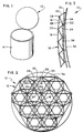
- FIG. 1 is an isometric view of a device upon which the structure of this invention is useful.
- FIG. 2 is a plan view of a support structure for the reflector shells.
- FIG. 3 is an offset section through the reflector shell and support structure assembly.
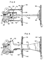
- FIG. 4 is an enlarged center-line section through one of the adjustment structure which support the reflector shells from the support structure.
- FIG. 5 is a side view of the structure shown in FIG. 4, with center-line sections and broken sections.
- FIG. 6 is a side-elevational view, similar in orientation to FIG. 4, showing the tooling used in the adjustment of the back reflector shell with respect to the support structure..
- FIG. 7 is a view similar to FIG. 5, on reduced scale, showing the tooling used in adjusting the forward reflector shell.
- the support structure 12 is a dynamically rigid truss structure.
- the truss structure is mounted upon base 14, which carries the radio-frequency transmitter and/or receiver.
- the base may be any conventional ground structure or may be a satellite in space.
- the truss structure provides the necessary strength and rigidity to withstand the loads encountered during satellite launch and provides the structural and thermal stability needed for temperature changes and temperature differentials found in orbit and in other locations.
- the truss support structure may be made very light by the employment of tubular truss members of continuous fiber composite material such as graphite in an epoxy matrix. When weight is not critical, the truss may be made of other materials.
- truss rods 16 and 18 are joined at node 20.
- these truss rods are seen to be at the back of the support structure.
- truss rods which reach forward in the truss to attach forward nodes.
- Forward node 22 is seen in FIGS. 2 and 3, with truss rod 24 joining nodes 20 and 22, truss rod 26 joining nodes 22 and 28, truss rod 30 joining nodes 28 and 32, and truss rod 34 joining nodes 22 and 32 at the forward part of the truss.
- the nodes 22, 32 and the other nodes along the forward face of the truss provide the interconnection point at which the adjustment structures attach to the truss to support reflector shells 36 and 38.
- the shells are preferably made with a honeycomb sandwich construction.
- the forward faces 40 and 42 in FIGS. 4 and 5 are the reflector surfaces which have the critical surface shape which is to be initially adjusted and then maintained, in accordance with the structure of this invention.
- the two reflectors may be fed with radio waves with different polarizations, and the front shell 38 and its reflective surface 42 are constructed so that they are substantially transparent to the energy reflected off of surface 40.
- the two reflector shells can be nested to provide double use for the same truss and conserve space.
- the truss rods terminate in rod ends which are pinned at the nodal fittings.
- Forward node 22 is illustrated in more detail in FIGS. 4, 5, 6 and 7 and show the lugs at which the truss rods are pinned.
- the shells of the double surface reflector are independently attached to the dynamically rigid truss structure by means of studs at each of the forward nodes.
- Each of the forward nodes has a body, with the body of node 22 generally indicated at 44, as seen in FIGS. 4 and 5.
- the body has a central bore 46 which is threaded for temporary receipt of an adjustment tool, as described hereinafter.
- the bore defines the central axis of the body.
- the body has lugs thereon by which the truss rods are pinned to the body.
- the body has an exterior right circular cylindrical engagement surface 48 and an interior right circular cylindrical engagement surface 50. Both of these surfaces are coaxial with the central axis of the body, as defined by bore 46.
- Rear shell stud 52 has a forward outwardly extending flange 54 which is bonded to the back surface of the rear reflector shell 36.
- the interior surface of the rear shell stud 52 is in the form of a right circular cylinder sized to be a slip fit onto the engagement surface 48, as shown in FIG. 4.
- the interface 56 between the stud interior surface and engagement surface needs only to be adhesive bonded to secure body 44 to rear shell 36. However, before adhesive is placed in this interface, the position of the shell may be adjusted with respect to the truss. To accomplish this adjustment, the rear shell adjustment tool 58 is temporarily installed for the adjustment process, see FIG. 6. A similar tool is installed at each of the forward nodes so that the entire shell configuration can be adjusted at one time.
- Rear shell adjusting tool 58 has a forward threaded boss 60 on yoke 62.
- Micrometer adjustor 64 is threaded into the rear end of the yoke and has a forward extending rod 66.
- Rod 66 can be adjusted forward and back along the axis of bore 46 in small increments.
- Swivel coupling 68 couples rod 66 to adjusting rod 70, which extends down through the open center of yoke 62.
- Adjusting rod 70 carries ball 72 on its forward end, which is mounted in a corresponding socket in bridge 74. As is best seen in FIG.
- a portion of the cylindrical section of the rear shell stud 52 is cut away between the interface 56 and flange 54 to provide a view to the interior of the tube and to define two legs 76 and 78.
- Bridge 74 is mounted between these legs and is secured thereto by means of removable machine screws extending through the legs and into the bridge, as shown in FIG. 6.
- the rear reflector shell 36 is adjusted to an optimized position.
- the truss is independent of other structure and thus serves as a secure stable reference for carrying the rear reflector shell and holding it in the desired optimized position.
- the shell 36 is originally manufactured to approximate the desired configuration, usually a parabola for transmission of a spot beam.
- the shell will have inherent distortion due to manufacturing and material limitations.
- the post-manufacturing adjustment when the shell is mounted on its supporting truss reduces this distortion to improve the shell's performance.
- the amount of adjustment necessary to optimize performance may be determined by adjusting the shell during electrical performance tests. Adjustment at each of the studs brings the reflective surface of the rear shell into the optimized configuration. When the optimal configuration is reached, adhesive is fed into the interface 56 of each stud to hold the rear shell in place with respect to the truss.
- forward shell 38 is located in place and studs are secured thereto at each of the forward nodes.
- forward stud 80 is a flat stud with a rectangular cross section of fairly high aspect ratio to give strength within the plane of the stud and permit flexibility in the direction perpendicular to the plane of the stud.
- the forward portion of the stud carries flange 82, which is bonded to the back of forward shell 38.
- Forward stud 80 extends back through an opening 84 into the space within interior engagement surface 50.
- the rearward end of forward stud 80 carries plunger 86 thereon, which has a slip fit within interior engagement surface 50.
- Plunger 86 has threaded adjustor attachment hole 88 in line with and facing bore 46.
- Forward shell adjustment tool 90 seen in FIG. 7, has the same yoke 62 and micrometer adjustor 64.
- the forward end of the yoke is threaded into bore 46.
- the rod 66 of the micrometer adjustor carries swivel coupling 92 by which the micrometer rod 66 is coupled to adjusting rod 94.
- the adjusting rod 94 is, in turn, threaded into the adjustment hole 88 in plunger 86. If necessary, couplings 68 and 92 can incorporate swivels to permit relative rotation.
- the position of stud 80 can be adjusted with respect to node 22.
- a similar adjustment tool is provided at each of the nodes, and the forward shell 38 is adjusted to its most desirable configuration.
- adhesive is fed into the interface space between surface 50 and plunger 86, to permanently hold the forward shell in position with respect to node 22, and thus the balance of the truss. Thereupon, the adjustment tools are removed and the manufacturing for the dish structure is complete.
- the stud structure is arranged for minimum transfer of distortion between each of the shells and the truss structure. Such distortion occurs due to temperature changes and temperature differences across the structure.
- Each of the dishes is a surface of revolution, probably parabolic or close to parabolic, as previously discussed.
- the legs 76 and 78 of stud 52 and the flat blade of forward stud 80 are each arranged so that the stiff planes thereof are normal to the radial direction of the normal axis at the center of the reflector surface.
Landscapes
- Physics & Mathematics (AREA)
- Electromagnetism (AREA)
- Aerials With Secondary Devices (AREA)
- Variable-Direction Aerials And Aerial Arrays (AREA)
Abstract
Claims (12)
- Antenne (10) comprenant:- des coques d'antenne avant et arrière (38, 36), lesdites coques d'antenne (38, 36) ayant respectivement des surfaces réfléchissantes (40, 42) ;- un treillis (12) de support de coques disposé à l'arrière d'au moins une partie desdites coques d'antenne (38, 36) ;- un ensemble de montants (52) de support de coque arrière partant de ladite coque arrière vers ledit treillis (12) pour supporter ladite coque arrière (36) sur ledit treillis (12) ;caractérisée en ce que- lesdites coques d'antenne avant et arrière (38, 36) sont imbriquées de telle façon que lesdites deux surfaces réfléchissantes (40, 42) sont des surfaces réfléchissantes vers l'avant;- ladite coque d'antenne avant (38) est sensiblement transparente à l'énergie réfléchie sur la surface (40) de ladite coque d'antenne arrière (36); et caractérisée en outre par:- un ensemble de montants (80) de support de coque avant s'étendant entre ladite coque d'antenne avant (38) et ledit treillis (12) à travers une ouverture (84) pratiquée dans ladite coque d'antenne arrière (36),- lesdits montants (80) de support de coque avant étant indépendants desdits montants (52) de support de coque d'antenne arrière, de sorte que lesdites coques d'antenne avant et arrière (38, 36) sont supportées indépendamment l'une de l'autre sur ledit treillis (12) par lesdits montants (52, 80).
- Antenne (10) selon la revendication 1, caractérisée en ce que ledit treillis (12) comporte un ensemble de tirants (16, 18, 24, 26, 30, 34) et un ensemble de noeuds (20, 22, 28, 32) où lesdits tirants (16, 18, 24, 26, 30, 34) se rejoignent, ledit treillis (12) ayant des noeuds (22, 32) de support de coques vers lesdites coques d'antenne (38, 36) et ayant d'autres noeuds (20, 28) éloignés desdites coques d'antenne (38, 36), lesdits montants (52, 80) de support des coques avant et arrière étant reliés audit treillis (12) par lesdits noeuds de support (22, 32).
- Antenne (10) selon la revendication 1 ou 2, caractérisée en ce que lesdits montants (52, 80) de support de coques avant et arrière sont réglables par rapport audit treillis (12) de façon que le contour de la surface réfléchissante desdites coques d'antenne avant et arrière (38, 36) puisse être réglé pendant la fixation de chacune desdites coques d'antenne (38, 36), par rapport audit treillis (12).
- Antenne (10) selon la revendication 2 ou 3, caractérisée en ce que chacun desdits montants (52, 80) de support de coques avant et arrière est réglable indépendamment par rapport audit noeud de support (22, 32) de façon que chacune desdites coques d'antenne (38, 36) puisse être réglée indépendamment par rapport à chacun desdits noeuds de support (22, 32) lors de l'assemblage de chacune desdites coques d'antenne (38, 36), par rapport audit treillis (12), de façon à optimiser le contour de ladite surface réfléchissante desdites coques d'antenne (38, 36).
- Antenne (10) selon la revendication 3 ou 4, caractérisée en ce que lesdits montants (52, 80) de support de coques avant et arrière s'engagent dans lesdits noeuds de support (22, 32) sur des surfaces coulissantes (48, 50) au moyen desquelles lesdits montants (52, 80) de support de coques avant et arrière coulissent pour se rapprocher et s'éloigner desdits noeuds de support (22, 32) afin de régler la position desdites coques avant et arrière (38, 36) par rapport auxdits noeuds de support (22, 32) et audit treillis (12).
- Antenne (10) selon la revendication 5, caractérisée en ce que lesdits montants (52, 80) de support de coques avant et arrière peuvent être fixés auxdites surfaces coulissantes (48, 50).
- Antenne (10) selon la revendication 6, caractérisée par un adhésif sur lesdites surfaces coulissantes (48, 50) pour fixer lesdites coques d'antenne (38, 36) par rapport audit treillis (12).
- Antenne (10) selon l'une quelconque des revendications précédentes, caractérisée en ce que chacun desdits montants (52, 80) de support de coques avant et arrière est sensiblement plan, lesdits montants plans ayant un axe perpendiculaire aux centres desdites surfaces réfléchissantes (40, 42) et étant plus épais dans une direction perpendiculaire au rayon partant d'un axe de révolution desdites coques d'antenne avant et arrière (38, 36) que dans une direction parallèle à ce rayon, de sorte que chacune desdites surfaces réfléchissantes (40, 42) puisse se déformer plus facilement dans une direction radiale par rapport audit axe que dans une direction perpendiculaire à chacun desdits rayons.
- Antenne (10) selon la revendication 6, caractérisée en ce que lesdites surfaces coulissantes (48, 50) s'étendent globalement vers lesdites coques d'antenne avant et arrière (38, 36).
- Antenne (10) selon la revendication 9, caractérisée en ce que lesdits deux montants (52, 80) de support de coques avant et arrière sont sensiblement plans et sont disposés sensiblement parallèlement l'un à l'autre.
- Antenne (10) selon la revendication 10, caractérisée en ce que ladite surface coulissante (48) est un cylindre de révolution et en ce que ledit montant (52) de support de coque arrière est un tube cylindrique évidé pour former des première et deuxième branches (76, 78), lesdites première et deuxième branches (76, 78) étant sensiblement parallèles audit montant (80) de support de coque avant.
- Antenne (10) selon la revendication 11, caractérisée en ce que ledit montant (80) de support de coque avant présente une section transversale rectangulaire, lesdites coques d'antenne avant et arrière (38, 36) étant des surfaces de révolution, ayant un axe de révolution et en ce que lesdits montants (52, 80) de support de coques avant et arrière sont plus épais dans une direction perpendiculaire à un rayon partant dudit axe de révolution que dans une direction parallèle à ce rayon.
Applications Claiming Priority (3)
| Application Number | Priority Date | Filing Date | Title |
|---|---|---|---|
| US83489 | 1987-08-10 | ||
| US07/083,489 US4845510A (en) | 1987-08-10 | 1987-08-10 | Reflector surface adjustment structure |
| PCT/US1988/002190 WO1989001708A1 (fr) | 1987-08-10 | 1988-07-01 | Structure de reglage des surfaces d'un reflecteur |
Publications (2)
| Publication Number | Publication Date |
|---|---|
| EP0328635A1 EP0328635A1 (fr) | 1989-08-23 |
| EP0328635B1 true EP0328635B1 (fr) | 1994-11-30 |
Family
ID=22178682
Family Applications (1)
| Application Number | Title | Priority Date | Filing Date |
|---|---|---|---|
| EP88908810A Expired - Lifetime EP0328635B1 (fr) | 1987-08-10 | 1988-07-01 | Structure de reglage des surfaces d'un reflecteur |
Country Status (6)
| Country | Link |
|---|---|
| US (1) | US4845510A (fr) |
| EP (1) | EP0328635B1 (fr) |
| JP (1) | JPH0795653B2 (fr) |
| CA (1) | CA1307044C (fr) |
| DE (1) | DE3852293T2 (fr) |
| WO (1) | WO1989001708A1 (fr) |
Families Citing this family (10)
| Publication number | Priority date | Publication date | Assignee | Title |
|---|---|---|---|---|
| FR2678111B1 (fr) * | 1991-06-19 | 1993-10-22 | Aerospatiale Ste Nationale Indle | Reflecteur d'antenne reconfigurable en service. |
| CA2137678A1 (fr) * | 1992-06-23 | 1994-01-06 | Barry Frederick Parsons | Methode et dispositif pour la formation de reseaux de nervures |
| JP3039607B2 (ja) * | 1994-12-20 | 2000-05-08 | 三菱電機株式会社 | 反射鏡支持機構 |
| US6208317B1 (en) * | 2000-02-15 | 2001-03-27 | Hughes Electronics Corporation | Hub mounted bending beam for shape adjustment of springback reflectors |
| US7173575B2 (en) * | 2005-01-26 | 2007-02-06 | Andrew Corporation | Reflector antenna support structure |
| US7301508B1 (en) * | 2006-10-10 | 2007-11-27 | The United States Of America As Represented By The Secretary Of The Air Force | Optimization of near field antenna characteristics by aperture modulation |
| CN102099637B (zh) | 2008-06-06 | 2016-10-19 | 日出Csp股份有限公司 | 太阳能热收集器的改进 |
| US9337544B2 (en) | 2013-01-07 | 2016-05-10 | Lockheed Martin Corporation | Configurable backing structure for a reflector antenna and corrective synthesis for mechanical adjustment thereof |
| US10727605B2 (en) * | 2018-09-05 | 2020-07-28 | Eagle Technology, Llc | High operational frequency fixed mesh antenna reflector |
| CN110375705B (zh) * | 2019-08-20 | 2020-07-21 | 大连理工大学 | 天线反射器及其型面变形测量方法和对比测量方法 |
Family Cites Families (13)
| Publication number | Priority date | Publication date | Assignee | Title |
|---|---|---|---|---|
| US348045A (en) * | 1886-08-24 | Electrical annunciator | ||
| DE1117670B (de) * | 1960-08-24 | 1961-11-23 | Deutsche Elektronik Gmbh | In einer senkrechten Ebene kippbare Fernsehantenne |
| US3105969A (en) * | 1960-12-23 | 1963-10-01 | North American Aviation Inc | Antenna reflector construction |
| US3383692A (en) * | 1965-01-07 | 1968-05-14 | Whittaker Corp | Main dish with adjustable subreflector |
| US3401390A (en) * | 1965-05-28 | 1968-09-10 | Whittaker Corp | Adjustable positioning and support device for antenna reflector panels |
| US3438045A (en) * | 1966-02-23 | 1969-04-08 | Whittaker Corp | Dish reflector with adjustable subreflector |
| US3898667A (en) * | 1974-02-06 | 1975-08-05 | Rca Corp | Compact frequency reuse antenna |
| DE3406288A1 (de) * | 1983-12-24 | 1985-10-17 | Dornier System Gmbh, 7990 Friedrichshafen | Knoten fuer fachwerkstrukturen aus faserverbundwerkstoff |
| JPS60210004A (ja) * | 1983-12-24 | 1985-10-22 | ドルニエ、ジステム、ゲゼルシヤフト、ミツト、ベシユレンクテル、ハフツング | 繊維複合材料から成る骨組支持構造物の節継手 |
| SU1252844A1 (ru) * | 1985-03-18 | 1986-08-23 | Предприятие П/Я А-1836 | Способ измерени поверхности антенны |
| JPS6244511U (fr) * | 1985-09-04 | 1987-03-18 | ||
| US4731144A (en) * | 1986-07-14 | 1988-03-15 | Harris Corporation | Method of shaping an antenna panel |
| JP3310907B2 (ja) * | 1997-06-12 | 2002-08-05 | 三菱重工業株式会社 | ガスタービンフランジ接合面のシール構造 |
-
1987
- 1987-08-10 US US07/083,489 patent/US4845510A/en not_active Expired - Fee Related
-
1988
- 1988-07-01 WO PCT/US1988/002190 patent/WO1989001708A1/fr not_active Ceased
- 1988-07-01 DE DE3852293T patent/DE3852293T2/de not_active Expired - Fee Related
- 1988-07-01 JP JP63507966A patent/JPH0795653B2/ja not_active Expired - Lifetime
- 1988-07-01 EP EP88908810A patent/EP0328635B1/fr not_active Expired - Lifetime
- 1988-08-03 CA CA000573766A patent/CA1307044C/fr not_active Expired - Fee Related
Also Published As
| Publication number | Publication date |
|---|---|
| JPH02500559A (ja) | 1990-02-22 |
| DE3852293D1 (de) | 1995-01-12 |
| JPH0795653B2 (ja) | 1995-10-11 |
| WO1989001708A1 (fr) | 1989-02-23 |
| US4845510A (en) | 1989-07-04 |
| CA1307044C (fr) | 1992-09-01 |
| DE3852293T2 (de) | 1995-07-20 |
| EP0328635A1 (fr) | 1989-08-23 |
Similar Documents
| Publication | Publication Date | Title |
|---|---|---|
| EP0328635B1 (fr) | Structure de reglage des surfaces d'un reflecteur | |
| CA2199883C (fr) | Antenne reseau modulaire a supertuiles | |
| US5130718A (en) | Multiple dichroic surface cassegrain reflector | |
| EP2818734B1 (fr) | Ensemble réflecteur modulaire pour antenne à réflecteur | |
| CA1226669A (fr) | Reflecteur de rayonnement electromagnetique transporte par un vaisseau spatial | |
| US7948443B2 (en) | Structural feed aperture for space based phased array antennas | |
| US6140978A (en) | Dual band hybrid solid/dichroic antenna reflector | |
| JP3619130B2 (ja) | 衛星アンテナ指向システム | |
| WO2001001520A1 (fr) | Appareil et procede permettant de reconfigurer des faisceaux faisceaux zonaux d'antenne au moyen d'une commutation entre reflecteurs secondaires a surface conformee | |
| JPH0459802B2 (fr) | ||
| US7050015B2 (en) | Dish antenna kit including alignment tool and method of use thereof | |
| US5859620A (en) | Multiband feedhorn mount assembly for ground satellite receiving antenna | |
| JP2003276698A (ja) | 人工衛星 | |
| EP1059689A2 (fr) | Système d'antenne à biréflecteur à grilles | |
| CN213959122U (zh) | 一种应用于leo低轨卫星通信的双圆极化卡塞格伦天线 | |
| JP3525469B2 (ja) | 二重アンテナ反射鏡 | |
| JP3174808B2 (ja) | フィードホーン取付具 | |
| JP3845830B2 (ja) | マルチビームアンテナ | |
| US20060227063A1 (en) | Star-rib backing structure for a reflector system | |
| WO1988004480A1 (fr) | Reflecteur d'antenne composite pourvu d'un reflecteur secondaire polarise | |
| EP0056406A1 (fr) | Reflecteur parabolique et son procede de fabrication | |
| CN112635965B (zh) | 一种应用于leo低轨卫星通信的双圆极化卡塞格伦天线 | |
| CN117254270A (zh) | 一种可折叠的高精度的固面天线反射器及其优化设计方法 | |
| JPH02299302A (ja) | 複反射鏡アンテナ | |
| US5351061A (en) | Antenna with parabolic reflector |
Legal Events
| Date | Code | Title | Description |
|---|---|---|---|
| PUAI | Public reference made under article 153(3) epc to a published international application that has entered the european phase |
Free format text: ORIGINAL CODE: 0009012 |
|
| 17P | Request for examination filed |
Effective date: 19890422 |
|
| AK | Designated contracting states |
Kind code of ref document: A1 Designated state(s): DE FR GB IT |
|
| 17Q | First examination report despatched |
Effective date: 19911108 |
|
| GRAA | (expected) grant |
Free format text: ORIGINAL CODE: 0009210 |
|
| AK | Designated contracting states |
Kind code of ref document: B1 Designated state(s): DE FR GB IT |
|
| ITF | It: translation for a ep patent filed | ||
| REF | Corresponds to: |
Ref document number: 3852293 Country of ref document: DE Date of ref document: 19950112 |
|
| ET | Fr: translation filed | ||
| PLBE | No opposition filed within time limit |
Free format text: ORIGINAL CODE: 0009261 |
|
| STAA | Information on the status of an ep patent application or granted ep patent |
Free format text: STATUS: NO OPPOSITION FILED WITHIN TIME LIMIT |
|
| 26N | No opposition filed | ||
| PGFP | Annual fee paid to national office [announced via postgrant information from national office to epo] |
Ref country code: FR Payment date: 19970613 Year of fee payment: 10 |
|
| PGFP | Annual fee paid to national office [announced via postgrant information from national office to epo] |
Ref country code: GB Payment date: 19970620 Year of fee payment: 10 |
|
| PGFP | Annual fee paid to national office [announced via postgrant information from national office to epo] |
Ref country code: DE Payment date: 19970623 Year of fee payment: 10 |
|
| PG25 | Lapsed in a contracting state [announced via postgrant information from national office to epo] |
Ref country code: GB Free format text: LAPSE BECAUSE OF NON-PAYMENT OF DUE FEES Effective date: 19980701 |
|
| GBPC | Gb: european patent ceased through non-payment of renewal fee |
Effective date: 19980701 |
|
| PG25 | Lapsed in a contracting state [announced via postgrant information from national office to epo] |
Ref country code: FR Free format text: LAPSE BECAUSE OF NON-PAYMENT OF DUE FEES Effective date: 19990331 |
|
| PG25 | Lapsed in a contracting state [announced via postgrant information from national office to epo] |
Ref country code: DE Free format text: LAPSE BECAUSE OF NON-PAYMENT OF DUE FEES Effective date: 19990501 |
|
| REG | Reference to a national code |
Ref country code: FR Ref legal event code: ST |
|
| PG25 | Lapsed in a contracting state [announced via postgrant information from national office to epo] |
Ref country code: IT Free format text: LAPSE BECAUSE OF NON-PAYMENT OF DUE FEES;WARNING: LAPSES OF ITALIAN PATENTS WITH EFFECTIVE DATE BEFORE 2007 MAY HAVE OCCURRED AT ANY TIME BEFORE 2007. THE CORRECT EFFECTIVE DATE MAY BE DIFFERENT FROM THE ONE RECORDED. Effective date: 20050701 |