EP0329136A2 - Porte-bagages pour cycle - Google Patents
Porte-bagages pour cycle Download PDFInfo
- Publication number
- EP0329136A2 EP0329136A2 EP89102681A EP89102681A EP0329136A2 EP 0329136 A2 EP0329136 A2 EP 0329136A2 EP 89102681 A EP89102681 A EP 89102681A EP 89102681 A EP89102681 A EP 89102681A EP 0329136 A2 EP0329136 A2 EP 0329136A2
- Authority
- EP
- European Patent Office
- Prior art keywords
- cover
- trough
- luggage
- luggage carrier
- luggage rack
- Prior art date
- Legal status (The legal status is an assumption and is not a legal conclusion. Google has not performed a legal analysis and makes no representation as to the accuracy of the status listed.)
- Granted
Links
Images




Classifications
-
- B—PERFORMING OPERATIONS; TRANSPORTING
- B62—LAND VEHICLES FOR TRAVELLING OTHERWISE THAN ON RAILS
- B62J—CYCLE SADDLES OR SEATS; AUXILIARY DEVICES OR ACCESSORIES SPECIALLY ADAPTED TO CYCLES AND NOT OTHERWISE PROVIDED FOR, e.g. ARTICLE CARRIERS OR CYCLE PROTECTORS
- B62J7/00—Luggage carriers
- B62J7/02—Luggage carriers characterised by the arrangement thereof on cycles
- B62J7/04—Luggage carriers characterised by the arrangement thereof on cycles arranged above or behind the rear wheel
-
- B—PERFORMING OPERATIONS; TRANSPORTING
- B62—LAND VEHICLES FOR TRAVELLING OTHERWISE THAN ON RAILS
- B62J—CYCLE SADDLES OR SEATS; AUXILIARY DEVICES OR ACCESSORIES SPECIALLY ADAPTED TO CYCLES AND NOT OTHERWISE PROVIDED FOR, e.g. ARTICLE CARRIERS OR CYCLE PROTECTORS
- B62J9/00—Containers specially adapted for cycles, e.g. panniers or saddle bags
- B62J9/20—Containers specially adapted for cycles, e.g. panniers or saddle bags attached to the cycle as accessories
- B62J9/21—Containers specially adapted for cycles, e.g. panniers or saddle bags attached to the cycle as accessories above or alongside the front wheel, e.g. on the handlebars
-
- B—PERFORMING OPERATIONS; TRANSPORTING
- B62—LAND VEHICLES FOR TRAVELLING OTHERWISE THAN ON RAILS
- B62J—CYCLE SADDLES OR SEATS; AUXILIARY DEVICES OR ACCESSORIES SPECIALLY ADAPTED TO CYCLES AND NOT OTHERWISE PROVIDED FOR, e.g. ARTICLE CARRIERS OR CYCLE PROTECTORS
- B62J9/00—Containers specially adapted for cycles, e.g. panniers or saddle bags
- B62J9/20—Containers specially adapted for cycles, e.g. panniers or saddle bags attached to the cycle as accessories
- B62J9/23—Containers specially adapted for cycles, e.g. panniers or saddle bags attached to the cycle as accessories above or alongside the rear wheel
-
- B—PERFORMING OPERATIONS; TRANSPORTING
- B62—LAND VEHICLES FOR TRAVELLING OTHERWISE THAN ON RAILS
- B62J—CYCLE SADDLES OR SEATS; AUXILIARY DEVICES OR ACCESSORIES SPECIALLY ADAPTED TO CYCLES AND NOT OTHERWISE PROVIDED FOR, e.g. ARTICLE CARRIERS OR CYCLE PROTECTORS
- B62J9/00—Containers specially adapted for cycles, e.g. panniers or saddle bags
- B62J9/20—Containers specially adapted for cycles, e.g. panniers or saddle bags attached to the cycle as accessories
- B62J9/24—Containers specially adapted for cycles, e.g. panniers or saddle bags attached to the cycle as accessories on specially adapted racks, e.g. for top or side cases
-
- B—PERFORMING OPERATIONS; TRANSPORTING
- B62—LAND VEHICLES FOR TRAVELLING OTHERWISE THAN ON RAILS
- B62J—CYCLE SADDLES OR SEATS; AUXILIARY DEVICES OR ACCESSORIES SPECIALLY ADAPTED TO CYCLES AND NOT OTHERWISE PROVIDED FOR, e.g. ARTICLE CARRIERS OR CYCLE PROTECTORS
- B62J9/00—Containers specially adapted for cycles, e.g. panniers or saddle bags
- B62J9/30—Containers specially adapted for cycles, e.g. panniers or saddle bags characterised by locking arrangements, e.g. top case locks integrated in a vehicle central locking system
Definitions
- the invention relates to a luggage rack for two-wheeled vehicles with a linkage provided on a support surface and extending to at least one fixed point on the two-wheeled vehicle, and with a drawer arranged under the support surface on slideways and displaceable in the longitudinal direction thereon, in particular with a drawer which has a longitudinal indentation in the floor for receiving a section a mudguard or the like.
- Such a luggage rack is known from DE-PS 381 803; Under a luggage rack or a luggage rack there is a drawer which, with lateral projections, engages in groove ridges of the luggage rack which project from the longitudinal edges of the carrier.
- the latter is fixed on the one hand to the wheel hub with two linkages made of band material and on the other hand with an additional angle piece on an upstanding linkage part of the vehicle.
- DE-GM 81 35 492 also shows a first-aid kit that can be moved under a luggage rack.
- this luggage rack consists of a cover which is fixed to the linkage and which offers the support surface - with at least one desk-like narrow side - and a tub attached to the undersurface in guide rails as a drawer which, in the closed position, bears against at least one stop of the cover and forms with it a box-like unitary body, the tub having a closing element which can be locked in the closed position on the lid. It has proven to be particularly advantageous to form the cover and the trough with their molded guide rails each from plastic or from a light metal, in particular from an aluminum alloy.
- the result is a uniform molded body that only shows a subdivision into the lid and pan through the joint in the area of the guide rails.
- the two-part luggage rack according to the invention is in the closed position without projections on the side walls and also due to the desk-shaped narrow side sufficiently slip.
- the safety requirements of the user are taken into account by the smooth outer surfaces and the lockability of the lid.
- the downward-facing vertical ribs are formed on it, as well as two side or flank surfaces, each of which receives a guide rail into which a counter rail of the tub engages. Since these pair of guide rails are located within the side surfaces of the cover, outer beads or similar protrusions are avoided.
- the cover has a desk surface inclined to the support surface and an opposing desk surface in the tapered area. These form an upward-facing comb that rises from the support surface and represents a limitation for items of luggage.
- the trough in the tapered area is provided with a bow lower surface sloping downwards. This configuration of the lid and trough results in a bow-like shape of the one beam end, which is to be regarded as a particularly favorable configuration in the context of the task seen.
- the rear side of the luggage rack according to the invention is also tapered, preferably up to a rear surface which receives at least one reflector. This is part of the tub or drawer and is designed to be particularly large for safety reasons.
- the luggage rack is usually installed on the rear of the vehicle so that the tub can be pulled out to the rear; for this reason, as already mentioned, the rear reflector is provided on its rear surface.
- the luggage rack it is also possible - and this is a new way of using luggage carriers - to equip the described rear surface of the tub with a headlight and to fix the luggage carrier with the headlight pointing in the direction of travel on the front wheel; in this case the tub or drawer can be pulled out towards the front.
- the luggage rack according to the invention with its streamlined and uniform shape allows the adaptation of additional parts such as school bags, luggage bags, child seats or the like; these additional parts are provided with connecting pieces which engage in connecting members of the cover.
- this is preferably provided with keyhole-like connection holes, each of which is assigned a locking bolt; the latter is part of the tub and is moved with it so far that it partially covers the connection hole in the closed position.
- the connecting element of the additional part is clamped in the connection hole. Since - as described - the tub is designed to be lockable, the additional part is also secured by closing the tub.
- the luggage carrier according to the invention is attached to the upper section of the wheel fork by means of an angle piece or a bracket, which are fastened in the lid in such a way that this connection point is not accessible when the tub is closed. Since the distance between the luggage rack on the one hand and the leg of the contra-angle handpiece connected to the wheel fork remains relatively small, even the contra-angle handpiece cannot be detached from the two-wheeled vehicle even without the tub being pulled out. This ensures a secure attachment to the two-wheeled vehicle.
- the lid is thus equipped on the one hand by means of the angle piece and on the other hand by the linkage fixed part of the two-wheeled vehicle and in the extension of its desk surface on the lower lid contour with a shoulder heel, which forms the stop for a corresponding gradation of the tub rim.
- This stop is necessary to fix the tub in its closed position and thus also in the closed position of the locking bolts described.
- connection holes Of additional importance is the paired assignment of the connection holes, one of which is provided in the support surface and the other in the side wall of the cover, both connection holes being connected by a common receiving space for a connecting element of the additional part, which is why only one locking bolt for a pair of connection holes is sufficient. This simplifies the design and manufacture.
- the safety devices of the luggage carrier according to the invention also include - known per se - flexible lashing strands which run over the bearing surface. These are fixed at one end in the desk surface of the cover and at the other end connected by a handle which can be fixed to the rear of the luggage rack by means of hook elements. These lashing strands are variable in length in the usual way and with which their holding force can be adjusted.
- the invention also relates to a luggage rack for two-wheeled vehicles, comprising a cover (luggage carrier plate), which is supported on the two-wheeled vehicle, preferably via a linkage, the upper side of which is formed with a support surface for receiving loads, - a tub that is drawer-like on the lid, at least one keyhole-like connection hole in the cover for the detachable attachment of an additional device, in particular a side pocket, child seat or the like, via in each case one connector body attached to the additional device, - A locking device for the at least one connection hole with a locking part, which in an open position of the locking device releases the wide hole section of the connection hole for inserting or removing a connection head of the connection body into or from the receiving space of the cover below the connection hole, and which in a Closed position of the locking device engages in the receiving space in the area of the wide hole section to fix the connection body in the narrow hole section of the connection hole, - A locking element, in particular a cylinder lock, for locking the t
- Such a luggage rack is known (DE-A-35 13 878).
- the locking device is formed here by bolts 90 which are rigidly attached to a cross bracket 48, which in turn receives the cylinder housing of a cylinder lock.
- the crossbar together with the bolt 90 is normally in its retracted position (closed position of the locking device). In this position, the tub can be turned completely independently of by turning the key the locking device can be moved.
- the cylinder lock is first rotated in the release position and then pulled out together with the cross bracket 48 into the open position. Even in this position of the locking device, the tub 56 can be freely moved back and forth.
- the trough be coupled to the locking device in such a way that it moves the locking device into its closed position upon transition into its insertion position.
- the locking device is automatically moved into the closed position when the bathtub is inserted and, conversely, is moved into the open position when the bathtub is pulled out, so that the additional operation of the bracket carrying the locking bolt required in the prior art is eliminated.
- the additional device There is no danger that the additional device will unintentionally detach itself from the luggage rack when the tub is pulled out, since for this purpose the additional device must first be pushed in the longitudinal direction of the respective connection hole and then moved away from the cover.
- the trough is rigidly connected to a locking bolt forming the locking part.
- This embodiment is characterized by a particularly simple structure.
- this solution requires corresponding movement space, in particular a corresponding wide and elongated locking pin receiving groove, in the cover.
- the locking bolt is also visible when the tub is pulled out.
- a solution avoiding these disadvantages is characterized by a double arm pivotably mounted on the cover lever, one arm of which is designed as the closing part and the other arm of the tub strikes when approaching its insertion position for pivoting the double arm into the closed position of the closing part.
- a particularly simple transmission mechanism with spring-back of the locking device into its open position when the tub is extended is achieved according to the invention by a spring clip held on the lid, which engages the pivoting or linearly movable closing part, and against which the tub strikes when it approaches its insertion position.
- the spring clip is essentially loop-shaped, that at least one of two opposite side legs of the spring clip is coupled to a closing part, that one of the two connecting legs connecting the side legs is held on the lid, and that the tub when approaching hers Insert position strikes against the other connecting leg and presses it toward its insertion position toward a connecting leg as it moves further.
- the spring clip ensures the spring tension of the locking device in its open position and at the same time for the power transmission with power deflection from the drawer to the respective locking part, whereby a particularly easy to implement and safely locking linear movement of the locking part (in this direction perpendicular to the operating direction of the drawer) can be considered.
- the spring clip can be used to actuate two locking parts at the same time. There is a low overall height of the arrangement of spring clip and closing part, so that this arrangement can be easily attached to the underside of the lid without hindering the tub pull-out.
- the other connecting leg be equipped with an additional Spring clip loop is formed, which forms a slot parallel to the direction of movement of the drawer, and that engages in the slot a guide bolt attached to the lid.
- the two outwardly angled tub longitudinal edges are each guided in a guide bar integrally formed with the lid on the underside of the lid.
- a separate profile rail runs along the edge of the lid in a preferably closed loop, and that the longitudinal side sections of the profile rail parallel to the direction of movement of the drawer are designed as a guide rail for an edge of the tub.
- the guide rail can be formed by a metal profile.
- the profile rail corresponds in cross section to a double-C profile, each with a milling in the region of one end of the two longitudinal side sections for guiding the tub edge out of the profile rail.
- a profile is available at low cost and can be easily connected to the lid and the tub rim.
- the installation space for the tub between the lid and the wheel or wheel guard is in many cases not particularly large, so that it is advantageous for access to the tub contents if the tub is wider than its guidance on the lid normally allows it to be pulled out.
- This is shown in a further embodiment of the Invention achieved in that a guide rail is provided on both sides of the luggage rack parallel to the direction of movement of the tub, on which both the lid and the tub is guided in a longitudinally displaceable manner for the telescopic extension of the tub.
- At least one lashing string is provided for fixing objects on the support surface of the cover, one end of which is attached to the cover and the other end of which is attached to a handle, and that preferably the lashing string length between the lid and the handle can be changed.
- the handle can then be stretched over the object and hooked onto the lid. Since the lashing cord can only be stretched to a limited extent when the force is not too great, it is advantageous if the lashing cord length between the cover and the handle can be changed.
- the handle-side end of the lashing string is fixed to the handle with a variable number of turns. It is then only necessary, for example to extend the effective lashing string length, to unwind a corresponding number of turns from the handle.
- the lashing string is passed through a slot in the handle, one slot edge of which is formed by a clamping lever formed on the handle for clamping fixing of the lashing string in a clamping position of the clamping lever.
- Manual actuation of the clamping lever is conceivable. It is preferably provided that the clamping lever can be moved into its clamping position by the tensioned lashing cord between the handle and the cover. In this way, the clamping lever when tensioning the The lashing cord moves automatically in its clamped position.
- the free end of the lashing string protruding through the slot is more or less large. So that this end does not hang around freely, it is proposed that the free end of the lashing string on the grip side can be fixed on the lashing string between the grip and the cover by means of a sliding part.
- the linkage on a longitudinal side of the luggage rack summarized by means of a shoe and via this at a fixed point of the two-wheeled vehicle, for example on the wheel hub, it can be determined that the shoe is designed with a plug-in opening to accommodate a plug-in end of the rod, preferably in optionally different longitudinal positions, that the plug-in opening is eccentric to the fixed point is arranged, and that the shoe can optionally be plugged into one of two positions rotated relative to one another by 180 ° about the longitudinal axis of the rod at the plug end of the rod and can be fixed at the fixed point.
- the plug end of the rod (in the case of two rods - the two lower rod ends) is simply inserted into the plug-in opening and fixed there at the desired effective rod length. Due to the eccentricity, there is an easy possibility of moving the boom forward or backward.
- the luggage rack can optionally be attached to the two-wheeler in a front and a rear mounting position (front mounting position, for example, without a rim brake in the area of the luggage rack and rear mounting position with rim brake), it is proposed that the eccentricity of the shoe corresponds to half the distance between the two mounting positions.
- an angular profile rail is attached to both longitudinal edges of the tub parallel to the direction of movement of the tub, preferably on the inside of the tub, each of which interacts with an angled profile counter rail on the underside of the lid as a tub displacement guide.
- the angle profile rails provide a stiffening of the tub and lid.
- the locking device comprises a power transmission part, which is mounted on the cover in the direction of movement of the tub and is preferably formed by a stamped sheet metal part, which acts via a link guide, preferably an oblique hole guide, on the closing parts which are movably mounted transversely to the direction of movement of the tub.
- the two closing parts can be connected to one another via a prestressing spring. In this way, the closing parts are retracted into their open position and with them the power transmission part.
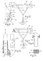
- FIG. 1 shows a part of the rear wheel 10 of a bicycle with a pneumatic tire 16 provided on a rim 14 held by spokes 12, which is spanned by a protective plate 17 and to which a rim brake 19 is assigned near a wheel fork 18.
- a luggage rack 20 is arranged over the section of the mudguard 17. This generally exists from a cover 24 fixed on two metal brackets 22 round or rectangular cross-section and a latter to a cuboid body - in the selected embodiment; a total length a of 440 mm, a height h of slightly more than 80 mm and a width b of about 140 mm - additional trough 26 which can be moved in the direction of travel x on the cover 24.
- the cover 24 is a molded material part with a support surface 28, from which project ribs 29 extending in the direction of travel x and which at both ends merge into end surfaces 30, 31 inclined outwards and upwards.
- the rear end surface 31 is part of a curved cross bead 32, which is clearly recognizable, for example, in FIG. 1 and is also provided with inclined lower edges 33.
- the front bow 36 of the luggage carrier 20 in the direction of travel x also tapers toward the front in a plan view according to FIG. 2 — above corresponding bow side surfaces 37 of the tub 26 — at an angle t of approximately 20 °.
- a flat and forwardly inclined front surface 38 adjoins the desk surface 30 of the bow 36 and abuts a bow degree 36m with a downwardly inclined lower bow surface 39.
- two slots 35 are indicated parallel to the support surface 28, into which the ends of lashing straps 40 are inserted. These close the slots 35 tightly.
- an angle iron 48 can be seen on the bow 36 of the cover 24, the free leg 49 of which serves to fix it to the wheel fork 18 at a distance i of, for example, 30 to 40 mm. Holes - possibly also oblong holes - are provided in the angle iron 48 for the use of screws.
- the tub 26 is equipped with a central longitudinal indentation 50 of its base plate 25, which protrudes into its interior 27, for receiving the bicycle mudguard 17 (FIG. 3) and on its side walls 52 with inwardly projecting edge nose strips 53, which are formed by guide rails 54 L formed on the cover 24 -shaped cross-section are reached and guided.
- This guide system 53/54 ends at the stop 45, from which the side walls 52 of the trough 26 continue bowward in accordance with the shape of the lid up to the bow lower surface 39 which is inclined approximately parallel to the wheel fork 18 as the bow side surfaces 37 already mentioned - and preferably slightly curved .
- a relatively large-area reflector 57 is attached in the rear surface 56 which delimits the tub 26 to the rear, and a cylinder lock 58, the key of which is designated 59 in FIG. 2, in the vertical axis M above it.
- a lock bolt 58 a engages in the closed position in a recess of the cover 24 which is not shown for reasons of clarity.
- a recessed grip 60 of the cover 24 extends below the transverse bead 36, a recessed grip of the trough 26 is indicated at 61.
- connection holes 64 - approximately T-shaped or keyhole-like in plan view - are formed in the plastic of the cover 24 or - in FIG. 24 indicated by a metal insert 62 - provided as attachment parts; in the wide section 64 b of each connection hole 64, the locking end 66 of a cross-sectionally T-shaped connecting body 67 can be used (FIG. 5), the length e of the locking end 66 corresponding approximately to the height of that wide section 64 b , to which a narrow slot part 64 e that connecting hole 64 connects.
- connection body 67 After the connection body 67 has been slightly shifted in the direction of travel x, its broad locking end 66 - for example the free end of a support rod 68 inserted into a pair of connection holes 64 according to FIG. 6 - engages behind the walls of the narrow slot part 64 e ; this is designed as an undercut groove.
- a respective connection hole 64 of the support surface 28 and a corresponding one of the side surface 63 are assigned to one another to form a common receiving space 65 for locking ends 66, namely above the guide rail 54 in a wide strip of material 70 of the cover 24, on whose - - The support surface 28 offering - ceiling 71 longitudinal ribs 72 are formed stabilizing.
- a locking pin 69 engages in that receiving space 65 and ends at the slot part 64 e in front of a locking pin 66 which may rest therein - the latter is now immovably fixed; the removal of the connection members 67 is only possible when the tub 26 is open.
- the side pocket 21 or the child seat is still attached to the luggage rack due to the elongated hole connection, since a movement in the longitudinal direction of the respective keyhole-like connection hole (here parallel to the longitudinal direction of the vehicle) is required to remove the side pocket or the child seat or the like subsequent lifting movement of the respective connector body 67 from the connector hole 64.
- Two further embodiments of the locking device for the connector holes 64 are explained below with reference to FIGS. 35 and 36.
- the luggage rack 20 can be easily mounted at a distance i to the wheel fork 18 (FIG. 10) or directly on it.
- the long leg 49 of the angle iron 48 of the tub 26 lies directly, that is to say loosely.
- the two bent metal brackets 22 of each carrier side are brought together in the region of their abutting plug ends 23 and are combined by a plug shoe 76 which is L-shaped in side view; the latter has a hole 77 eccentric at a distance j from the central axis N of the metal bracket 22, thanks to which the plug-in shoe 76 is fixed in the hub area of the bicycle with a screw 78.
- This distance j corresponds to half the cantilever length i of the angle iron 49, which considerably simplifies the assembly.
- the luggage carrier 20 is expediently fastened directly to the bicycle, in particular to the so-called Pletscher plate, in the region of the wheel fork 18 Using a variable-spacer intermediate piece, for example the angle iron 49, this is brought into its position close to the luggage rack (FIG. 11) and fixed to the pletcher plate.
- the plug-in shoe 76 is plugged on in the position shown in FIG. 11, that is to say with the hole 77 offset to the rear relative to the central axis N.
- the luggage carrier must be mounted on the two-wheeled vehicle offset backwards by a horizontal distance i so that there is sufficient space for the rim brake 19 between the wheel fork 18 and the inserted tray 26.
- the angle iron 49 is mounted on the cover 24 in its position remote from the luggage rack and offset by this distance i.
- the plug-in shoe 76 in one plugged by 180 ° around the central axis N to the plug ends 23 (FIG. 10), so that the hole 77 now lies in front of the central axis N by the distance j.
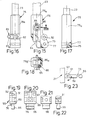
- the plug-in shoe 76 of the embodiment shown in FIGS. 13, 14 has a tubular part 76 a of rectangular cross section and - thus in one piece - a lateral flag 75 made of solid material (plastic injection molding).
- a ring-shaped insert made of metal with inwardly directed knobs 81 is designated, which can be inserted into corresponding recesses 23 a of the plug ends 23 and enable their length adjustment.
- the insert piece can be pushed over the tube part 76a and snapped on there; alternatively, the insert can also be inserted into the interior of the correspondingly oversized tube part 76 from above.
- the ring-like closed insert 80 can be elastically expanded in one direction or the other against spring force; the insert 80 can, however, also be slotted, in which case either a spring spring having a sufficiently strong spring-back is to be used or a reliable connection of the arrangement is to be ensured by a screw connection or a clamp arrangement.
- lateral notches 23b are arranged on the plug ends 23 for correspondingly arranged knobs 81.
- FIGS. 15 to 18 Another shoe 76 is provided, according to FIGS. 15 to 18, with a connecting eye 82 formed above the hole 77 for an unrecognizable mudguard strut; the latter is fixed by means of a special screw 83 offering a transverse hole 83 a .
- a connecting eye 82 formed above the hole 77 for an unrecognizable mudguard strut; the latter is fixed by means of a special screw 83 offering a transverse hole 83 a .
- an elongated hole 84 in the plug end 23 which is penetrated by an adjusting screw 85 in the region of a toothed pressure insert 86 made of steel, which also penetrates the tubular part 76 a .
- the pressure insert 86 or its teeth 86 a cut / cut into the softer material, preferably a light metal alloy, of the metal bracket 22, and in any length position of the plug ends 23. This enables a simple and quick stepless height adjustment of the, with little structural effort Porter.
- connecting elements are shown in FIGS. 19 ff.
- the latter can also be equipped directly with a pair of separate cast bodies 90 as connecting elements which are at a distance f from the pannier 21 or the like are set.
- This cast body 90 consists of the connecting element 76 with locking pin 66, a subsequent base piece 89 and a fastening part 92 articulated by means of an axis 91, which is connected to the packing bag 21 or the like.
- the cast body 90 is shown elongated and flat, but can also have a round cross section. It is fixed by means of screws, for example, on the pannier 21 or a corresponding additional part in such a way that the pivotable locking pin 66 can be inserted into one of the connection holes 64 described.
- the base piece can be designed as a threaded pin and screwed onto the additional part. Provision is also made to arrange the locking pins 66 at the end of an extension arm indicated at 89 a in FIG. 24.
- an integrally formed engagement strip 46 can be seen both on the transverse bead 32 and in the region of the desk surface 30.
- the bow is fixed here by means of an angle bracket 48a inserted into the cover 24 on the one hand.
- the plug ends 23 of the metal bracket 22 - which can also be formed on the plastic in special cases - are equipped in the manner already described with lateral outer grooves 23 b .
- the corresponding shoe 76 b receives the plug ends 23 in its laterally open interior space 79 b , which is then closed by means of a sliding cover 79.
- inner grooves 23 i are provided on the plug ends 23 for receiving a screw 78 i , or the like with its free end on the wheel fork 18. is fixed and also holds a support bracket 78 k releasably connecting the plug ends 23.
- the luggage rack 20 is also suitable for attachment to a front wheel 11 or the handlebar fork 13 of a bicycle or the like and in this case takes a headlight 55 instead of the reflector 57, the electrical connections of which are neglected in the drawing (FIG. 26). .
- the metal brackets 22 are connected to the wheel hub 15 with a plug-in shoe lug 75.
- Indicator lights 51 which are shown in FIG. 24, can be provided both in the last-described version and in the rear luggage rack 20. Any electronics required for this and for use as parking lights can be accommodated in the cover 24 without any problems.
- a handle 87 is arranged on the transverse bead 32 with transverse webs 87 a for the lashing straps 40.
- This handle 87 engages behind the lower edge 32 a of that transverse bead 32 with counter hooks 88 and is light therefrom separable, so that even superimposed loads 91a can be easily lashed (Fig. 32).
- Counter-toothing 92a on the lashing belt surfaces facing one another facilitates the longitudinal adjustment of the lashing belts 40.
- a simpler embodiment of the handle is designated by 87 n in FIGS. 30, 31, a spring clip 93 bent from wire offers both the transverse webs 87 a and the counter hooks 88.
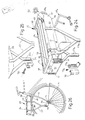
- FIG. 33 shows a further embodiment 120 of the luggage rack, components which correspond in function to those in the previous figures are provided with the same reference numbers, in each case increased by the number 100.
- the tub 126 at the rear end of which can be seen in FIG. 33, the rear reflector 157 (or a rear light or a headlight when mounting the luggage carrier on the front wheel) is to be attached.
- the rear reflector 157 or a rear light or a headlight when mounting the luggage carrier on the front wheel
- one of two turn signal lamps can be attached to the side surface, designated 200 in FIG. 33, which runs obliquely backwards and inwards.
- the cylinder lock 158 When assembled, the cylinder lock 158 is to be connected to a pivot bolt 202 indicated within the trough 126 by means of a split pin 204.
- the cover 124 is provided with a total of four pairs of two connection holes 164 each, the two rear pairs being selectively lockable by means of a single locking part 206 of a locking device 210 to be explained in more detail below with reference to FIG. 35.
- additional devices such as side pockets 21 or child seats, which use both front and rear connection holes 164
- the two bent metal brackets 122 of the two side rods are formed with an upper, horizontally angled end piece 212, with which they, after being inserted in a corresponding hole 164 on the bent-down side edge 216 of the cover 124, with which it is screwed by means of screws 214.
- the lower plug ends 123 of both metal brackets 122 when placed against one another, are inserted into the plug opening 218 of the respective plug shoe 176. Due to the elongated hole 184 at the plug end 123, there is the possibility of stepless height adjustment.
- the adjusting screw 185 engaging in the elongated hole 184 presses a toothed lock washer 223 on both sides of the insertion ends (similar construction as in FIGS. 16-18) in order to achieve a reliable positive connection in the selected height position.
- the plug shoe 176 can optionally be attached to the metal brackets 122 in one of the two possible orientations.
- the plug-in foot is designed with a horizontally running elongated hole 240 for receiving a screw 242 (e.g. wheel axle) which is used for fastening to the two-wheel frame.
- an angle 226 is used instead of the plate 220, which is accordingly designed with elongated holes and round holes for the fastening screws mentioned and also with a recess 228 in the upper leg for passage of the cable for the rim brake.
- spacer sleeves 230 can also be used which are penetrated by correspondingly long fastening screws 232.
- 33 also shows two short fastening screws 234 for the case of direct mounting on the two-wheel frame without a rear wheel rim brake.
- the cover 124 is fixed directly to the two tubes of the rear wheel fork via corresponding clamps 236.
- a metal U-profile 238 is indicated below the cover 124 at its right end, which is attached to the inside of the cover and serves as an abutment for the fastening screws (e.g. 232, 234).
- a connection body 167 can also be seen, which, according to the connection body 67 according to FIGS. 5 to 7, 22 and 23, can be part of a side pocket or the like and is locked on the cover 124 via the keyhole-like connection holes 164 can be.
- a rubber band (lashing cord) 140 can be seen at the top, which is guided through two slots 231 in the desk-like surface 130 rising from the front end of the cover 124, so that it lies between the holes 231 along the inside of the cover 124 extends and is thus fixed to the cover.
- the two free ends of the lashing cord 140 are wound several times onto the handle 187 with the outermost lashing cord end fixed in a slot 233.
- the multiple layers of the winding each penetrate a rectangular passage opening 235 in the handle, each of which has a laterally open slot 237 at its rear edge having. This makes it possible to unwind one or more layers of the winding one after the other or to wind up further layers in order to achieve the optionally change the effective length of the elastic band (lashing cord) 140. In this way, even large objects can be fixed on the luggage rack 120 without too much traction.
- the tub 126 is slidably mounted on the cover 124 via a profile rail 201.
- the profile rail 201 corresponds in cross section to a double-C profile, in the upper profile half of which the correspondingly designed peripheral edge 203 of the cover 124 is inserted in a form-fitting manner.
- the profile rail 201 runs along the entire outer circumference of the cover 124. In this way, it provides mechanical reinforcement of the cover 124 formed by a plastic part with an appealing exterior.
- the metal brackets 122 are directly coupled to the profile rail 201, in particular by means of threaded bolts 205 indicated in FIG.
- the lower half of the double-C profile is used in the region of the two opposite longitudinal side sections 213 of the profile rail 201, which are parallel to the direction of travel, to guide the correspondingly shaped tub edge 215 of the tub 126.
- the tub edge 215 is at the rear end of the respective one for leading out or in Longitudinal section 213 formed a milling 217 continuing the lower C-profile.
- In this area follows the horizontal one Long side section 213 a short, upward and rearward sloping section 219 of the profile rail 201, which then merges into the rear edge section 221 of the profile rail 201 which is perpendicular and horizontal to the direction of travel.
- a guide rail 301 is provided on each of the two long sides of the luggage carrier 210, on which both the cover 124 and the tub 126 are guided so as to be longitudinally displaceable. This enables the tub to be extended telescopically.
- the position 301 'of the guide rail 301 is indicated with a dashed outline with inserted tub and with a dash-dot line of position 301' 'in its outermost extended position 126' 'extended tub 126. Appropriate movement stops ensure that the tub and the guide rails 301 can no longer be pulled out.
- the tub 126 can be provided on its inside 126a with an angle profile rail 500, the upper leg 502 of which projects inwards.
- the rail 500 only extends along the two longitudinal edges of the tub and here stiffens the tub.
- the leg 502 is gripped by a leg 504, which is accordingly directed outwards, of an angled profile counter rail 506.
- the cross-sectionally Z-shaped rail 506 is attached to the underside of the cover 124.
- the rail 500 has an essentially L-profile cross section.
- the rail 506 can be screwed to the cover, which is indicated by a broken line 508.
- the vertical leg 510 of the rail 500 can be designed in a manner not shown with jags protruding downwards in order to keep the rail pressed together against the inside of the tub during manufacture 500 to improve with the tub body.
- the circumferential profile rail 201 is omitted.
- 35 shows the closing device 210 on the underside of the cover 124 with more details.
- a spring clip 240 in the form of a closed loop.
- Two relatively short, parallel to the extension direction A of the tub 128, opposite each other at the same height side legs 242 are each motion-coupled to one of the two slide-like closing parts 206, namely in that these two side legs 242 each penetrate a corresponding hole 244 of the closing part 206.
- the two closing parts 206 are linearly guided in a manner not shown with direction of movement B parallel to the plane of the cover and perpendicular to the direction of extension A of the tub 128.
- the connecting leg 246, which is at the rear in relation to the extension direction A (at the front in relation to the direction of travel) and connects the two side legs 242, is angled in a U-shape in the region of its longitudinal center (section 248) and is fixed with this section on the underside of the lid in a manner not shown (e.g. screwed tight). From this section 248 each run forward (in the direction of travel) and outwardly inclined sections 250 to the two side legs 244.
- the other (front) connecting leg 250 has a loop loop 252 in the region of its center length, which forms an elongated hole 254 parallel to the direction of movement A.
- the spring clip 240 assumes the shape indicated by the broken line in FIG. 35 without external force. This defines the open position of the locking device 210, in which the two locking parts 206 are retracted inwards (dashed position 206 '). In this position, they have moved out of the receiving space 260 within the cover 124 and below the respective pair of connection holes. It is therefore possible to move a connector body 167 indicated in FIG. 35 below from the area of the narrow hole section 262 into the area of the wide hole section 264 (in direction A) and then to move the head 266 located within the receiving space 260 through the wide one Pull out hole portion 264 through. As also shown in FIG. 33, the head 266 is seated on a neck 268.
- the head thickness (in direction B) corresponds essentially to the equally oriented width of the wide hole section 264; the equally oriented thickness of the neck 268 corresponds essentially to the equally oriented width of the narrow hole section 262, which results in the desired type of key connection.
- the tub 128 strikes (with its rear wall 270 on the lock side) on the spring clip 246 shortly before reaching the insertion position (in the area of the spring clip loop 252).
- the spring clip is increasingly deformed in such a way that the two connecting legs increasingly approach each other and, as a result, the two side legs 242 increasingly move away from one another.
- the two closing parts 206 are also increasingly pushed outward into the respective receiving space 260 until they finally assume the position shown with a solid line in FIG. 35 (closing position of the closing device 210 when the trough is pushed in). This inevitably results in a certain displacement of the two side legs 242 within the through holes 244 in the locking parts 206.
- the outer ends of the two locking parts 206 are located in the region of the end of the wide hole section 264 closest to the narrow hole section 262 and thus prevent the keyhole connection from being released by moving the connecting body from the narrow hole section to the wide hole section.
- 35A shows a further embodiment of the locking device, designated 610, in an exploded view.
- the two closing parts 606 which are mounted on the underside of the cover in the direction B in a manner not shown.
- both closing parts 606 engage in a slot 614 of a stamped sheet metal part 616 serving as a force transmission part, via a projection 612 projecting downwards.
- the stamped sheet metal part 616 is mounted on the underside of the cover in the direction A in a manner not shown.
- Both elongated holes 614 run in the direction A away from one another at an angle. If in the course of the insertion movement of the tub strikes the end 618 of the stamped sheet metal part 616 which is angled downwards on the left in FIG.
- closure covers can be attached to the cover 4, in particular by using the ultrasonic welding method.
- FIG. 36 shows an alternative embodiment of the locking device, designated 310.
- a double-arm lever 314 is pivotally mounted on the underside of the cover about an axis 312, the left arm of which is curved in a hook shape in FIG. 36 and serves as a closing part 306.
- the other arm 316 is used to control movement.
- this is done by abutment of the tub, in particular the tub rear wall 270 at the end of the insertion movement, so that the double-arm lever 314 from its initial position 314 ', again indicated by dashed lines in FIG. 36 (into which it is spring-biased in a manner not shown in detail) into the Solid line shown, the rotational position corresponding to the closed position of the locking device 310 is pivoted.
- the closing part 306 (hook end) in turn passes through the receiving space 260 such that a connection body (not shown) located in the narrow hole section cannot be moved into the wide hole section 264. In the starting position, however, the closing part 306 is pulled out of the receiving space 260.
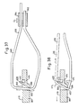
- Figures 37 and 38 show another type of lashing cord 340 and handle 387 with the possibility of a simple and quick change in the effective lashing cord length (between the attachment point on the cover, not shown, and the handle 387).
- the lashing cord 340 is guided relatively loosely through a slot 390 of the handle 387 and with its free end 392 fixed via a sliding part 394.
- the sliding part 294 can be freely pushed in the direction of the double arrow D along the strand section 396 between the cover and the handle 387 for the desired length adjustment. This almost doubles the unstretched length of section 296.
- the clamping lever 400 is connected in one piece to the handle 387 via a material constriction point 404 similar to a film hinge.
- the pivoting lever 400 is designed like a double arm, one arm being directed obliquely downward (in the direction of the cover) and towards the free end of the handle and ending in the clamping edge 398; the other arm runs in the opposite direction and protrudes beyond the top 410 of the handle 387.
- the lashing cord section 296 guided over the clamping lever 400 therefore tries to pivot the upper arm 412 of the double-arm lever 400 in FIG. 38 to the right with appropriate tension, which results in the desired tilting movement around the material constriction point 404 (directional arrows 414).
- a luggage rack for two-wheeled vehicles with a linkage provided on a support surface and extending to at least one fixed point on the two-wheeled vehicle, and with a drawer arranged under the support surface on slideways and displaceable in the longitudinal direction thereon consists of a cover fixed to the linkage and offering the support surface with at least one desk-like narrow side and one, on the lower surface of which there is a tub attached as a drawer in guide rails.
- an additional device in particular a side pocket, child seat or the like, can be detachably attached to the cover by means of a connector body attached to the additional device.
- a locking device for fixing the connection head on the cover is coupled to the trough in such a way that the trough moves the locking device into its closed position upon transition into its insertion position.
Landscapes
- Engineering & Computer Science (AREA)
- Mechanical Engineering (AREA)
- Fittings On The Vehicle Exterior For Carrying Loads, And Devices For Holding Or Mounting Articles (AREA)
- Automatic Cycles, And Cycles In General (AREA)
Priority Applications (2)
| Application Number | Priority Date | Filing Date | Title |
|---|---|---|---|
| AT89102681T ATE79809T1 (de) | 1988-02-16 | 1989-02-16 | Gepaecktraeger fuer zweiradfahrzeuge. |
| PCT/EP1989/000968 WO1990009304A1 (fr) | 1989-02-16 | 1989-08-16 | Porte-bagages pour vehicules a deux roues |
Applications Claiming Priority (2)
| Application Number | Priority Date | Filing Date | Title |
|---|---|---|---|
| DE3804753 | 1988-02-16 | ||
| DE3804753A DE3804753A1 (de) | 1988-02-16 | 1988-02-16 | Gepaecktraeger fuer zweiradfahrzeuge |
Publications (3)
| Publication Number | Publication Date |
|---|---|
| EP0329136A2 true EP0329136A2 (fr) | 1989-08-23 |
| EP0329136A3 EP0329136A3 (en) | 1990-03-21 |
| EP0329136B1 EP0329136B1 (fr) | 1992-08-26 |
Family
ID=6347487
Family Applications (1)
| Application Number | Title | Priority Date | Filing Date |
|---|---|---|---|
| EP89102681A Expired - Lifetime EP0329136B1 (fr) | 1988-02-16 | 1989-02-16 | Porte-bagages pour cycle |
Country Status (3)
| Country | Link |
|---|---|
| EP (1) | EP0329136B1 (fr) |
| AT (1) | ATE79809T1 (fr) |
| DE (3) | DE3804753A1 (fr) |
Cited By (6)
| Publication number | Priority date | Publication date | Assignee | Title |
|---|---|---|---|---|
| DE3935064A1 (de) * | 1989-10-20 | 1991-04-25 | Hans Kohler | Verschliessbare transportbox, insbesondere zur anbringung an einem zweiradgepaecktraeger |
| EP0625443A1 (fr) * | 1993-05-18 | 1994-11-23 | Michael Kleinecke | Conteneur portatif et siège combinés |
| EP1577201A1 (fr) * | 2004-03-18 | 2005-09-21 | Hamax As | Support pour bicyclette |
| NL1028808C2 (nl) * | 2005-04-19 | 2006-10-20 | Curana Bvba | Bagagedrager voor een rijwiel en werkwijze voor het vervaardigen van dergelijke bagagedrager. |
| EP4434861A1 (fr) * | 2023-03-24 | 2024-09-25 | Tenways Technovation Europe B.V. | Support arrière avec structure d'assemblage inclinée |
| WO2026076675A1 (fr) * | 2024-10-11 | 2026-04-16 | 浙江绿驹车业有限公司 | Dispositif de protection pour véhicule électrique modifié |
Families Citing this family (3)
| Publication number | Priority date | Publication date | Assignee | Title |
|---|---|---|---|---|
| DE9212659U1 (de) * | 1992-09-19 | 1993-01-28 | Prieschl, Herbert, 7117 Bretzfeld | Fahrradgepäckträger mit Stauraum fest montiert und abschließbar bzw. Fahrradgepäckträger mit abnehmbarem Taschenkörper zur Aufnahme von Gebrauchsgegenstände |
| TWI790906B (zh) * | 2022-01-27 | 2023-01-21 | 元毅工業股份有限公司 | 自行車貨架 |
| DE102024117101A1 (de) * | 2024-06-18 | 2025-12-18 | smartvélo mobility GmbH | Lochblech-gepäckträger mit abkantseiten als zuladungs- und aufbau-steck-/arretierungssystem und fahrrad mit gepäckträger |
Family Cites Families (5)
| Publication number | Priority date | Publication date | Assignee | Title |
|---|---|---|---|---|
| DE381803C (de) * | 1923-09-25 | Viktoria Werke A G | Anordnung des Werkzeugkastens an Fahrraedern u. dgl. | |
| US4266703A (en) * | 1980-01-28 | 1981-05-12 | Reuben Litz | Slide mount for motorcycle luggage box |
| DE8135492U1 (de) * | 1981-12-05 | 1982-06-16 | Vinz, Hannelore, 2105 Seevetal | Gepaecktraeger fuer fahrraeder |
| FR2546841B1 (fr) * | 1983-06-02 | 1990-03-16 | 3 B System | Dispositif de bagage pour motocyclettes ou similaires |
| DE3513878A1 (de) * | 1984-10-11 | 1986-04-17 | Henssler, Heinrich, 7070 Schwäbisch Gmünd | Zweirad-gepaecktraeger, insbesondere fahrrad-gepaecktraeger |
-
1988
- 1988-02-16 DE DE3804753A patent/DE3804753A1/de not_active Withdrawn
-
1989
- 1989-02-16 EP EP89102681A patent/EP0329136B1/fr not_active Expired - Lifetime
- 1989-02-16 DE DE8989102681T patent/DE58902100D1/de not_active Expired - Lifetime
- 1989-02-16 AT AT89102681T patent/ATE79809T1/de not_active IP Right Cessation
- 1989-02-16 DE DE8911873U patent/DE8911873U1/de not_active Expired - Lifetime
Cited By (7)
| Publication number | Priority date | Publication date | Assignee | Title |
|---|---|---|---|---|
| DE3935064A1 (de) * | 1989-10-20 | 1991-04-25 | Hans Kohler | Verschliessbare transportbox, insbesondere zur anbringung an einem zweiradgepaecktraeger |
| EP0625443A1 (fr) * | 1993-05-18 | 1994-11-23 | Michael Kleinecke | Conteneur portatif et siège combinés |
| EP1577201A1 (fr) * | 2004-03-18 | 2005-09-21 | Hamax As | Support pour bicyclette |
| NL1028808C2 (nl) * | 2005-04-19 | 2006-10-20 | Curana Bvba | Bagagedrager voor een rijwiel en werkwijze voor het vervaardigen van dergelijke bagagedrager. |
| BE1019016A3 (nl) * | 2005-04-19 | 2012-01-10 | Curana Invest Bvba | Bagagedrager voor een rijwiel en werkwijze voor het vervaardigen van dergelijke bagagedrager. |
| EP4434861A1 (fr) * | 2023-03-24 | 2024-09-25 | Tenways Technovation Europe B.V. | Support arrière avec structure d'assemblage inclinée |
| WO2026076675A1 (fr) * | 2024-10-11 | 2026-04-16 | 浙江绿驹车业有限公司 | Dispositif de protection pour véhicule électrique modifié |
Also Published As
| Publication number | Publication date |
|---|---|
| DE58902100D1 (de) | 1992-10-01 |
| ATE79809T1 (de) | 1992-09-15 |
| EP0329136A3 (en) | 1990-03-21 |
| EP0329136B1 (fr) | 1992-08-26 |
| DE3804753A1 (de) | 1989-08-24 |
| DE8911873U1 (de) | 1990-01-25 |
Similar Documents
| Publication | Publication Date | Title |
|---|---|---|
| DE69415538T2 (de) | Fahrradträger | |
| DE3301837A1 (de) | Vorrichtung zur anordnung eines aufbewahrungsbehaelters in einem kleinfahrzeug | |
| DE10003514A1 (de) | Kindersitz | |
| EP0019873B1 (fr) | Dispositif porte-bagages à fixer sur un toit de véhicule | |
| EP0329136B1 (fr) | Porte-bagages pour cycle | |
| DE9100567U1 (de) | Gepäckträger eines Zweirads | |
| DE3136897C2 (de) | Fahrzeug mit wenigstens einer Plane mit lösbarem Verschlußorgan en | |
| DE69406150T2 (de) | Dachgepäckträger, Skiträger oder ähnliches für Kraftfahrzeuge mit Dachreling | |
| WO1997008044A1 (fr) | Jeu de contenants | |
| DE2950449A1 (de) | Autolasttraeger | |
| DE19934384A1 (de) | Fahrrad-Träger zur lösbaren Befestigung an einem Fahrzeug | |
| DE3927086A1 (de) | Zubehoer fuer fahrzeuge und befestigungsvorrichtung dafuer, sowie herstellverfahren fuer einen adapter mit versteifung fuer das zubehoer | |
| DE10014291B4 (de) | Haken zur Befestigung von Behältnissen an Gepäckträgern und stangenförmiges Befestigungselement mit Haken | |
| DE202022003104U1 (de) | Lastenträgersystem für ein Kraftfahrzeug | |
| EP0413106A1 (fr) | Accessoires pour véhicules et dispositif de fixation à cet effet | |
| WO1990009304A1 (fr) | Porte-bagages pour vehicules a deux roues | |
| DE4029012A1 (de) | Fahrrad, abnehmbares bauteil eines fahrrades und zubehoer fuer ein zweirad | |
| DE10240463A1 (de) | Lastenträger zur Befestigung an einer Anhängerkupplung eines Kraftfahrzeuges mit Lastenträgeradapter für eine Anhängerdeichsel | |
| DE19720525C2 (de) | Plane für Lastfahrzeuge | |
| DE3935064A1 (de) | Verschliessbare transportbox, insbesondere zur anbringung an einem zweiradgepaecktraeger | |
| DE3024657A1 (de) | Vierraedriger kinderwagen, insbesondere kindersportwagen, mit zusammenklappbarem fahrgestell und in dieses einhaengbarer formsteifer liege- bzw. sitzschale | |
| DE69314862T2 (de) | Verriegelungsvorrichtung für motorrad | |
| WO1994011234A1 (fr) | Dispositif a fixer sur le cadre d'un vehicule a deux roues | |
| EP0629544B1 (fr) | Support de stationnement pour véhicules à deux roues, en particulier pour bicyclettes | |
| DE3912989A1 (de) | Aufsatzteil fuer eine traegerstange einer aussen an einem kraftfahrzeug anzubringenden traegerkonstruktion |
Legal Events
| Date | Code | Title | Description |
|---|---|---|---|
| PUAI | Public reference made under article 153(3) epc to a published international application that has entered the european phase |
Free format text: ORIGINAL CODE: 0009012 |
|
| AK | Designated contracting states |
Kind code of ref document: A2 Designated state(s): AT BE CH DE ES FR GB GR IT LI LU NL SE |
|
| PUAL | Search report despatched |
Free format text: ORIGINAL CODE: 0009013 |
|
| AK | Designated contracting states |
Kind code of ref document: A3 Designated state(s): AT BE CH DE ES FR GB GR IT LI LU NL SE |
|
| 17P | Request for examination filed |
Effective date: 19900418 |
|
| 17Q | First examination report despatched |
Effective date: 19901009 |
|
| GRAA | (expected) grant |
Free format text: ORIGINAL CODE: 0009210 |
|
| AK | Designated contracting states |
Kind code of ref document: B1 Designated state(s): AT BE CH DE ES FR GB GR IT LI LU NL SE |
|
| PG25 | Lapsed in a contracting state [announced via postgrant information from national office to epo] |
Ref country code: SE Free format text: THE PATENT HAS BEEN ANNULLED BY A DECISION OF A NATIONAL AUTHORITY Effective date: 19920826 Ref country code: NL Effective date: 19920826 Ref country code: IT Free format text: LAPSE BECAUSE OF FAILURE TO SUBMIT A TRANSLATION OF THE DESCRIPTION OR TO PAY THE FEE WITHIN THE PRE;WARNING: LAPSES OF ITALIAN PATENTS WITH EFFECTIVE DATE BEFORE 2007 MAY HAVE OCCURRED AT ANY TIME BEFORE 2007. THE CORRECT EFFECTIVE DATE MAY BE DIFFERENT FROM THE ONE RECORDED.SCRIBED TIME-LIMIT Effective date: 19920826 Ref country code: GR Free format text: LAPSE BECAUSE OF FAILURE TO SUBMIT A TRANSLATION OF THE DESCRIPTION OR TO PAY THE FEE WITHIN THE PRESCRIBED TIME-LIMIT Effective date: 19920826 Ref country code: GB Effective date: 19920826 Ref country code: ES Free format text: THE PATENT HAS BEEN ANNULLED BY A DECISION OF A NATIONAL AUTHORITY Effective date: 19920826 Ref country code: BE Effective date: 19920826 |
|
| REF | Corresponds to: |
Ref document number: 79809 Country of ref document: AT Date of ref document: 19920915 Kind code of ref document: T |
|
| REF | Corresponds to: |
Ref document number: 58902100 Country of ref document: DE Date of ref document: 19921001 |
|
| EN | Fr: translation not filed | ||
| PG25 | Lapsed in a contracting state [announced via postgrant information from national office to epo] |
Ref country code: FR Effective date: 19930115 |
|
| NLV1 | Nl: lapsed or annulled due to failure to fulfill the requirements of art. 29p and 29m of the patents act | ||
| PG25 | Lapsed in a contracting state [announced via postgrant information from national office to epo] |
Ref country code: AT Effective date: 19930216 |
|
| PG25 | Lapsed in a contracting state [announced via postgrant information from national office to epo] |
Ref country code: LU Free format text: LAPSE BECAUSE OF NON-PAYMENT OF DUE FEES Effective date: 19930228 Ref country code: LI Effective date: 19930228 Ref country code: CH Effective date: 19930228 |
|
| GBV | Gb: ep patent (uk) treated as always having been void in accordance with gb section 77(7)/1977 [no translation filed] |
Effective date: 19920826 |
|
| PLBE | No opposition filed within time limit |
Free format text: ORIGINAL CODE: 0009261 |
|
| STAA | Information on the status of an ep patent application or granted ep patent |
Free format text: STATUS: NO OPPOSITION FILED WITHIN TIME LIMIT |
|
| 26N | No opposition filed | ||
| REG | Reference to a national code |
Ref country code: CH Ref legal event code: AUV Free format text: DAS OBENGENANNTE PATENT IST, MANGELS BEZAHLUNG DER 5. JAHRESGEBUEHR, GELOESCHT WORDEN. Ref country code: CH Ref legal event code: PL |
|
| REG | Reference to a national code |
Ref country code: FR Ref legal event code: ST |
|
| PGFP | Annual fee paid to national office [announced via postgrant information from national office to epo] |
Ref country code: DE Payment date: 19950227 Year of fee payment: 7 |
|
| PG25 | Lapsed in a contracting state [announced via postgrant information from national office to epo] |
Ref country code: DE Effective date: 19961101 |