EP0329145B1 - Appareil pour entranier un membre porteur d'images - Google Patents
Appareil pour entranier un membre porteur d'images Download PDFInfo
- Publication number
- EP0329145B1 EP0329145B1 EP89102695A EP89102695A EP0329145B1 EP 0329145 B1 EP0329145 B1 EP 0329145B1 EP 89102695 A EP89102695 A EP 89102695A EP 89102695 A EP89102695 A EP 89102695A EP 0329145 B1 EP0329145 B1 EP 0329145B1
- Authority
- EP
- European Patent Office
- Prior art keywords
- image
- torque limiter
- bearing member
- driving
- image forming
- Prior art date
- Legal status (The legal status is an assumption and is not a legal conclusion. Google has not performed a legal analysis and makes no representation as to the accuracy of the status listed.)
- Expired - Lifetime
Links
- 238000004140 cleaning Methods 0.000 claims description 8
- 238000011144 upstream manufacturing Methods 0.000 claims description 3
- 230000005540 biological transmission Effects 0.000 claims 3
- 239000011800 void material Substances 0.000 claims 1
- 230000005856 abnormality Effects 0.000 description 15
- 238000007599 discharging Methods 0.000 description 14
- 238000000034 method Methods 0.000 description 11
- 238000010276 construction Methods 0.000 description 7
- 230000006378 damage Effects 0.000 description 5
- 230000002093 peripheral effect Effects 0.000 description 5
- 239000002699 waste material Substances 0.000 description 3
- 230000000694 effects Effects 0.000 description 2
- 238000009434 installation Methods 0.000 description 2
- 230000002159 abnormal effect Effects 0.000 description 1
- 238000001514 detection method Methods 0.000 description 1
- 230000000977 initiatory effect Effects 0.000 description 1
- 230000003287 optical effect Effects 0.000 description 1
- 230000002028 premature Effects 0.000 description 1
- 230000035945 sensitivity Effects 0.000 description 1
Images

Classifications
-
- G—PHYSICS
- G03—PHOTOGRAPHY; CINEMATOGRAPHY; ANALOGOUS TECHNIQUES USING WAVES OTHER THAN OPTICAL WAVES; ELECTROGRAPHY; HOLOGRAPHY
- G03G—ELECTROGRAPHY; ELECTROPHOTOGRAPHY; MAGNETOGRAPHY
- G03G15/00—Apparatus for electrographic processes using a charge pattern
- G03G15/75—Details relating to xerographic drum, band or plate, e.g. replacing, testing
- G03G15/757—Drive mechanisms for photosensitive medium, e.g. gears
Definitions
- the present invention relates to an image forming apparatus such as a copying machine, printer and the like, in which an image is formed through a predetermined processes by forming a latent image on an image bearing member such as a photosensitive drum, by visualizing the latent image by using a developer in a developing device, by transferring the visualized image from the image bearing member onto a transfer member and then by fixing the transferred image. More particularly, the present invention relates to an image forming apparatus which can prematurely detect abnormality in driving apparatuses for driving an image bearing member such as a photosensitive drum and a developing device to effectively prevent damage or destruction of the image forming apparatus and which includes a compact driving apparatus adapted to drive such image bearing member and the like.
- an image forming apparatus such as a copying machine, printer and the like, in which an image is formed through predetermined processes by forming a latent image on an image bearing member such as a photosensitive drum, by visualizing the latent image by using a developer in a developing device, by transferring the visualized image from the image bearing member onto a transfer member, by fixing the tranferred image, and by cleaning the residual developer on the image bearing member by means of a cleaner
- the above-mentioned predetermined processes such as the latent image forming process, image visualizing process, image transferring process and the like necessary to form the image were carried out by rotating image bearing member such as the photosensitive drum constituted by an endless belt or a rotatable drum.
- the driving apparatuses for driving or rotating the image forming member such as the photosensitive drum (hereinafter, referring to the driving apparatuses associated with the photosensitive drum), a mechanism comprising a gear fixed to a flange of the photosensitive drum and a gear connected to a driving source so that the photosensitive drum is rotated by the driving source, or a mechanism wherein a photosensitive drum driving plate arranged coaxially with a support shaft for the photosensitive drum is rotated in such a manner that a pin fixed to the driving plate engages with and entrains a flange of the photosensitive drum to rotate the latter have been used. Further, the developing device used in the image visualizing process was driven through the gear fixed to the flange of the photosensitive drum or by means of a discrete driving mechanism for driving the developing device.
- driving apparatuses had a torque limiter for limiting an upper limit of a driving torque to prevent the damage of the image forming apparatus when abnormality occurred in load torques regarding the photosensitive drum, developing device, cleaner and the like.
- driving apparatus was used in a container for receiving a waste or exhaust toner to prevent the damage of a toner discharging member provided in the container, which would be caused during the rotation of the toner discharging member when the container was filled with the toner.
- the torque limiter for detecting the abnormity in the load torque when the torque limiter for detecting the abnormity in the load torque is arranged upstream of the driving system for the photosensitive drum, the torque limiter cannot detect the abnormity in the load torques unless the capacity of the torque limiter is set to be larger than all of the load torques in the downstream side of the photosensitive drum, thus increasing an error regarding the operating torque of the limiter.
- the torque limiter if the abnormality in the load torques is detected by using such larger operating torque, for example, when the abnormality occurs in a cleaner having the toner discharging member, upon the detection of the abnormality, there will be greater possibility of occurring of serious or critical damage of the cleaner, with the result that, in the worst case, the cleaner unit must be replaced.
- the cleaner unit and the like are previously constructed more strongly for providing against such abnormality; however, such countermeasure is not desirable from the view point of the available space in the image forming apparatus, the cost of the constructural parts and the like.
- the abnormity in the cleaner can be positively detected; however, in this case, since the abnormity in the cleaner is signaled to an operator only by an abnormal noise, if the operator continues a copying operation without being aware of the abnormity, the toner will overflow out of the cleaner to smear the interior of the image forming apparatus.
- the above-mentioned drawback can be eliminated by arranging the torque limiter upstream of the driving system for the photosensitive drum; however, in this case, since the discrete driving mechanism is added, there arose a problem that the number of the constructural parts of the image forming apparatus is increased and that the apparatus cannot be easily compacted.
- It is another object of the present invention is to provide an image forming apparatus including a driving apparatus which can drive a plurality of elements such as a developing device, a waste toner discharging member and the like, as well as an image bearing member such as a photosensitive drum by a compact driving means including a torque limiter to form an image, and wherein a torque value of the torque limiter can be set to positively detect abnormality in even lower load torque.
- a driving apparatus which can drive a plurality of elements such as a developing device, a waste toner discharging member and the like, as well as an image bearing member such as a photosensitive drum by a compact driving means including a torque limiter to form an image, and wherein a torque value of the torque limiter can be set to positively detect abnormality in even lower load torque.
- a driving apparatus adapted to be used with an image forming apparatus which can form an image on an image bearing member through predetermined image forming processes, and capable of drivingly rotating the image bearing member by means of a driving means including a torque limiter arranged coaxially with a shaft for supporting the image bearing member.
- the driving apparatus includes a driving means for directly transmitting a driving force from a driving source in order to directly drive a developing device used in the predetermined image forming processes.
- the driving means including the torque limiter arranged coaxially with the support shaft for supporting the image bearing member, and by arranging, in parallel with said driving means, the discrete driving means for directly transmitting the driving force from the driving source in order to drive the developing device, it is possible to positively perform the operation of the torque limiter and to set the value of the torque limiter in high response to the photosensitive drum and to provide a compact construction. Further, by stopping the rotation of the photosensitive drum as the image bearing member when the torque limiter is operated, it is possible to positively signal the abnormality to the operator.
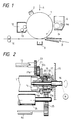
- Fig. 1 shows a preferred embodiment of an image forming apparatus according to the present invention.
- the image forming apparatus shown in Fig. 1 comprises an electrophotographic photosensitive drum 1 as an image bearing member, which is formed in a cylindrical shape and is rotated in a direction shown by an arrow in Fig. 1.
- a charging device 2 for uniformly charging a peripheral surface of the photosensitive drum 1
- a known developing device 6 for visualizing the latent image by applying a toner as a developer to the latent image formed on the photosensitive drum 1
- a transfer charging device 8 for transferring the visualized image from the photosensitive drum 1 onto a transfer sheet P such as a paper
- a known fixing device 10 for fixing the image transferred to the transfer sheet P
- a cleaning device 12 for cleaning the residual toner on the photosensitive drum 1.
- the cleaning device 12 includes a to
- Image forming processes carried out by the image forming apparatus having the construction mentioned above are well known in the art; and, thus, the detailed explanation regarding the image forming processes will be omitted here.
- the photosensitive drum 1 has a flange 14 fixed thereto, on an outer peripheral surface of which a gear 14a for transmitting a driving force to the toner discharging member 13 is formed.
- the flange 14 is rotatably supported, at its central portion, by a support shaft 16 rotatably mounted on a frame 15 of the image forming apparatus. Accordingly, the photosensitive drum 1 is freely rotatably supported by the frame 15 through the support shaft 16.
- a substantially cylindrical gear 17 acting as a driving means is fixed to the support shaft 16 coaxially therewith.
- a coil spring 18, a ring-shaped limiter plate 19 and a substantially circular driving plate 20 having a step are incorporated in the gear 17 in a predetermined position, which elements 18-20 constitute a torque limiter 17A as a whole.
- a pin 20a protruded from the driving plate 20 of the torque limiter 17A toward the flange 14 can engage by one of ribs 14b (Fig. 4) formed in the flange 14.
- the gear 14a formed on the peripheral surface of the flange 14 meshes with an idler gear 21 having a small gear 21a fixed thereto, which meshes with a driving gear 23 for driving the toner discharging member 13.
- a gear portion 17a formed on an outer peripheral surface of the gear 17 meshes with a sleeve gear 25 fixed to a developing sleeve 24.
- three grooves 17b are formed in an inner peripheral surface of the substantially cylindrical gear 17 acting as the driving means in predetermined positions, and these grooves 17a are engaged by corresponding pawls 19b formed on an outer periphery of the limiter plate 19 in predetermined positions; thus, when assembled, the limiter plate 19 can be slidably moved along a central axis of the gear 17 while engaging by the grooves 17b.
- three trapezoidal projections 19a are formed on an outer side surface of the limiter plate 19 in predetermined positions, which projections are engaged by corresponding trapezoidal recesses 20b formed in an inner side surface of the driving plate 20.
- the driving plate 20 has an outer diameter that the driving plate is fitted in the gear 17.
- the limiter plate 19 cannot escape from the recesses 20b and thus transmits the rotational force to the driving plate 20.
- a torque value for creating the operation condition of the torque limiter 17A can be properly set by appropriately selecting an angle of the inclined surface of the projection (and recess), coefficient of friction between the projection and recess, and the force of the coil spring 18.
- the driving force is transmitted to the coil spring 18, limiter plate 19, driving plate 20 and pin 20a in order, with the result that the pin 20a drivingly rotates the flange 14 and the photosensitive drum 1 through the engagement between the pin 20a and the rib 14b (Fig. 4) of the flange 14.
- the gear 14a formed on the outer periphery of the flange 14 meshes with the idler gear 21, the driving gear 23 for driving the toner discharging member 13 for conveying the residual toner removed by the cleaner to the predetermined collection position is also rotated through the idler gear 21 and its small gear 21a. Accordingly, in this case, the load torques form the photosensitive drum 1 and the toner discharging member 13 are applied to the pin 20a of the torque limiter 17A.
- the load torque of the photosensitive drum 1 and the toner discharging member 13 is 4 ⁇ 0.5 kg ⁇ cm
- the load torque of the developing device 6 is 4 ⁇ 1.5 kg ⁇ cm
- the load torques created when the toner container is filled with the toner can be detected by the torque limiter having the set torque value of 5 ⁇ 0.5 kg ⁇ cm.
- it is possible to detect the abnormality with a maximum error of 2 kg ⁇ cm ((5.5 - 3.5)kg ⁇ cm).
- the torque value of the torque limiter used must be set to 11 ⁇ 1.1 kg ⁇ cm.
- the present invention is not limited to the illustrated embodiment wherein the torque limiter is assembled in the substantially cylindrical gear.
- the torque limiter may be assembled in the flange 14 of the photosensitive drum 1.
- the torque limiter does not depend upon the type thereof, but depends upon only the installation position thereof.
- the effect obtainable from the present invention does not depend upon the configuration of the photosensitive drum (image bearing member). For example, as shown in Fig. 5, even when an electrophotographic photosensitive belt 1a entrained around a flange 26 (in place of the flange 14 of the drum) on which the torque limiter acts is used, a satisfactory effect can be obtained.
- the photosensitive drum as the image bearing member is driven by the gear acting as the driving means having the torque limiter arranged coaxially with the support shaft for the photosensitive drum and the driving gear for directly transmitting the driving force from the driving source in order to drive the developing device is associated with the first-mentioned gear, it is possible to set the torque value of the torque limiter in higher response to the photosensitive drum than in the conventional case, whereby the abnormity in the load torque of the photosensitive drum can be prematurely detected and can be signaled to the operator positively. Further, since the photosensitive drum and the developing device can be driven by the single driving mechanism, the whole dimension of the image forming apparatus can be considerably reduced.
Landscapes
- Physics & Mathematics (AREA)
- General Physics & Mathematics (AREA)
- Discharging, Photosensitive Material Shape In Electrophotography (AREA)
- Electrophotography Configuration And Component (AREA)
- Dry Development In Electrophotography (AREA)
- Cleaning In Electrography (AREA)
Claims (6)
- Appareil de formation d'images destiné à enregistrer une image sur un support d'enregistrement (P), comportant
une source d'entraînement (M),
un élément tournant (1) porteur d'image, ledit élément porteur d'image ayant une partie (14) de réception recevant une force d'entraînement de ladite source d'entraînement, et
des moyens (16-20, 14, 21, 23) de transmission de force d'entraînement destinés à transmettre la force d'entraînement de ladite source (M) d'entraînement à ladite partie de réception (14), lesdits moyens de transmission d'entraînement ayant un limiteur de couple (17A), dans lequel ledit limiteur de couple (17A) restreint la transmission de la force d'entraînement de ladite source (M) d'entraînement à ladite partie de réception (14) lorsqu'une surcharge est générée en aval dudit limiteur de couple (17A) dans le sens de transmission de la force d'entraînement,
caractérisé par
un moyen de nettoyage (12) destiné à enlever un développateur dudit élément (1) porteur d'image, ledit moyen de nettoyage (12) ayant une partie contenante destinée à contenir le développateur enlevé dudit élément porteur d'image, et un élément de transport (13) destiné à transporter le développateur jusqu'à ladite partie contenante, ledit élément (13) de transport recevant la force d'entraînement à travers ladite partie (14) de réception. - Appareil de formation d'images selon la revendication 1, dans lequel ledit limiteur (17A) de couple restreint la transmission de la force d'entraînement de la source (M) d'entraînement à ladite partie (14) de réception lorsque le développateur transporté vers ladite partie contenante augmente jusqu'à une quantité prédéterminée.
- Appareil de formation d'images selon la revendication 1, dans lequel ledit limiteur (17A) de couple comporte un ressort (18), une plaque (19) de limitation et une plaque (20) d'entraînement.
- Appareil de formation d'images selon la revendication 1, dans lequel ledit élément (1) porteur d'image tourne irrégulièrement lorsque ledit limiteur (17A) de couple est en action.
- Appareil de formation d'images selon la revendication 4, comportant en outre des moyens (2, 4, 6) de formation d'image destinés à former une image développée sur ledit élément (1) porteur d'image, et des moyens (8) de report destinés à reporter l'image développée portée par ledit élément (1) porteur d'image sur le support (P) d'enregistrement, ledit appareil de formation d'images formant une image dépourvue par intermittence de l'image développée sur le support d'enregistrement.
- Appareil de formation d'images selon la revendication 1, comportant en outre des moyens (6) de développement destinés à fournir le développateur audit élément (1) porteur d'image, lesdits moyens de développement recevant la force d'entraînement de ladite source (M) d'entraînement en amont dudit limiteur (17A) de couple dans le sens de transmission de la force d'entraînement.
Applications Claiming Priority (2)
| Application Number | Priority Date | Filing Date | Title |
|---|---|---|---|
| JP63038320A JP2711334B2 (ja) | 1988-02-19 | 1988-02-19 | 画像形成装置 |
| JP38320/88 | 1988-02-19 |
Publications (3)
| Publication Number | Publication Date |
|---|---|
| EP0329145A2 EP0329145A2 (fr) | 1989-08-23 |
| EP0329145A3 EP0329145A3 (en) | 1989-12-06 |
| EP0329145B1 true EP0329145B1 (fr) | 1994-12-07 |
Family
ID=12521994
Family Applications (1)
| Application Number | Title | Priority Date | Filing Date |
|---|---|---|---|
| EP89102695A Expired - Lifetime EP0329145B1 (fr) | 1988-02-19 | 1989-02-16 | Appareil pour entranier un membre porteur d'images |
Country Status (4)
| Country | Link |
|---|---|
| EP (1) | EP0329145B1 (fr) |
| JP (1) | JP2711334B2 (fr) |
| DE (1) | DE68919721T2 (fr) |
| IT (1) | IT1230821B (fr) |
Families Citing this family (7)
| Publication number | Priority date | Publication date | Assignee | Title |
|---|---|---|---|---|
| EP0443461B1 (fr) * | 1990-02-17 | 1994-08-24 | Canon Kabushiki Kaisha | Unité de traitement et appareil de formation d'images utilisant une telle unité |
| JPH0440244U (fr) * | 1990-07-30 | 1992-04-06 | ||
| ES2086736T3 (es) * | 1991-04-10 | 1996-07-01 | Canon Kk | Cartucho de proceso y metodo para el montaje de dicho cartucho de proceso. |
| EP0813119B1 (fr) * | 1992-06-30 | 2001-04-11 | Canon Kabushiki Kaisha | Cartouche de traitement et système de formation d'image |
| US5701565A (en) * | 1996-03-29 | 1997-12-23 | Xerox Corporation | Web feed printer drive system |
| KR100544456B1 (ko) | 2003-10-20 | 2006-01-24 | 삼성전자주식회사 | 기어어셈블리 및 이를 구비한 감광유닛 |
| JP7034651B2 (ja) * | 2017-09-28 | 2022-03-14 | キヤノン株式会社 | 画像形成装置 |
Family Cites Families (5)
| Publication number | Priority date | Publication date | Assignee | Title |
|---|---|---|---|---|
| US4327992A (en) * | 1980-07-10 | 1982-05-04 | Apeco Corporation | Driving arrangement for photocopy machine |
| JPS60188627A (ja) * | 1984-03-05 | 1985-09-26 | Konishiroku Photo Ind Co Ltd | 複写機等における駆動伝達装置 |
| JPS60150567U (ja) * | 1984-03-14 | 1985-10-05 | シャープ株式会社 | トナ−量検出装置 |
| JPS60247279A (ja) * | 1984-05-22 | 1985-12-06 | Sanyo Electric Co Ltd | 電子複写機 |
| JPS62279355A (ja) * | 1986-05-28 | 1987-12-04 | Konica Corp | カラ−画像形成装置 |
-
1988
- 1988-02-19 JP JP63038320A patent/JP2711334B2/ja not_active Expired - Fee Related
-
1989
- 1989-02-16 EP EP89102695A patent/EP0329145B1/fr not_active Expired - Lifetime
- 1989-02-16 DE DE68919721T patent/DE68919721T2/de not_active Expired - Fee Related
- 1989-02-17 IT IT8947663A patent/IT1230821B/it active
Also Published As
| Publication number | Publication date |
|---|---|
| EP0329145A2 (fr) | 1989-08-23 |
| JP2711334B2 (ja) | 1998-02-10 |
| DE68919721D1 (de) | 1995-01-19 |
| JPH01211773A (ja) | 1989-08-24 |
| EP0329145A3 (en) | 1989-12-06 |
| DE68919721T2 (de) | 1995-05-18 |
| IT8947663A0 (it) | 1989-02-17 |
| IT1230821B (it) | 1991-11-07 |
Similar Documents
| Publication | Publication Date | Title |
|---|---|---|
| US5303004A (en) | Apparatus for driving image bearing member via torque limiter | |
| US7103308B2 (en) | Developer cartridge and image forming apparatus | |
| US4620783A (en) | Color image forming apparatus | |
| EP0331324B1 (fr) | Appareil de formation d'images avec cartouche de traitement amovible | |
| EP0329145B1 (fr) | Appareil pour entranier un membre porteur d'images | |
| US4586813A (en) | Image forming apparatus | |
| JPH11288191A (ja) | 画像形成装置 | |
| KR100497397B1 (ko) | 화상형성시스템에 있어서 용지픽업 제어방법 및 장치 | |
| JPH05119551A (ja) | プロセスカートリツジ駆動機構及び画像形成装置 | |
| JP2000162945A (ja) | プロセスカートリッジ及び画像形成装置 | |
| CN110217621A (zh) | 分离辊、片材进给设备、和成像设备 | |
| JP2000066556A (ja) | 廃トナー搬送装置および画像形成装置 | |
| JP3673642B2 (ja) | 定着装置 | |
| JP3422543B2 (ja) | 電子写真感光体の駆動装置 | |
| JPH0721290B2 (ja) | 記録装置等の駆動伝達装置 | |
| GB2057305A (en) | Magnetic brush developing device | |
| JP2000019798A (ja) | 定着装置及びこの定着装置を備える画像形成装置 | |
| JP2503449B2 (ja) | 画像形成装置 | |
| JP7521200B2 (ja) | 画像形成装置 | |
| KR100601723B1 (ko) | 화상형성장치 | |
| JPH07243511A (ja) | 伝動装置 | |
| JPH01164975A (ja) | 現像装置 | |
| JPS62127785A (ja) | 感光ドラムの装着方法 | |
| JPS61141475A (ja) | 画像形成装置 | |
| JPH07117801B2 (ja) | トナー搬送機構及びプロセスカートリッジ |
Legal Events
| Date | Code | Title | Description |
|---|---|---|---|
| PUAI | Public reference made under article 153(3) epc to a published international application that has entered the european phase |
Free format text: ORIGINAL CODE: 0009012 |
|
| AK | Designated contracting states |
Kind code of ref document: A2 Designated state(s): DE FR GB |
|
| PUAL | Search report despatched |
Free format text: ORIGINAL CODE: 0009013 |
|
| AK | Designated contracting states |
Kind code of ref document: A3 Designated state(s): DE FR GB |
|
| 17P | Request for examination filed |
Effective date: 19900423 |
|
| 17Q | First examination report despatched |
Effective date: 19920629 |
|
| GRAA | (expected) grant |
Free format text: ORIGINAL CODE: 0009210 |
|
| AK | Designated contracting states |
Kind code of ref document: B1 Designated state(s): DE FR GB |
|
| REF | Corresponds to: |
Ref document number: 68919721 Country of ref document: DE Date of ref document: 19950119 |
|
| ET | Fr: translation filed | ||
| PLBE | No opposition filed within time limit |
Free format text: ORIGINAL CODE: 0009261 |
|
| STAA | Information on the status of an ep patent application or granted ep patent |
Free format text: STATUS: NO OPPOSITION FILED WITHIN TIME LIMIT |
|
| 26N | No opposition filed | ||
| REG | Reference to a national code |
Ref country code: GB Ref legal event code: IF02 |
|
| PGFP | Annual fee paid to national office [announced via postgrant information from national office to epo] |
Ref country code: DE Payment date: 20070208 Year of fee payment: 19 |
|
| PGFP | Annual fee paid to national office [announced via postgrant information from national office to epo] |
Ref country code: GB Payment date: 20070214 Year of fee payment: 19 |
|
| PGFP | Annual fee paid to national office [announced via postgrant information from national office to epo] |
Ref country code: FR Payment date: 20070208 Year of fee payment: 19 |
|
| GBPC | Gb: european patent ceased through non-payment of renewal fee |
Effective date: 20080216 |
|
| REG | Reference to a national code |
Ref country code: FR Ref legal event code: ST Effective date: 20081031 |
|
| PG25 | Lapsed in a contracting state [announced via postgrant information from national office to epo] |
Ref country code: DE Free format text: LAPSE BECAUSE OF NON-PAYMENT OF DUE FEES Effective date: 20080902 |
|
| PG25 | Lapsed in a contracting state [announced via postgrant information from national office to epo] |
Ref country code: FR Free format text: LAPSE BECAUSE OF NON-PAYMENT OF DUE FEES Effective date: 20080229 |
|
| PG25 | Lapsed in a contracting state [announced via postgrant information from national office to epo] |
Ref country code: GB Free format text: LAPSE BECAUSE OF NON-PAYMENT OF DUE FEES Effective date: 20080216 |