EP0329157A2 - Steuergerät für die Dicke einer Schicht - Google Patents
Steuergerät für die Dicke einer Schicht Download PDFInfo
- Publication number
- EP0329157A2 EP0329157A2 EP89102761A EP89102761A EP0329157A2 EP 0329157 A2 EP0329157 A2 EP 0329157A2 EP 89102761 A EP89102761 A EP 89102761A EP 89102761 A EP89102761 A EP 89102761A EP 0329157 A2 EP0329157 A2 EP 0329157A2
- Authority
- EP
- European Patent Office
- Prior art keywords
- thickness
- time
- film
- state
- value
- Prior art date
- Legal status (The legal status is an assumption and is not a legal conclusion. Google has not performed a legal analysis and makes no representation as to the accuracy of the status listed.)
- Granted
Links
Images












Classifications
-
- G—PHYSICS
- G05—CONTROLLING; REGULATING
- G05D—SYSTEMS FOR CONTROLLING OR REGULATING NON-ELECTRIC VARIABLES
- G05D5/00—Control of dimensions of material
- G05D5/02—Control of dimensions of material of thickness, e.g. of rolled material
- G05D5/03—Control of dimensions of material of thickness, e.g. of rolled material characterised by the use of electric means
-
- B—PERFORMING OPERATIONS; TRANSPORTING
- B29—WORKING OF PLASTICS; WORKING OF SUBSTANCES IN A PLASTIC STATE IN GENERAL
- B29C—SHAPING OR JOINING OF PLASTICS; SHAPING OF MATERIAL IN A PLASTIC STATE, NOT OTHERWISE PROVIDED FOR; AFTER-TREATMENT OF THE SHAPED PRODUCTS, e.g. REPAIRING
- B29C48/00—Extrusion moulding, i.e. expressing the moulding material through a die or nozzle which imparts the desired form; Apparatus therefor
- B29C48/03—Extrusion moulding, i.e. expressing the moulding material through a die or nozzle which imparts the desired form; Apparatus therefor characterised by the shape of the extruded material at extrusion
- B29C48/07—Flat, e.g. panels
- B29C48/08—Flat, e.g. panels flexible, e.g. films
-
- B—PERFORMING OPERATIONS; TRANSPORTING
- B29—WORKING OF PLASTICS; WORKING OF SUBSTANCES IN A PLASTIC STATE IN GENERAL
- B29C—SHAPING OR JOINING OF PLASTICS; SHAPING OF MATERIAL IN A PLASTIC STATE, NOT OTHERWISE PROVIDED FOR; AFTER-TREATMENT OF THE SHAPED PRODUCTS, e.g. REPAIRING
- B29C48/00—Extrusion moulding, i.e. expressing the moulding material through a die or nozzle which imparts the desired form; Apparatus therefor
- B29C48/25—Component parts, details or accessories; Auxiliary operations
- B29C48/92—Measuring, controlling or regulating
-
- G—PHYSICS
- G05—CONTROLLING; REGULATING
- G05B—CONTROL OR REGULATING SYSTEMS IN GENERAL; FUNCTIONAL ELEMENTS OF SUCH SYSTEMS; MONITORING OR TESTING ARRANGEMENTS FOR SUCH SYSTEMS OR ELEMENTS
- G05B13/00—Adaptive control systems, i.e. systems automatically adjusting themselves to have a performance which is optimum according to some preassigned criterion
- G05B13/02—Adaptive control systems, i.e. systems automatically adjusting themselves to have a performance which is optimum according to some preassigned criterion electric
- G05B13/0205—Adaptive control systems, i.e. systems automatically adjusting themselves to have a performance which is optimum according to some preassigned criterion electric not using a model or a simulator of the controlled system
- G05B13/026—Adaptive control systems, i.e. systems automatically adjusting themselves to have a performance which is optimum according to some preassigned criterion electric not using a model or a simulator of the controlled system using a predictor
-
- B—PERFORMING OPERATIONS; TRANSPORTING
- B29—WORKING OF PLASTICS; WORKING OF SUBSTANCES IN A PLASTIC STATE IN GENERAL
- B29C—SHAPING OR JOINING OF PLASTICS; SHAPING OF MATERIAL IN A PLASTIC STATE, NOT OTHERWISE PROVIDED FOR; AFTER-TREATMENT OF THE SHAPED PRODUCTS, e.g. REPAIRING
- B29C2948/00—Indexing scheme relating to extrusion moulding
- B29C2948/92—Measuring, controlling or regulating
- B29C2948/92009—Measured parameter
- B29C2948/92114—Dimensions
- B29C2948/92152—Thickness
-
- B—PERFORMING OPERATIONS; TRANSPORTING
- B29—WORKING OF PLASTICS; WORKING OF SUBSTANCES IN A PLASTIC STATE IN GENERAL
- B29C—SHAPING OR JOINING OF PLASTICS; SHAPING OF MATERIAL IN A PLASTIC STATE, NOT OTHERWISE PROVIDED FOR; AFTER-TREATMENT OF THE SHAPED PRODUCTS, e.g. REPAIRING
- B29C2948/00—Indexing scheme relating to extrusion moulding
- B29C2948/92—Measuring, controlling or regulating
- B29C2948/92323—Location or phase of measurement
- B29C2948/92428—Calibration, after-treatment, or cooling zone
-
- B—PERFORMING OPERATIONS; TRANSPORTING
- B29—WORKING OF PLASTICS; WORKING OF SUBSTANCES IN A PLASTIC STATE IN GENERAL
- B29C—SHAPING OR JOINING OF PLASTICS; SHAPING OF MATERIAL IN A PLASTIC STATE, NOT OTHERWISE PROVIDED FOR; AFTER-TREATMENT OF THE SHAPED PRODUCTS, e.g. REPAIRING
- B29C2948/00—Indexing scheme relating to extrusion moulding
- B29C2948/92—Measuring, controlling or regulating
- B29C2948/92504—Controlled parameter
- B29C2948/9258—Velocity
- B29C2948/926—Flow or feed rate
-
- B—PERFORMING OPERATIONS; TRANSPORTING
- B29—WORKING OF PLASTICS; WORKING OF SUBSTANCES IN A PLASTIC STATE IN GENERAL
- B29C—SHAPING OR JOINING OF PLASTICS; SHAPING OF MATERIAL IN A PLASTIC STATE, NOT OTHERWISE PROVIDED FOR; AFTER-TREATMENT OF THE SHAPED PRODUCTS, e.g. REPAIRING
- B29C2948/00—Indexing scheme relating to extrusion moulding
- B29C2948/92—Measuring, controlling or regulating
- B29C2948/92504—Controlled parameter
- B29C2948/92609—Dimensions
- B29C2948/92647—Thickness
-
- B—PERFORMING OPERATIONS; TRANSPORTING
- B29—WORKING OF PLASTICS; WORKING OF SUBSTANCES IN A PLASTIC STATE IN GENERAL
- B29C—SHAPING OR JOINING OF PLASTICS; SHAPING OF MATERIAL IN A PLASTIC STATE, NOT OTHERWISE PROVIDED FOR; AFTER-TREATMENT OF THE SHAPED PRODUCTS, e.g. REPAIRING
- B29C2948/00—Indexing scheme relating to extrusion moulding
- B29C2948/92—Measuring, controlling or regulating
- B29C2948/92504—Controlled parameter
- B29C2948/92704—Temperature
-
- B—PERFORMING OPERATIONS; TRANSPORTING
- B29—WORKING OF PLASTICS; WORKING OF SUBSTANCES IN A PLASTIC STATE IN GENERAL
- B29C—SHAPING OR JOINING OF PLASTICS; SHAPING OF MATERIAL IN A PLASTIC STATE, NOT OTHERWISE PROVIDED FOR; AFTER-TREATMENT OF THE SHAPED PRODUCTS, e.g. REPAIRING
- B29C2948/00—Indexing scheme relating to extrusion moulding
- B29C2948/92—Measuring, controlling or regulating
- B29C2948/92819—Location or phase of control
- B29C2948/92857—Extrusion unit
- B29C2948/92904—Die; Nozzle zone
-
- B—PERFORMING OPERATIONS; TRANSPORTING
- B29—WORKING OF PLASTICS; WORKING OF SUBSTANCES IN A PLASTIC STATE IN GENERAL
- B29C—SHAPING OR JOINING OF PLASTICS; SHAPING OF MATERIAL IN A PLASTIC STATE, NOT OTHERWISE PROVIDED FOR; AFTER-TREATMENT OF THE SHAPED PRODUCTS, e.g. REPAIRING
- B29C2948/00—Indexing scheme relating to extrusion moulding
- B29C2948/92—Measuring, controlling or regulating
- B29C2948/92819—Location or phase of control
- B29C2948/92961—Auxiliary unit, e.g. for external melt filtering, re-combining or transfer between units
Definitions
- the present invention relates to a film thickness controller for use in an extrusion molding apparatus and a flowing type molding apparatus such as a film or sheet manufacturing apparatus.
- An extrusion molding apparatus for manufacturing film or sheet is required to manufacture a molded product such as film or sheet having thickness maintained to a predetermined value.
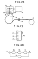
- An example of a conventional apparatus having a die provided with an adjusting mechanism which can adjust thickness of film along the width thereof is now described with reference to Figs. 28 to 30.
- Molten plastic is fed from an extruder 1 b (Fig. 28) to a die 2b.
- the molten plastic is expanded in a manifold 3b in the width direction perpendicular to paper of Fig. 28 showing the die 2b and flows down from a slit-shaped outlet 5b of die lips 4b.
- the molten plastic flowing down from the outlet 5b is cooled by a cooling roller 6b and solidified to be film 7b so that the film is wound on a winder 10b.
- a thickness gauge 11 b measures thickness of the film 7b.
- the thickness gauge 11 b utilizes radiation due to the natural disintegration of radioactive substance to measure thickness of the film 7b in accordance with degree of reduction of the radiation intensity when the radiation passes through the film 7b.
- the thickness gauge includes a single detection element which is moved in the reciprocating manner along the N idth of the film 7b to measure thickness of the film 7b along the width.
- the thickness of the film 7b is maintained to be a predetermined thickness along the width.
- the thickness of the film 7b is not necessarily identical along the width thereof.
- thickness adjusting mechanisms 12b which serve to change a discharge amount of molten plastic along the length of the slot of the die lips 4b are disposed dispersedly along the length of the slot of the die lips 4b.
- the thickness adjusting mechanism 12b there are the following types, for example:
- the thickness of the film 7b can be automatically controlled by adjustment of the thickness adjusting mechanism 12b.
- a multiplicity of heaters 12a are embedded in a die 2a at both sides of a gap 3a and the heaters 12a are distributed along the width so that the speed of molten plastic flowing through the gap 3a is maintained to constant.
- the temperature of the heater 12 which is disposed in a place where the thickness of film is small is increased so that the speed of the molten plastic flowing through the place is increased and the thickness of the film 6a therein is increased to correct the thickness of film.
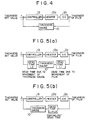
- Fig. 4 is a block diagram of a conventional thickness controller.
- the controller 13 supplies a command to a heater 12a to change a temperature of heat generated by the heater 12a.
- the temperature of the heater 12a is changed, the flowing speed of the molten plastic in the die 2a is changed so that thickness of a portion of the film corresponding to the place where the temperature of the heater is changed can be controlled.
- Fig. 30 is a block diagram of a conventional thickness controller for one operating terminal device of the thickness adjusting mechanism 12b.
- a controller 13b is supplied with a difference between a thickness b of a portion of the film measured by the thickness gauge 11 b and a set value a of thickness.
- the controller 13b calculates an amount of operation for the adjusting mechanism 12b corresponding to the portion of the film measured by the thickness gauge 11 and supplies it to the adjusting mechanism 12b.
- a discharge amount of molten plastic in the die lips 4b is changed and thickness of the portion of the film controlled by the mechanism 12b is changed to effect the thickness control.
- the thickness control over the whole width of the film can be made-by provision of the number of the control loop blocks of Fig. 30 corresponding to the number of places in which the thickness control is performed.
- the conventional film thickness controller as described above has drawbacks as follows:
- the conventional film thickness controller has (A) a first drawback of producing a large dead time and (B) a second drawback of generating the interference effect. Description is now made to problems due drawbacks.
- a film thickness controller for use in an extrusion molding apparatus and a flowing type molding apparatus of film including a die having a mechanism which controls a discharge amount of molten plastic along the width of the film and a thickness gauge for detecting a variation of thickness of the film after the elapse of a dead time L 1 corresponding to a time required for movement of the film between the die and the thickness gauge, comprises a subtracter for producing a difference between a thickness value detected by the thickness gauge in a predetermined position along the width of the film and a set value of thickness in the predetermined position, an integrator for time-integrating the difference of thickness produced by said subtracter, a memory for storing past time sequence data of operation amounts of an operating terminal device during a time equal to a sum of the dead time L 1 and a time L 2 until the thickness gauge reaches an end of the film after detection of thickness in the predetermined position, an operational calculator for producing the past time sequence data of operation amounts of the operating terminal device stored in said memory and an estimated value of a state variable at a time earlier than
- a multiplicity of heaters are disposed along the width of the film to control a temperature of molten plastic which is material of the film, and the thickness gauge detects actual thickness of the film at a position downstream of the flowing film and corresponding to the position of the heater in the width direction of the film.
- a difference between the detected actual thickness and a set thickness is calculated by the subtractor and is time-integrated by the integrator while a correction command is fed back.
- a temperature of the heater is controlled and a temperature of the molten plastic is controlled to adjust the fluidity thereof so that thickness of the film is always maintained within the set value.
- the phase delay due to the dead time is corrected by estimation of the past state corresponding to the dead time by the operational calculator and time-integration during the time corresponding the past state by the state shifter and the state prediction device.
- a film thickness controller for use in an extrusion molding apparatus and a flowing type molding apparatus including a die having a slot along which a plurality of operating terminal devices of a discharge amount adjusting mechanism of molten plastic are disposed and a thickness gauge for detecting variation of thickness after the lapse of a dead time corresponding to a time required for movement of the film between the die and the thickness gauge, comprises a thickness data memory for storing thickness data produced by the thickness gauge, a distributor for receiving an output of said thickness data memory and an arrival end identification signal which is produced by the thickness gauge to identify whether the thickness gauge reaches either of both ends of the film, a plurality of basic control means for receiving an output of said distributor and the arrival end identification signal produced by the thickness gauge, a plurality of command value memories each receiving an output of each of said plurality of basic control means, a superposition adder for receiving an output of each of said command value memories, and an operation value memory for receiving an output of said superposition adder and for supplying an output of said operation value memory to said basic control means.
- the basic control systems can control thickness of the film corresponding to each of the heaters (operating terminal devices) containing in the own systems to a predetermined value and can control thickness over the whole width of the film by combination of the basic control systems.
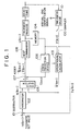
- Fig. 1 is a block diagram of a controller implementing the first invention.
- each of blocks is operated as follows.
- the feedback gain matrix K of the operational calculator of the equation (30) or (34) is obtained for the state equation (27) or (31) of the 39th degree and the output equation (28) of the fifth degree.
- the gain matrix K is obtained as a solution of the optimum regulator problem so that the matrix ⁇ T -(C ⁇ ) T K T ) has a stable eigen value.
- the following values are obtained as eigen values of the matrix ( ⁇ -KC ⁇ ).
- Thickness y 3 is exactly changed to a set value and the change is substantially symmetrical to the thickness y 3 .
- Variation of heat generated by the heater u 3 is largest, variations by the heaters u 2 and u4 are largest next to the heater u 3 , and variations of the heaters u, and u s are smallest.
- the stabilization time is about 18.5 minutes which is considerably large as compared with the stabilization time of 12.4 minutes calculated by the eigen value of the operational calculator (the stabilization time by the eigen value of the regulator is still shorter). This is based on the following reason.
- the command value is defined with weight added as follows.
- Fig. 14 shows a control result when external heat of 8.4 wattage is applied to the heater u 3 .
- Fig. 14(a) shows variations of thickness values y 1 to ys versus time
- Fig. 14(b) shows variations of heat u, to u s generated by the heaters versus time.
- the thickness y 3 is once increased by the external heat of the heater u 3
- the thickness y 3 is returned to the original set value by changing the amounts of heat generated by the heaters u 1 to us and the stabilization time is about 18.5 minutes in the same manner as Fig. 13. It is understood that variation due to the external disturbance is exactly compensated by introducing the integrator in the present control system.
- the thickness values y 2 and y 4 are once increased by influence of external heat through thermal conduction along the width of the die.
- the thickness values y 1 and ys are also influenced similarly, although the influence is small as compared with y 2 and y 4 .
- reduction of heat generated by the heater u 3 is largest
- reduction by the heaters u 2 and u4 is largest next to the heater u 3
- reduction by the heaters u 1 and u s is smallest.
- the process that the same elements as in the first embodiment are utilized, the equations (1) to (19) are derived, the operational calculator for the equations (18) and (19) is designed and the estimated value X(t-L) ⁇ ((t) of X(t-L) is obtained from the detected value of thickness y(t) is quite identical with that of the first embodiment.
- a known ⁇ (t k ) obtained by the calculation performed in the step just before the current step is used to obtain Z (t k+1 ).
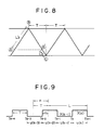
- the calculation is also executed each time the thickness gauge reaches the end B or C of the film as shown in Fig. 8. That is, the calculation is executed at regular intervals of time T.
- the time T is a time required for movement of the thickness gauge along the width of the film.
- Fig. 15 is a diagram for explaining the calculation for the end B for obtaining the estimated value (t k+1 -L B ). It is assumed that the calculation is made at time t k - 2 to t k+1 . Further, it is assumed that the input u(k) of the heater is maintained to constant from t k to t k+1 .
- the time interval T of the calculation is constant, while since the dead times L B and L c for the ends B and C, respectively, are different, the time difference expressing the estimated values ⁇ (t k ) and ⁇ (t k+1 ) is different from the time interval T. Accordingly, the estimated value (t k+1 ) is obtained from the equations (18) and (19) as follows.
- the calculation for the end B shown in Fig. 15 is first considered.
- the equation (49) is expressed by the following equation.
- u(k-1) is a heater input from time t k-1 to t k
- u(k-2) is a heater input from time t k . 2 to t k-1 .
- the equation(50) is expressed by where the discrete value ⁇ (t k ) is expressed by ⁇ (k).
- This integration term I is to predict variation of the state by the input u(t) from time (t-L) to time t.
- the estimated value for the end B is given by
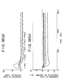
- Fig. 18 shows a control result when external heat of 8W is applied to the heater u 3 stepwise.
- Fig. 18(a) shows variations of thickness values y 1 to y s versus time
- Fig. 18(b) shows variations of amounts u 1 to us of heat generated by the heaters versus time.
- the thickness y 3 is once increased by the external heat, although the thickness y 3 is returned to the original set value by changing the amounts of heat generated by the heaters u 1 to us.
- heat generated by the heaters is repeatedly changed in the steady state and the thickness is also slightly changed repeatedly.
- the equation of the estimated can be used in common for the ends B and C.
- Fig. 19 shows a simulation result when the equations (66), (67) an (68) are used as the equation of the estimated value with the same condition as in Fig. 18. Variation in the steady state of heat generated by the heater is eliminated.
- Fig. 1 is a block diagram of a controller implementing the first invention.
- each of blocks is operated as follows.
- the dead time L due to movement of the film and times Li and L2 required for movement of the thickness gauge from the thickness control point 3 to the film end assume the following values.
- the control calculation execution period T assumes the following value.
- G(s) constituted of g 1 (s), g 2 (s) and g 3 (s) of the equations (69) to (71) can be expressed by an equation of the 77th degree, while the controllable and observable equation has been found to be an equation of the 29th degree. Accordingly, the equations (2) and (3) of the 29th degree are obtained from G(s).
- Fig. 20 shows an example of simulation result obtained by calculation using the gain matrices F, K B and K c obtained above.
- Fig. 20(a) shows variations (variations of detected values of the thickness gauge ) of five thickness values y 1 to ys versus time when the set value of thickness y 3 is changed stepwise by 5 micron.
- Fig. 20(b) shows variations of amounts u 1 to us of heat generated by the heaters in the same condition as Fig. 13(a).
- Thickness y 3 is exactly changed to a set value and the change is substantially symmetrical to the thickness y 3 .
- Variation of heat generated by the heater u 3 is largest, variations by the heaters u 1 and us are largest next to the heater us, and variations of the heaters U2 and u 4 are smallest. This reason is because interference of the heaters u 2 and u 4 to thickness y a is reduced.
- the stabilization time which is estimated by the eigen value determined by the gain matrices F, K B and K c and is 12 minutes is supported by Fig. 20. There is no variation in heat generated by the heater at the steady state, since the equation (66) is employed to compensate the dead time instead of the equation (64) and (65).
- Fig. 21 shows a control result when external heat of 8 watts is applied to the heater us.
- Fig. 21 (a) shows variations of thickness values y 1 to ys versus time
- Fig. 21 (b) shows variations of heat u 1 to us generated by the heaters versus time.
- the thickness y 3 is once increased by the external heat of the heater u 3
- the thickness y 3 is returned to the original set value by changing the amounts of heat generated by the heaters u, to us and the stabilization time is about 12 minutes in the same manner as Fig. 20. It is understood that variation due to the external disturbance is exactly compensated by introducing the integrator in the present control system.
- the thickness values y 2 and y4 are once increased by influence of external heat through thermal conduction along the width of the die.
- the thickness values y 1 and y s are also influenced similarly, although the influence is small as compared with y 2 and y 4 .
- reduction of heat generated by the heater u 3 is largest
- reduction by the heaters u 1 and u s is largest next to the heater u 3
- reduction by the heaters U2 and u 4 is smallest. This is because the reduction in the heaters u 2 and u 4 does not influence thickness ys so much.
- the present invention is configured as described above and accordingly has the following effects.
- the integrator which time-integrates a difference between a detected value of thickness of film at a predetermined position and a set value of thickness is introduced and an output of the integrator is fed back to compensate an amount of heat generated by the heater for external heat influencing thickness of the film so that thickness of the film can be always identical with the set value.
- the state estimated value at time t-L earlier than the current time t by the dead time L is obtained by the operational calculator and the state estimated value at time t-L is time-integrated by the state shifter and the state prediction device during the dead time L so that the state estimated value at the current time t can be obtained to remove deterioration of control performance due to the dead time.
- the first embodiment of the second invention is described with Figs. 22 to 27. In order to avoid duplication, detailed description for the same configuration as a conventional apparatus is omitted.
- Fig. 22 is a block diagram of a film thickness controller for controlling heater and corresponding to a conventional adjusting mechanism 12b (Fig. 28).
- An output of a thickness gauge 11 is connected to a thickness data memory 110.
- a plurality of outputs of the distributor 111 are connected to their corresponding basic control systems 112-i, respectively.
- Each of outputs of the basic control system 112-i is connected to each of their corresponding command memories 113-i for heat generated by the heaters.
- Each of outputs of the command memories 113-i is connected to superposition adder 114.
- An output of the adder 114 is connected to an operation value memory 115.
- An output of the memory 115 is connected back to the basic control systems 112-i.
- Operation of one operating terminal device of the adjusting mechanism for die lips changes thickness of a portion of film corresponding to an adjacent operating terminal device thereto.
- the basic control system including operating terminal devices disposed around a certain operating terminal device and disposed corresponding to portions of film of which thickness is changed by operation of the certain operating terminal device.
- the basic control system can control only thickness of a portion of film corresponding to the operating terminal device selected as a center to a predetermined value of thickness. More particularly, the basic control system can maintain the thickness of a portion of film corresponding to the certain operating terminal device to the predetermined value of thickness by varying operation values of not only the certain operating terminal device but also adjacent operating terminal devices.
- the basic control system takes small number of the operating terminal devices and interference to thickness of film between operating terminal devices into consideration.
- a control system having small number of operating terminal devices and having the following merits is hereinafter referred to as a basic control system.
- the above basic control system is applied to each of operating terminal devices of the adjusting mechanism.
- the stability of thickness control of the whole film is ensured as follows.
- the basic control system can stably control thickness of a portion of film corresponding to the operating terminal device i to which the basic control system i is applied to compensate external disturbance even if external disturbance is added to the operating terminal device in the basic control system. Accordingly, thickness of a portion of film corresponding to the operating terminal device i can be controlled stably even if another basic control system is applied to the operating terminal device i +1.
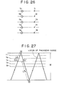
- the thickness gauge measures thickness of film while being moved in reciprocating manner along the width of film. Since the film is moved at a certain speed, the thickness gauge measures thickness of film along a locus as shown in Fig. 27. If a position of a portion of film having thickness t3 is indicated by a point ⁇ in Fig. 27. the dead time L 2 due to movement of the thickness gauge in the case where calculation is made at an end @ of film is expressed by a time L 2 ' of movement of the thickness gauge between the points @ and ⁇ ] in Fig. 27.
- the dead time L 2 due to movement of the thickness gauge is expressed by a time L2" of movement of the thickness gauge between the points (C' and B in Fig. 27.
- the control system for controlling thickness t3 to a predetermined value is characterized in that the dead time L is different depending on whether the calculation is made at the end A or B. Accordingly, the thickness gauge produces an arrival end identification signal for identifying whether the thickness gauge reaches the end A or B.
- a basic control system is considered and this basic control system has five heaters h1 to h5 as operating terminal devices which are controlled by the basic control system, the five heaters being disposed in a longitudinal direction of a slot formed between the die lips.
- the basic control system 112-i can control thickness of a portion of film corresponding to a central heater h3 to a predetermined value even if external disturbance is added to the heaters h1 to h5.
- control object for designing the basic control system is expressed by the transfer function matrix G(s) of the following equation (1 b): where U 1 (s) to Us(s) are Laplace transformed values of heat U 1 (t) to Us(t) generated by the heaters h1 to h5, Y 1 (s) to Y 5 (s) are Laplace transformed values of thicknesses y i (t) to y s (t) of portions corresponding to the heaters h1 to h5, and g 1 (s) to ga(s) are transfer functions corresponding to respective inputs and outputs.
- g 1 (s) is a transfer function which produces temporal variation of thickness t3 when only the heater t3 is changed.
- non-diagonal terms express mutual interference to thickness between heaters.
- the basic control system as a solution of the state equation is the control system described in detail in the first embodiment of the first invention.
- the basic control system satisfies the following conditions.
- the basic control system satisfying the above conditions can be realized by the control system having the configuration shown in Fig. 24.
- the thickness gauge detects thickness while being moved in reciprocating manner along the width of film.
- the gauge reaches the end A or B of film, measurement of thickness of film along the width thereof is completed.
- the calculation is performed and accordingly the execution period T of the calculation is substantially equal to a time required for movement of the thickness gauge along the width and is considered to be constant.
- the basic control system is a discrete time control system.
- the final command value us for the heater h5 is given by the following equation from the above basic control systems (1) to (5).
- the command value of heat generated by one heater h5 is defined by application of five basic control systems.
- the basic control system (3) which controls thickness ys of a portion of film corresponding to the heater us to a predetermined value is taken as an example. Since the command value of heat generated by the heater h(3) is given by an averaged addition value (U 3 (3) +U 3 (1) +u 3 (2) x1/3 of the command values ua 3 ), u 3 (1) and u 3 (2) of the basic control systems (3), (1) and (2), respectively, it is considered that the heater h3 is influenced by a kind of external heat of (u 3 (1) +u 3 (2) x1/3.
- the command value of heat generated by the heater h4 is given by an averaged addition value (u 4 (3) +u 4 (1) +u 4 (2) +u 4 (4) x1/4 of the command values u 4 (3) , u 4(1) , u 4 (2) and u 4 (4) of the basic control systems (3), (1), (2) and (4), respectively, it is considered that the heater h4 is influenced by external heat of (u 4 (1) +u 4 (2) +u 4 (4) x1/4.
- the command value of heat generated by the heater h5 is given by an averaged addition value (u 5 (3) +U 5 (1) +u 5 (2) +u 5 (4)- +u 5 (5) x1/5 of the command values u 5 (3) , u 5 (1) , u 5 (2) , u 5 (4) , u 5 (5) of the basic control systems (3), (1), (2), (4) and (5), respectively, it is considered that the heater h5 is influenced by external heat of (u 5 (1) +u 5 (2) +u 5 (4) - +u 5 (5) x1/5.
- the command value of heat generated by the heater h6 is considered to be influenced by external heat having an averaged addition value (u 6 (3) +u 6 (2) + u 6 (4) +u 6 (5) x1/4 of the command values u 6 (3) , u 6(2) , u 6 (4) and u 6 (5) of the basic control systems (3), (2), (4) and (5), respectively.
- the command value of heat generated by the heater h7 is given by an averaged addition value (u 7 (3) +u 7 (4) +u 7 (5) x1/3 of the command values u 7 (3) , u 7(4) and u 7 (5) of the basic control systems (3), (4) and (5), respectively, it is considered that the heater h7 is influenced by external heat of (u 7 (4) +u 7 (5) x1/3.
- the thickness gauge 11 Since the thickness gauge 11 is moved in reciprocating manner along the width of film to detect thickness of film, thickness data over the width of film is obtained each time the thickness gauge reaches the end of film. The thickness data over the width of film is supplied to the thickness data memory 110.
- the distributor 111 When the distributor 111 is supplied with the arrival end identification signal from the thickness gauge 11 b, the distributor 111 reads out a set of thickness data necessary for the basic control systems 112-i from the thickness data memory 110 and supplies the set of thickness data to the predetermined basic control systems 112-i. Accordingly, the set of thickness data is simultaneously distributed to to the basic control systems which control thickness of portions of film corresponding to the heaters in synchronism with the arrival end identification signal.
- the basic control systems 112-i is supplied with the set of thickness data from the distributor 111 and data of the operation value memory and identifies the end of film which the thickness gauge has reached on the basis of the arrival end identification signal to select the correct dead time L and execute calculation so that a predetermined number of command values of heat are stored in the command value memories 113-2 to 113-N.
- the superposition adder 114 adds outputs of the command value memories 113-1 to 113-N for each heater and calculates an average value thereof to define a final command value S of heat for each heater.
- the basic control systems can control thickness of portions of film corresponding to the heaters to a predetermined value over the width of film stably.
- the feedback gain matrix of the operational calculator which estimates the state before time t k+1 for calculation execution by the dead time L is obtained for the state equation of the 39th degree and the output equation of the fifth degree.
- the gain matrix K is obtained as a solution of the optimum regulator problem using a proper estimation function.
- the following values are obtained as eigen values of the operational calculator for the obtained gain matrix.
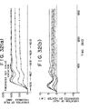
- Figs. 31 and 32 show an example of simulation result obtained by calculation using the state feedback and the gain of the operational calculation obtained above.
- Figs. 31 and 32 show variations of thickness and variation of heat generated by the heaters when the set values of thickness y 3 to ys are changed stepwise by 0.02mm.
- Fig. 31 (a) shows variations of five amounts yi to y 5 of thickness (variation of the detected value of the thickness gauge) versus time.
- Fig. 31-(b) shows variations of heat ui to us generated by the heaters at this time in the same manner as Fig. 31-(a).
- Fig. 32(a) shows variations of thickness ys to y 10 and Fig. 32(b) shows variations of heat u 5 to u 10 generated by the heater.
- variation of the detected thickness value is detected after the lapse of the dead time L after the amount of heat generated by the heater has been changed after the lapse of 16.5 seconds from the change of the set value.
- the heaters h1, h2, h9 and h10 are introduced in consideration of mutual interference to thicknesses y 3 and ys and the thicknesses yi, y 2 , y 9 and y 10 corresponding to the heaters h1, h2, h9 and h10 are not controlled to the set value.
- variations of heat generated by the heaters u 3 and us at the end in the thickness control region are largest.
- variations by the heaters u4 to U7 located in the center are largest next to the heaters u 3 and us, and variations of the heaters u 1 , u 2 , us and u 10 located outside of the control region are smallest.
- the stabilization time is about 18.5 minutes which is considerably large as compared with the stabilization time of 12.4 minutes calculated by the eigen value of the operational calculator (the stabilization time by the eigen value of the regulator is still shorter). This is based on the following reason.
- the command value is defined with weight added as follows.
- W weight coefficient
- Figs. 33 and 34 shows a control result when external heat of 8.4 wattage is applied to the heater u 3 to us.
- Fig. 33(a) shows variations of thickness values y 1 to ys versus time
- Fig. 33(b) shows variations of heat u 1 to u 5 generated by the heaters versus time.
- Fig. 34(a) shows variations of thickness values y 6 to y 10 versus time
- Fig. 34(b) shows variations of heat u 6 to u 1 o generated by the heaters versus time. As seen in Figs.
- the thickness values y 3 to ys are once increased by the external heat of the heater u 3 to us, the thickness values ys to ys are returned to the original set value by changing the amounts of heat generated by the heaters u 1 to u 10 and the stabilization time is about 18.5 minutes in the same manner as Figs. 31 and 33. It is understood that variation due to the external disturbance is exactly compensated by introducing the integrator in the present control system.
- the thickness values y 1 , y 2 , y s and y 10 are once increased by influence of external heat through thermal conduction along the width of the die.
- the first embodiment of the second invention employs the control systems of the first embodiment of the first invention as the basic control systems, while the second embodiment of the second invention employs the control systems of the second embodiment of the first invention as basic control systems.
- the thickness gauge measures thickness of film along a locus as shown in Fig. 27. If a position of thickness t 3 is indicated by the point ⁇ in Fig. 27, the dead time L 2 due to movement of the thickness gauge in the case where calculation is made at the end A of film is expressed by a time L 2 ' corresponding to movement between the points C and A of Fig. 27.
- the dead time L 2 due to movement of the thickness gauge is expressed by a time L 2 " corresponding to movement between the points ⁇ ' and B in Fig. 27.
- the control system which controls thickness t 3 to a predetermined value is characterized in that the dead time 1 of the equation (3b) is different depending on whether calculation is made at the end A or B of film. That is:
- the thickness gauge produces an arrival end identification signal for identifying the end A or B which the thickness gauge has reached.
- the thickness gauge is moved in reciprocating manner along the width of film as shown in Fig. 27 to detect thickness of film and finishes measurement of thickness over the width of film when the thickness gauge has reached the end A or B of film.
- the calculation is executed and accordingly the execution period of calculation is substantially equal to a time required for movement of the thickness gauge over the width of film and the period is considered to be constant.
- the basic control system is a discrete time control system.
- the state equations (2b) and (3b) are controllable and observable.
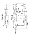
- the relation of the input u(t) and the output y(t) is shown in Fig. 23 from the equations (2b) and (3b).
- Double line in Fig. 23 indicates vector value.
- a configuration of the basic control system of the second embodiment is also the same as that of Fig. 24.
- Double line of Fig. 24 indicates vector value.
- the configuration of the basic control system shown in Fig. 24 is as follows:
- the state estimated value at time t k+1 is not continuous for each calculation and changes stepwise.
- the state estimated value at the end A is larger than the state estimated value at the end B and the operation value of the heater defined by multiplying the state estimated value by the feedback gain is also repeatedly varied unevenly. There is a drawback that variation of the operation value is maintained even in the steady state.
- the first embodiment of the second invention is identical with the second embodiment thereof with the exception that only the basic control systems are different. Combination of the basic control systems is the same. Accordingly, description for thickness control by the combined basic control systems in the first embodiment of the second invention can be all applied to the second embodiment. That is, description in B1 (h) to (j) is all applied to B2.
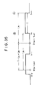
- Fig. 35 is a diagram illustrating the discrete time used to transforms the state equation (2b) to the discrete equation in order to obtain the gain matrix of the operational calculation. In Fig. 35, it is assumed that the estimated value X(t k -L B ) of the state variable at the past time by the dead time L B has been already obtained in the calculation at the end B performed at time t k .
- a proper evaluation function is employed to obtain the gain matrix of the operational calculation as a solution of an optimum regulator problem.
- the following values are obtained as main values for determining convergence of the operational calculation as eigen values of the operational calculator for the obtained gain matrix.
- the estimated error can be reduced with lapse of time. Since the eigen value having the slowest attenuation is 0.7743, the time To Required for attenuation of the estimated error to an initial 1% can be predicted from (0.7743)18 ⁇ 0.01 as follows. For other thickness control points, the gain matrix of the operational calculation having the stabilization time To of 12 minutes was obtained in the same manner.
- Figs. 36 and 37 show an example of simulation result obtained by calculation using the state feedback and the gain of the operational calculation obtained above.
- Figs. 36 and 37 show variations of thickness and variation of heat generated by the heaters when the set values of thickness y 3 to y s are changed stepwise by 5 micron.
- Fig. 36(a) shows variations of five amounts y 1 to ys of thickness (variation of the detected value of the thickness gauge) versus time.
- Fig. 36-(b) shows variations of heat ui to u s generated by the heaters at this time in the same manner as Fig. 36-(a).
- Fig. 37(a) shows variations of thickness ys to y 10 and Fig. 37(b) shows variations of heat u 6 to u 10 generated by the heater.
- variation of the detected thickness value is detected after the lapse of the dead time L after the amount of heat generated by the heater has been changed after the lapse of 22.5 seconds from the change of the set value.
- the heaters h1, h2, h9 and h10 are introduced in consideration of mutual interference to thicknesses ys and ys and the thicknesses y 1 , y 2 , ys and y 10 corresponding to the heaters h1, h2, h9 and h10 are not controlled to the set value.
- variations of heat generated by the heaters u 3 and u s at the end in the thickness control region are largest, variations by the heaters u 4 to u 7 located in the center are largest next to the heaters u 3 and us, and variations of the heaters ui, U2 , us and u 10 located outside of the control region are smallest.
- thickness is controlled to the predetermined value in about 12 minutes after a set value of thickness has been changed, that is, the stabilization time 12 minutes supports a result estimated from the above mentioned eigen value.
- Figs. 38 and 39 shows a control result when external heat of 8 wattage is applied to the heater us to us.
- Fig. 38(a) shows variations of thickness values y, to y s versus time
- Fig. 38(b) shows variations of heat u 1 to u s generated by the heaters versus time.
- Fig. 39(a) shows variations of thickness values y 6 to y 10 versus time
- Fig. 39(b) shows variations of heat u 6 to u 10 generated by the heaters versus time.
- the thickness values y 3 to y 8 are once increased by the external heat of the heater u 3 to u s
- the thickness values y 3 to y s are returned to the original set value by changing the amounts of heat generated by the heaters u 1 to u 10 and the stabilization time is about 12 minutes in the same manner as Figs. 36 and 37. It is understood that variation due to the external disturbance is exactly compensated by introducing the integrator in the present control system.
- the thickness values y 1 , y 2 , y s and y io are once increased by influence of external heat through thermal conduction along the width of the die.
- the adjusting mechanism for controlling thickness of film includes the die provided with a multiplicity of operating terminal devices disposed along the width of film so that thickness control of a portion of film corresponding to one operating terminal device is effected to compensate external disturbance added to the operating terminal device and its adjacent terminal devices, and there is provided the state prediction function to remove influence due to the dead time for thickness detection so that the basic control systems with good response can be applied to control thickness of film to the predetermined value. Further, the basic control system is applied for each control of thickness of a portion of film corresponding to the operating terminal device so that thickness control over the whole width of film is performed stably.
Landscapes
- Engineering & Computer Science (AREA)
- Mechanical Engineering (AREA)
- Physics & Mathematics (AREA)
- General Physics & Mathematics (AREA)
- Automation & Control Theory (AREA)
- Health & Medical Sciences (AREA)
- Artificial Intelligence (AREA)
- Computer Vision & Pattern Recognition (AREA)
- Evolutionary Computation (AREA)
- Medical Informatics (AREA)
- Software Systems (AREA)
- Extrusion Moulding Of Plastics Or The Like (AREA)
Priority Applications (1)
| Application Number | Priority Date | Filing Date | Title |
|---|---|---|---|
| EP94104089A EP0608918B1 (de) | 1988-02-17 | 1989-02-17 | Steuergerät für die Dicke einer Schicht |
Applications Claiming Priority (8)
| Application Number | Priority Date | Filing Date | Title |
|---|---|---|---|
| JP32784/88 | 1988-02-17 | ||
| JP3278488 | 1988-02-17 | ||
| JP3512388 | 1988-02-19 | ||
| JP35123/88 | 1988-02-19 | ||
| JP300962/88 | 1988-11-30 | ||
| JP300963/88 | 1988-11-30 | ||
| JP63300962A JPH01295821A (ja) | 1988-02-17 | 1988-11-30 | フイルム厚み制御装置 |
| JP63300963A JPH01295822A (ja) | 1988-02-19 | 1988-11-30 | フイルム厚み制御装置 |
Related Child Applications (2)
| Application Number | Title | Priority Date | Filing Date |
|---|---|---|---|
| EP94104089A Division EP0608918B1 (de) | 1988-02-17 | 1989-02-17 | Steuergerät für die Dicke einer Schicht |
| EP94104089.1 Division-Into | 1989-02-17 |
Publications (3)
| Publication Number | Publication Date |
|---|---|
| EP0329157A2 true EP0329157A2 (de) | 1989-08-23 |
| EP0329157A3 EP0329157A3 (en) | 1990-08-29 |
| EP0329157B1 EP0329157B1 (de) | 1995-05-10 |
Family
ID=27459685
Family Applications (2)
| Application Number | Title | Priority Date | Filing Date |
|---|---|---|---|
| EP94104089A Expired - Lifetime EP0608918B1 (de) | 1988-02-17 | 1989-02-17 | Steuergerät für die Dicke einer Schicht |
| EP89102761A Expired - Lifetime EP0329157B1 (de) | 1988-02-17 | 1989-02-17 | Steuergerät für die Dicke einer Schicht |
Family Applications Before (1)
| Application Number | Title | Priority Date | Filing Date |
|---|---|---|---|
| EP94104089A Expired - Lifetime EP0608918B1 (de) | 1988-02-17 | 1989-02-17 | Steuergerät für die Dicke einer Schicht |
Country Status (3)
| Country | Link |
|---|---|
| US (1) | US4994976A (de) |
| EP (2) | EP0608918B1 (de) |
| DE (2) | DE68922510T2 (de) |
Cited By (4)
| Publication number | Priority date | Publication date | Assignee | Title |
|---|---|---|---|---|
| WO1992007701A1 (de) * | 1990-10-25 | 1992-05-14 | Brückner Maschinenbau Gernot Brückner Gmbh & Co. Kg | Verfahren zur herstellung von flächen- und im querschnitt ringförmigen extrudaten sowie vorrichtung zur durchführung des verfahrens |
| EP0521749A1 (de) * | 1991-07-01 | 1993-01-07 | Sollac | Verfahren und Einrichtung zur Regelung einer metallurgischen Behandlung angewandt auf einem vorbeilaufenden Produkt |
| EP0542177A3 (en) * | 1991-11-12 | 1993-09-08 | Mitsubishi Jukogyo Kabushiki Kaisha | Film thickness controller |
| WO2004060637A1 (de) * | 2003-01-06 | 2004-07-22 | Windmöller & Hölscher Kg | Verfahren und vorrichtung zur regelung der dicke extrudierter folie |
Families Citing this family (10)
| Publication number | Priority date | Publication date | Assignee | Title |
|---|---|---|---|---|
| JPH10225973A (ja) * | 1997-02-14 | 1998-08-25 | Toshiba Mach Co Ltd | 熱変位式自動tダイの制御方法 |
| DE60138121D1 (de) * | 2000-09-19 | 2009-05-07 | Toray Industries | Verfahren zur herstellung von folie |
| EP1987942A3 (de) * | 2000-09-21 | 2009-12-23 | Toray Industries Inc. | Durch Extrudieren und Formen eines Rohstoffes erzeugtes Blatt |
| DE10300374B4 (de) * | 2003-01-06 | 2010-12-23 | Windmöller & Hölscher Kg | Verfahren und Vorrichtung zur Regelung der Dicke extrudierter Folie |
| US7160094B2 (en) * | 2003-06-03 | 2007-01-09 | Avery Dennison Corporation | Die assembly |
| WO2012170713A1 (en) * | 2011-06-07 | 2012-12-13 | 3M Innovative Properties Company | Slot die position adjustment |
| DE102015006891A1 (de) * | 2015-06-03 | 2016-09-01 | Reifenhäuser GmbH & Co. KG Maschinenfabrik | Anlage zum Herstellen einer Folienbahn sowie Verfahren zum Betreiben einer solchen Anlage |
| DE18801943T1 (de) * | 2017-05-17 | 2020-06-04 | Everix, Inc. | Ultradünne, flexible dünnschichtfilter mit räumlich oder zeitlich variierenden optischen eigenschaften und herstellungsverfahren dafür |
| CN110722770B (zh) * | 2017-05-28 | 2021-08-13 | 浙江商业职业技术学院 | 一种膜厚测量辅助定位装置 |
| EP4259341B1 (de) * | 2020-12-09 | 2025-07-30 | 3M Innovative Properties Company | Schlitzdüsenpositionseinstellung mit klingeleinschränkung |
Family Cites Families (13)
| Publication number | Priority date | Publication date | Assignee | Title |
|---|---|---|---|---|
| US3557351A (en) * | 1967-04-12 | 1971-01-19 | Industrial Nucleonics Corp | Property measurement signal filtering method and apparatus for eliminating predetermined components |
| JPS537940B2 (de) * | 1973-06-12 | 1978-03-23 | ||
| US4124342A (en) * | 1974-05-31 | 1978-11-07 | Toray Industries, Inc. | Apparatus for controlling the gap between lips of a die for extruding a plastic sheet material |
| DE2548567B2 (de) * | 1975-10-30 | 1977-11-10 | Messerschmitt-Bölkow-Blohm GmbH, 8000 München | Verfahren zur digitalen regelung eines systems mit einem zeitdiskreten beobachterverfahren |
| JPS6059775B2 (ja) * | 1979-07-18 | 1985-12-26 | 松下電器産業株式会社 | アナログ・デジタル変換器 |
| DE3176317D1 (en) * | 1980-02-28 | 1987-08-20 | Mitsubishi Heavy Ind Ltd | Method and apparatus for controlling the thickness of a film product |
| JPS56133135A (en) * | 1980-03-21 | 1981-10-19 | Mitsubishi Heavy Ind Ltd | Controlling method for thickness of film |
| JPS5839050A (ja) * | 1981-09-01 | 1983-03-07 | Nec Corp | 集積回路 |
| JPS5844463A (ja) * | 1981-09-11 | 1983-03-15 | Ricoh Co Ltd | 原稿送り装置付複写機 |
| JPS60132727A (ja) * | 1983-12-22 | 1985-07-15 | Toshiba Mach Co Ltd | プラスチツクフイルム等の厚さ調整方法 |
| US4804556A (en) * | 1984-08-30 | 1989-02-14 | E. I. Du Pont De Nemours And Company | Edge thickness control system |
| US4707779A (en) * | 1984-11-20 | 1987-11-17 | Measurex Corporation | Process for controlling a parameter based upon filtered data |
| US4841208A (en) * | 1986-09-11 | 1989-06-20 | Toshiba Kikai Kabushi Kaisha | Position control system including a quick response control |
-
1989
- 1989-02-15 US US07/311,223 patent/US4994976A/en not_active Expired - Fee Related
- 1989-02-17 EP EP94104089A patent/EP0608918B1/de not_active Expired - Lifetime
- 1989-02-17 DE DE68922510T patent/DE68922510T2/de not_active Expired - Fee Related
- 1989-02-17 DE DE68929083T patent/DE68929083T2/de not_active Expired - Fee Related
- 1989-02-17 EP EP89102761A patent/EP0329157B1/de not_active Expired - Lifetime
Cited By (7)
| Publication number | Priority date | Publication date | Assignee | Title |
|---|---|---|---|---|
| WO1992007701A1 (de) * | 1990-10-25 | 1992-05-14 | Brückner Maschinenbau Gernot Brückner Gmbh & Co. Kg | Verfahren zur herstellung von flächen- und im querschnitt ringförmigen extrudaten sowie vorrichtung zur durchführung des verfahrens |
| US5397514A (en) * | 1990-10-25 | 1995-03-14 | Bruckner Maschinenbau Gernot Bruckner Gmbh & Co. Kg | Process for producing flat and annular-cross-section extrudates and device for implementing the process |
| EP0521749A1 (de) * | 1991-07-01 | 1993-01-07 | Sollac | Verfahren und Einrichtung zur Regelung einer metallurgischen Behandlung angewandt auf einem vorbeilaufenden Produkt |
| FR2678645A1 (fr) * | 1991-07-01 | 1993-01-08 | Lorraine Laminage | Procede de regulation d'un traitement metallurgique effectue sur un produit en defilement et dispositif pour sa mise en óoeuvre. |
| US5370902A (en) * | 1991-07-01 | 1994-12-06 | Sollac | Regulating method for a metallurgical treatment carried out on a moving product and device for its implementation |
| EP0542177A3 (en) * | 1991-11-12 | 1993-09-08 | Mitsubishi Jukogyo Kabushiki Kaisha | Film thickness controller |
| WO2004060637A1 (de) * | 2003-01-06 | 2004-07-22 | Windmöller & Hölscher Kg | Verfahren und vorrichtung zur regelung der dicke extrudierter folie |
Also Published As
| Publication number | Publication date |
|---|---|
| EP0329157A3 (en) | 1990-08-29 |
| DE68929083D1 (de) | 1999-11-11 |
| EP0608918A1 (de) | 1994-08-03 |
| DE68922510T2 (de) | 1995-09-21 |
| EP0329157B1 (de) | 1995-05-10 |
| DE68929083T2 (de) | 2000-05-25 |
| DE68922510D1 (de) | 1995-06-14 |
| EP0608918B1 (de) | 1999-10-06 |
| US4994976A (en) | 1991-02-19 |
Similar Documents
| Publication | Publication Date | Title |
|---|---|---|
| EP0329157A2 (de) | Steuergerät für die Dicke einer Schicht | |
| Lefkowitz | Multilevel approach applied to control system design | |
| US9329582B2 (en) | Method and apparatus for minimizing error in dynamic and steady-state processes for prediction, control, and optimization | |
| Mayne | Differential dynamic programming–a unified approach to the optimization of dynamic systems | |
| KR20000010791A (ko) | 예측, 제어 및 최적화를 위한 동적 및 정상-상태 프로세스를 모델링하는 방법 및 장치 | |
| EP0542177A2 (de) | Steuergerät für die Dicke einer Schicht | |
| JPH03142501A (ja) | 特に流体温度を制御するための適応プロセス制御システム | |
| Alamir et al. | A new formulation of economic model predictive control without terminal constraint | |
| Qu et al. | Globally stabilizing adaptive control design for nonlinearly-parameterized systems | |
| Wang et al. | A differential Lyapunov-based tube MPC approach for continuous-time nonlinear processes | |
| Loeblein et al. | Economic performance analysis in the design of on-line batch optimization systems | |
| US5038397A (en) | Film thickness controller | |
| Murzabekov et al. | The optimal control problem with fixed-end trajectories for a three-sector economic model of a cluster | |
| Grimm et al. | Adjoint estimation from a direct multiple shooting method | |
| RU2211470C2 (ru) | Адаптивная цифровая комбинированная система управления нестационарными технологическими объектами | |
| Fraser-Andrews | A multiple-shooting technique for optimal control | |
| Li et al. | Adaptive interval type-2 fuzzy SOSM control for nonlinear systems with uncertainties | |
| Gogol et al. | Adaptive-robust control of technological processes with delay on control | |
| Colaneri et al. | Stabilization, regulation, and optimization of multirate sampled-data systems | |
| JPH0626841B2 (ja) | 成形品厚み制御装置 | |
| Lin et al. | System identification for state feedback integral observer control of polymer plastic extrusion | |
| JP2662197B2 (ja) | 厚み制御装置 | |
| Michiels | Delays effects in dynamical systems and networks: analysis and control interpretations | |
| Smith | Modified Smith predictor for extruded diameter control | |
| Hughes | Self-tuning and adaptive control-a reviewofsomebasictechniques |
Legal Events
| Date | Code | Title | Description |
|---|---|---|---|
| PUAI | Public reference made under article 153(3) epc to a published international application that has entered the european phase |
Free format text: ORIGINAL CODE: 0009012 |
|
| AK | Designated contracting states |
Kind code of ref document: A2 Designated state(s): DE FR |
|
| PUAL | Search report despatched |
Free format text: ORIGINAL CODE: 0009013 |
|
| AK | Designated contracting states |
Kind code of ref document: A3 Designated state(s): DE FR |
|
| 17P | Request for examination filed |
Effective date: 19901107 |
|
| 17Q | First examination report despatched |
Effective date: 19930319 |
|
| GRAA | (expected) grant |
Free format text: ORIGINAL CODE: 0009210 |
|
| AK | Designated contracting states |
Kind code of ref document: B1 Designated state(s): DE FR |
|
| XX | Miscellaneous (additional remarks) |
Free format text: TEILANMELDUNG 94104089.1 EINGEREICHT AM 17/02/89. |
|
| REF | Corresponds to: |
Ref document number: 68922510 Country of ref document: DE Date of ref document: 19950614 |
|
| ET | Fr: translation filed | ||
| PLBE | No opposition filed within time limit |
Free format text: ORIGINAL CODE: 0009261 |
|
| STAA | Information on the status of an ep patent application or granted ep patent |
Free format text: STATUS: NO OPPOSITION FILED WITHIN TIME LIMIT |
|
| 26N | No opposition filed | ||
| PGFP | Annual fee paid to national office [announced via postgrant information from national office to epo] |
Ref country code: DE Payment date: 20010212 Year of fee payment: 13 |
|
| PGFP | Annual fee paid to national office [announced via postgrant information from national office to epo] |
Ref country code: FR Payment date: 20010213 Year of fee payment: 13 |
|
| PG25 | Lapsed in a contracting state [announced via postgrant information from national office to epo] |
Ref country code: DE Free format text: LAPSE BECAUSE OF NON-PAYMENT OF DUE FEES Effective date: 20020903 |
|
| PG25 | Lapsed in a contracting state [announced via postgrant information from national office to epo] |
Ref country code: FR Free format text: LAPSE BECAUSE OF NON-PAYMENT OF DUE FEES Effective date: 20021031 |
|
| REG | Reference to a national code |
Ref country code: FR Ref legal event code: ST |