EP0329240A2 - Procédé pour déterminer la distribution spectrale de la magnétisation nucléaire dans un volume limité et dispositif pour la mise en oeuvre du procédé - Google Patents
Procédé pour déterminer la distribution spectrale de la magnétisation nucléaire dans un volume limité et dispositif pour la mise en oeuvre du procédé Download PDFInfo
- Publication number
- EP0329240A2 EP0329240A2 EP89200333A EP89200333A EP0329240A2 EP 0329240 A2 EP0329240 A2 EP 0329240A2 EP 89200333 A EP89200333 A EP 89200333A EP 89200333 A EP89200333 A EP 89200333A EP 0329240 A2 EP0329240 A2 EP 0329240A2
- Authority
- EP
- European Patent Office
- Prior art keywords
- frequency
- frequency pulse
- sequence
- sequences
- pulse
- Prior art date
- Legal status (The legal status is an assumption and is not a legal conclusion. Google has not performed a legal analysis and makes no representation as to the accuracy of the status listed.)
- Withdrawn
Links
- 230000005415 magnetization Effects 0.000 title claims abstract description 36
- 238000000034 method Methods 0.000 title claims abstract description 23
- 230000003595 spectral effect Effects 0.000 title abstract description 8
- 238000005481 NMR spectroscopy Methods 0.000 claims description 12
- 230000009466 transformation Effects 0.000 claims description 10
- 238000010168 coupling process Methods 0.000 claims description 4
- 238000005859 coupling reaction Methods 0.000 claims description 4
- 230000008878 coupling Effects 0.000 claims description 3
- 238000001228 spectrum Methods 0.000 abstract description 9
- 230000001351 cycling effect Effects 0.000 abstract description 7
- 230000010363 phase shift Effects 0.000 description 6
- 239000000126 substance Substances 0.000 description 4
- XLYOFNOQVPJJNP-UHFFFAOYSA-N water Substances O XLYOFNOQVPJJNP-UHFFFAOYSA-N 0.000 description 4
- 239000002207 metabolite Substances 0.000 description 3
- 230000010355 oscillation Effects 0.000 description 3
- 230000002123 temporal effect Effects 0.000 description 3
- 238000012935 Averaging Methods 0.000 description 2
- 230000008901 benefit Effects 0.000 description 2
- 230000008033 biological extinction Effects 0.000 description 2
- 238000010586 diagram Methods 0.000 description 2
- 230000005284 excitation Effects 0.000 description 2
- 230000006698 induction Effects 0.000 description 2
- 108091081062 Repeated sequence (DNA) Proteins 0.000 description 1
- 230000004913 activation Effects 0.000 description 1
- 210000004556 brain Anatomy 0.000 description 1
- 230000008859 change Effects 0.000 description 1
- 238000001514 detection method Methods 0.000 description 1
- 230000000694 effects Effects 0.000 description 1
- 125000004435 hydrogen atom Chemical group [H]* 0.000 description 1
- 230000002452 interceptive effect Effects 0.000 description 1
- 230000008569 process Effects 0.000 description 1
Images

Classifications
-
- G—PHYSICS
- G01—MEASURING; TESTING
- G01R—MEASURING ELECTRIC VARIABLES; MEASURING MAGNETIC VARIABLES
- G01R33/00—Arrangements or instruments for measuring magnetic variables
- G01R33/20—Arrangements or instruments for measuring magnetic variables involving magnetic resonance
- G01R33/44—Arrangements or instruments for measuring magnetic variables involving magnetic resonance using nuclear magnetic resonance [NMR]
- G01R33/48—NMR imaging systems
- G01R33/4818—MR characterised by data acquisition along a specific k-space trajectory or by the temporal order of k-space coverage, e.g. centric or segmented coverage of k-space
- G01R33/482—MR characterised by data acquisition along a specific k-space trajectory or by the temporal order of k-space coverage, e.g. centric or segmented coverage of k-space using a Cartesian trajectory
-
- G—PHYSICS
- G01—MEASURING; TESTING
- G01R—MEASURING ELECTRIC VARIABLES; MEASURING MAGNETIC VARIABLES
- G01R33/00—Arrangements or instruments for measuring magnetic variables
- G01R33/20—Arrangements or instruments for measuring magnetic variables involving magnetic resonance
- G01R33/44—Arrangements or instruments for measuring magnetic variables involving magnetic resonance using nuclear magnetic resonance [NMR]
- G01R33/48—NMR imaging systems
- G01R33/54—Signal processing systems, e.g. using pulse sequences ; Generation or control of pulse sequences; Operator console
- G01R33/56—Image enhancement or correction, e.g. subtraction or averaging techniques, e.g. improvement of signal-to-noise ratio and resolution
-
- G—PHYSICS
- G01—MEASURING; TESTING
- G01R—MEASURING ELECTRIC VARIABLES; MEASURING MAGNETIC VARIABLES
- G01R33/00—Arrangements or instruments for measuring magnetic variables
- G01R33/20—Arrangements or instruments for measuring magnetic variables involving magnetic resonance
- G01R33/44—Arrangements or instruments for measuring magnetic variables involving magnetic resonance using nuclear magnetic resonance [NMR]
- G01R33/48—NMR imaging systems
- G01R33/483—NMR imaging systems with selection of signals or spectra from particular regions of the volume, e.g. in vivo spectroscopy
- G01R33/4838—NMR imaging systems with selection of signals or spectra from particular regions of the volume, e.g. in vivo spectroscopy using spatially selective suppression or saturation of MR signals
Definitions
- the invention relates to a method for determining the nuclear magnetization distribution in a limited volume range with several sequences, wherein in each sequence in the presence of a stationary homogeneous magnetic field, three high-frequency pulses act on an examination area, of which the first and the second interact with one of two magnetic fields, the two of which Gradients run perpendicular to one another, and the stimulated echo signals generated in each sequence are subjected to an addition and a Fourier transformation, and an arrangement for carrying out the method.
- Such a method is known from EP-OS 87 200 261.
- a certain disadvantage of this method is that the third of the three high-frequency pulses is also a so-called slice-selective pulse, which is generated in connection with a magnetic gradient field, and that after this pulse and shortly before the reception of the stimulated echo signal, a magnetic gradient field is again present. and is turned off.
- the magnetic gradient fields during and after the radio frequency pulse generate eddy currents which are effective longer than the magnetic gradient fields which generate them. These eddy currents in turn result in magnetic fields which have a disruptive effect on the phase of the stimulated echo signal.
- each sequence comprises a partial sequence preceding the three high-frequency pulses, by means of which the nuclear magnetization is dephased everywhere outside a layer which runs parallel to the plane defined by the directions of the two gradient directions, and in that the sequence is administered in sequence sequences , wherein in each sequence sequence the sequences are repeated n times, where n is greater than or equal to 3, that all sequences of a sequence sequence differ from one another in the phase difference between the first and the second high-frequency pulse by 360 ° / n or an integer multiple other than zero differ from this and that the nuclear magnetic resonance signals generated by the sequences are added to one another in such a way that the FID signals generated by the third high-frequency pulse compensate each other.
- the partial sequence dephases the nuclear magnetization in the examination area everywhere outside of a certain layer.
- the first two high-frequency pulses after the partial sequence tilt the nuclear magnetization in the intersection of the layer mentioned and two layers perpendicular thereto in the direction of the homogeneous stationary magnetic field or antiparallel to it.
- the third high-frequency pulse therefore generates a stimulated echo signal in this cutting area. Since no magnetic gradient field is switched on and off during and after this third high-frequency pulse, this stimulated echo signal remains largely unaffected by eddy currents.
- a single, possibly identically repeated sequence of this type cannot, however, stimulate the nuclear magnetization of all substances in the examination area.
- the third high-frequency pulse generates interfering FID signals in the layer outside the cutting area.
- phase cycling which is defined in more detail in the claim, allows all frequency components in the volume range determined by the magnetic gradient fields to be detected and the unwanted FID signals which come from parts of the layer outside this volume range to be suppressed.
- a further development of the invention provides that the phase of the third high-frequency pulse of each sequence within a sequence sequence differs by 360 ° / n or an integer multiple of this value from the phase of this high-frequency pulse in the other sequences.
- the nuclear spin examination apparatus shown schematically in FIG. 1 contains an arrangement consisting of four coils 1 for generating a homogeneous stationary magnetic field, which can be in the order of a few tenths to a few T. This field runs in the z direction of a Cartesian coordinate system.
- the coils 1 arranged concentrically to the z-axis can be arranged on a spherical surface 2.
- the patient 20 to be examined is located inside these coils.
- each coil 3 is preferably arranged on the same spherical surface. Furthermore, four coils 7 are provided, which generate a magnetic gradient field Gx (i.e. a magnetic field, the strength of which changes linearly in one direction) which also runs in the z direction, but whose gradient runs in the x direction.
- Gx i.e. a magnetic field, the strength of which changes linearly in one direction
- a magnetic gradient field Gy running in the z-direction with a gradient in the y-direction is generated by four coils 5, which can be identical to the coils 7, but which are arranged spatially offset from one another by 90 °. Only two of these four coils are shown in FIG. 1.
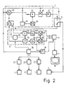
- a high-frequency modulated current is supplied to the high-frequency coil from a high-frequency generator during each high-frequency pulse. - Following three high-frequency pulses, the high-frequency coil 11 serves to receive the stimulated echo signal generated in the examination area. Instead, however, a separate high-frequency receiving coil can also be used.
- the high-frequency coil 11 is connected on the one hand to a high-frequency generator 4 and on the other hand to a high-frequency receiver 6 via a switching device 12.
- the high-frequency generator 4 contains a high-frequency oscillator 40 which is digitally controllable in frequency and which has vibrations with a frequency equal to the Larmor frequency of the atomic nuclei to be excited at the field strength generated by the coils 1.
- the output of the oscillator 40 is connected to an input of a mixer 43.
- the mixer 43 is supplied with a second input signal from a digital-to-analog converter 44, the output of which is connected to a digital memory 45. Controlled by a control device 15, a sequence of digital data words representing an envelope signal is read out of the memory.
- the mixer 43 processes the input signals supplied to it so that the carrier oscillation modulated with the envelope signal appears at its output.
- the output signal of the mixer 43 is fed via a switch 46 controlled by the control device 15 to a high-frequency power amplifier 47, the output of which is connected to the switching device 12. This is also controlled by the control device 15.
- the receiver 6 contains a high-frequency amplifier 60, which is connected to the switching device and to which the stimulated echo signal induced in the high-frequency coil 11 is supplied, the switching device having to have the corresponding switching state.
- the amplifier 60 has a mute input controlled by the control device 15, via which it can be blocked, so that the gain is practically zero.
- the output of the amplifier is connected to the first inputs of two multiplicative mixer stages 61 and 62, which each deliver an output signal corresponding to the product of their input signals.
- a signal with the frequency of the oscillator 40 is fed to the second inputs of the mixer stages 61 and 62, a phase shift of 90 ° between the signals at the two inputs. This phase shift is generated with the aid of a 90 ° phase shifter 48, the output of which is connected to the input of the mixer 62 and the input of which is connected to the input of the mixer 61 and to the output of the oscillator 40.
- the output signals of the mixer 61 and 62 are each fed to an analog-digital converter 65 and 66 via low-pass filters 63 and 64, which suppress the frequency supplied by the oscillator 40 and all frequencies above it and allow low-frequency components to pass through.
- the analog-to-digital converters 65 and 66 and the memory 14 receive their clock pulses from a clock pulse generator 16, which can be blocked or released by the control device 15 by the signal S16 via a control line, so that only one defined by the control device 15 Measuring interval, the signals supplied by the high-frequency coil 11 and transposed into the low-frequency range can be converted into a sequence of digital data words and stored in the memory 14.
- the three coil arrangements 3, 5 and 7 are each supplied with a current by the current generator 23, 25 and 27, the course of which can be controlled by the control unit 15.
- the data words or samples stored in the memory 14 are fed to a computer 17, which uses a discrete Fourier transformation to determine the spectral distribution of the nuclear magnetization and to determine the distribution on a suitable reproduction unit, e.g. a monitor 18.
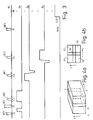
- FIG. 3 shows the time course of various signals received or generated with the circuit according to FIG. 2 for the method according to the invention.
- the first line shows the time course of the output signal of the high-frequency generator 4.
- the second, third and fourth lines show the time course of the magnetic gradient field Gx, Gy or Gz, which is generated by means of the coil arrangement 7, 5 or 3 and the generator 27, 25 or 23 is generated.
- the fifth line shows the time course of the control signal supplied by the control device 15 to the clock pulse generator 16.
- the first high-frequency pulse HF1 ' is a broadband 90 ° high-frequency pulse, the middle of which occurs at time t0.
- the FID signal associated with this high-frequency pulse is switched on by the magnetic gradient field Gx, which is between this high-frequency pulse and the next high-frequency pulse HF2 ', is dephased.
- the second high-frequency pulse HF2 ' is a broadband 180 ° high-frequency pulse that occurs at time t1.
- a narrow-band 90 ° high-frequency pulse HF3 ' occurs at time t2, t2 preferably being chosen such that the 180 ° high-frequency pulse HF2' lies in the middle between the two high-frequency pulses HF1 'and HF3'.
- the magnetic gradient field Gx is switched on again, so that the nuclear magnetization in a layer perpendicular to the x-axis - the layer S - is influenced in a different way than the nuclear magnetization outside the layer; the integral over the magnetic gradient field Gx between the two high-frequency pulses HF1 'and HF2' is equal to the integral over the field Gx after the second high-frequency pulse HF2 until time t2.
- the high-frequency pulse HF1 'excites the entire examination area because it is not slice-selective.
- the associated FID signal ie the signal caused by the free induction decay
- the magnetic gradient field is switched on again after the second high-frequency pulse and is sufficient for the aforementioned integral equation until time t2, a spin-echo signal results in the examination area at time t2.
- the nuclear magnetization is rotated again in the layer S within the examination area by 90 °, so that the nuclear magnetization in this layer then either runs again in the z direction or antiparallel to it.
- the high-frequency pulse HF3 ' is only effective for layer S, the nuclear magnetization outside layer S is excited in the entire examination area at time t2.
- this nuclear magnetization is dephased in that the magnetic gradient field Gx remains switched on beyond time t2.
- This partial sequence is followed by a narrow-band 90 ° high-frequency pulse HF1 (at time t3), which is accompanied by the activation of a magnetic gradient field Gy.
- the time course of the magnetic gradient field Gy is chosen such that the integral over this magnetic gradient field has the value zero from time t3 until this field is switched off.
- the magnetic gradient field Gy is already before the start of the high frequency pulse HF1 switched on.
- the high-frequency pulse HF1 in conjunction with the magnetic gradient field Gy, causes the nuclear magnetization to be excited in a layer perpendicular to the y direction.
- another narrow-band 90 ° high-frequency pulse HF2 follows at time t4.
- the magnetic gradient field Gz is switched on and in such a way that the time integral from the start of the switch-on until the time t4 has the value zero.
- the gradient field remains switched on for a certain time after the time t4, but ends before the next high-frequency pulse HF3. Since no magnetic gradient field is switched on during this high-frequency pulse, it covers the entire examination area.
- This can be a broadband ("hard") 90 ° high-frequency pulse, but also a frequency-selective 90 ° high-frequency pulse.
- this high-frequency pulse is designed in such a way that the nuclear magnetization of protons bound to fat is not excited thereby, the occurrence of fat signals is prevented which can interfere with nuclear magnetic resonance spectroscopy, for example of the brain. If the spectroscopic examination is disturbed by strong signals from protons bound in water, the frequency-selective high-frequency pulse HF3 must be designed in such a way that its spectrum does not contain the frequency required for the excitation of water.
- the second high-frequency pulse HF2 influences the nuclear magnetization in a layer perpendicular to the z-axis.
- the third high-frequency pulse HF3, which occurs at time t5, calls in the intersection area Vo (cf. FIG. 4b) of layer S with the high-frequency pulses HF1 and HF2 excited layers as a nuclear magnetic resonance signal a stimulated echo signal.
- this signal is subjected to a discrete Fourier transformation - preferably after averaging over the stimulated echo signals from sequences which are identical to the sequence shown in FIG. 3.
- the stimulated echo signal caused by the sequence shown in FIG. 3 is unsuitable for the determination of the frequency spectrum not only because of the poor signal-to-noise ratio (this could be increased by repetition and by averaging the signals obtained), but above all because because part of the spectral components excited by the first high-frequency pulse is suppressed in this nuclear magnetic resonance signal and because other nuclear magnetic resonance signals also occur which do not depend on the nuclear magnetization in the desired range Vo. This is explained in more detail below:
- the stimulated echo signal from the Vo region is superimposed on FID signals that originate from regions within the layer that lie outside the layers influenced by the high-frequency pulses HF1 and HF2.
- the nuclear magnetization is determined by one of the two 90 ° high-frequency pulses HF1 or HF2 and by the third 90 ° high-frequency pulse HF3.
- the nuclear magnetization either runs in the z direction or perpendicular to it and therefore does not contribute to the nuclear magnetic resonance signal. Outside of these layers, however, excitation occurs only through the third high-frequency pulse HF3, and therefore this third high-frequency pulse generates FID signals in these areas of the layer S overlay the stimulated echo signal from the Vo range.
- 4b which shows a top view of the layer S, shows the position of these regions V1, V2, V3 and V4.
- Phase cycling is understood to mean that a sequence is repeated several times after a certain repetition time, the phase of at least one high-frequency pulse being changed from sequence to sequence.
- the phase of a high-frequency pulse is understood to mean the angle which, in a coordinate system rotating with the center frequency of the high-frequency pulse, the magnetic field component of the relevant high-frequency pulse rotating with the same direction of rotation takes up with respect to the x- (or y-) axis.
- the three high-frequency pulses HF1, HF2 and HF3 have the same phase.
- the phase of the second high-frequency pulse is offset by + 120 ° from the phase of the first high-frequency pulse, while the phase of the third high-frequency pulse is offset from that of the first high-frequency pulse by -120 °.
- the phases of the high-frequency pulses can be shifted, for example, by briefly changing the frequency of the oscillator 40 after the first or second high-frequency pulse until a (temporal) phase shift is achieved which corresponds to the desired (spatial) phase shift , after which the frequency is returned to its original value.
- the oscillation of the oscillator is then offset from the original oscillation by, for example, 120 °, so that the component of the high-frequency magnetic field generated by the coil 11, which also rotates with the rotating coordinate system, also assumes a position offset by 120 ° in this coordinate system.
- the phase of the oscillator 40 is brought back into the original position, for example by temporarily changing the frequency.
- the phases of the third high-frequency pulse in the three sequences are mutually offset by 120 °, the same phase shift also results in the FID signals resulting from this third pulse in the individual sequences. As a result, these signals compensate when added together. Since the phase difference between the first high-frequency pulse and the second high-frequency pulse continues to change by 120 ° from sequence to sequence, In the second and third sequences, those components are also excited by the second high-frequency pulse HF2 whose Larmor frequency is such that there is a phase shift of 90 ° (or an odd integer multiple thereof) in relation to the oscillator frequency in the period between the first and the second high-frequency pulse ) results and which are therefore not excited in the first sequence.
- the sum of the stimulated echo signals resulting from the three sequences results in a sum signal that contains the frequency components of all substances contained in the volume element Vo that can be excited by the high-frequency pulses HF1, HF2 and HF3.
- the frequency spectrum of the range Vo therefore results from the Fourier transformation via this sum signal.
- the sequence sequence consisting of the three sequences is preferably repeated several times, and the resulting components are added and then subjected to a Fourier transformation.
- all three high-frequency pulses HF1..HF3 tilt the nuclear magnetization clockwise around the x-axis, i.e. the co-rotating component of the high-frequency magnetic field runs in the y direction.
- the second radio frequency pulse tilts the nuclear magnetization around the y axis
- the third radio frequency pulse tilts the nuclear magnetization around the -y axis, i.e. the co-rotating component of the high-frequency magnetic field runs in the + x or -x direction.
- the second pulse HF2 in the second sequence excites all the components that are not excited by the second high-frequency pulse in the first sequence, because at the time of this high-frequency pulse they run parallel to the co-rotating component of the magnetic field or antiparallel to it.
- the nuclear magnetization is tilted about the -x-axis by the second and the third high-frequency pulse, while in the first high-frequency pulse the nuclear magnetization is tilted about the x-axis, ie the second and the third high-frequency pulse HF2 and HF3 have opposite the first high-frequency pulse HF1 a phase shifted by 180 °.
- the phase of the second high-frequency pulse in the fourth sequence is around that of the first high-frequency pulse 270 ° (or -90 °) offset, while the phase of the third high-frequency pulse is offset by 90 °.
- the third high-frequency pulse in the first and the second sequence has the opposite phase position as in the third and in the fourth sequence.
- the FID signal components in the nuclear magnetic resonance signals compensate for one another when they are added to one another.
- the second high-frequency pulse in the second sequence influences the signal components which the second high-frequency pulse HF2 in the first sequence cannot influence - and vice versa.
- the second high-frequency pulse in the third and in the fourth sequence influences the summation of the nuclear magnetic resonance signals generated by the four sequences.
- the summation takes place in that the output signals S65 of the A / D converter 65 which occur after the individual sequences are added to one another by adding the data words which represent the nuclear magnetic resonance signal in the same temporal position with respect to the associated sequence to one another.
- phase position of the high-frequency pulses HF1 ', HF2', HF3 'which precede the three high-frequency pulses HF1, HF2 and HF3 can be chosen as desired; so it does not have to be varied.
- phase position of the first high-frequency pulses in the sequence sequence with "x" is in itself arbitrary; it is only important that the phase position of the subsequent pulses HF2 and HF3 differs therefrom in the aforementioned manner.
- the third high-frequency pulse of the third sequence can also have the same phase as the third high-frequency pulse HF3 of the first sequence in the second table.
- ⁇ 180 °
- metabolites In medical diagnostics, the detection of metabolites is often desirable. These generally have a J-coupling with a scalar coupling constant J of, for example, 7 Hz.
- J a scalar coupling constant
- the spectrum of such metabolites depends cosinically on the time interval t4-t3 between the two high-frequency pulses HF2 and HF1, the zero being obtained if this is temporal Distance corresponds to the reciprocal of twice the scalar coupling constant, ie is approximately 70 ms.
- the time interval between the two high-frequency pulses HF1 and HF2 must therefore be as small as possible, for example 10 ms, or it must be twice as long as the time required for extinction, for example around 140 ms.
- a frequency-selective high-frequency pulse can be used instead of the third high-frequency pulse HF3, for example a so-called binomial high-frequency pulse, which is designed in such a way that it cannot excite the nuclear spins of hydrogen protons bound to water.
Landscapes
- Physics & Mathematics (AREA)
- High Energy & Nuclear Physics (AREA)
- Condensed Matter Physics & Semiconductors (AREA)
- General Physics & Mathematics (AREA)
- Health & Medical Sciences (AREA)
- General Health & Medical Sciences (AREA)
- Nuclear Medicine, Radiotherapy & Molecular Imaging (AREA)
- Radiology & Medical Imaging (AREA)
- Engineering & Computer Science (AREA)
- Signal Processing (AREA)
- Magnetic Resonance Imaging Apparatus (AREA)
Applications Claiming Priority (2)
| Application Number | Priority Date | Filing Date | Title |
|---|---|---|---|
| DE3804924 | 1988-02-17 | ||
| DE3804924A DE3804924A1 (de) | 1988-02-17 | 1988-02-17 | Verfahren zur ermittlung der spektralen verteilung der kernmagnetisierung in einem begrenzten volumenbereich und anordnung zur durchfuehrung des verfahrens |
Publications (2)
| Publication Number | Publication Date |
|---|---|
| EP0329240A2 true EP0329240A2 (fr) | 1989-08-23 |
| EP0329240A3 EP0329240A3 (fr) | 1991-01-02 |
Family
ID=6347579
Family Applications (1)
| Application Number | Title | Priority Date | Filing Date |
|---|---|---|---|
| EP19890200333 Withdrawn EP0329240A3 (fr) | 1988-02-17 | 1989-02-13 | Procédé pour déterminer la distribution spectrale de la magnétisation nucléaire dans un volume limité et dispositif pour la mise en oeuvre du procédé |
Country Status (4)
| Country | Link |
|---|---|
| US (1) | US4924183A (fr) |
| EP (1) | EP0329240A3 (fr) |
| JP (1) | JPH025929A (fr) |
| DE (1) | DE3804924A1 (fr) |
Cited By (2)
| Publication number | Priority date | Publication date | Assignee | Title |
|---|---|---|---|---|
| EP0386822A3 (fr) * | 1989-03-04 | 1991-03-13 | Philips Patentverwaltung GmbH | Processus d'investigation par R.M.N. et appareil pour l'utilisation de ce procédé |
| EP0516214A1 (fr) * | 1991-05-27 | 1992-12-02 | Koninklijke Philips Electronics N.V. | Procédé et dispositif à résonance magnétique sélective par rapport au volume |
Families Citing this family (10)
| Publication number | Priority date | Publication date | Assignee | Title |
|---|---|---|---|---|
| JPH01170446A (ja) * | 1987-12-25 | 1989-07-05 | Yokogawa Medical Syst Ltd | 核磁気共鳴画像診断装置の領域制限方法 |
| DE3837317A1 (de) * | 1988-11-03 | 1990-05-10 | Philips Patentverwaltung | Kernresonanzspektroskopieverfahren und anordnung zur durchfuehrung des verfahrens |
| DE3920433A1 (de) * | 1989-06-22 | 1991-01-03 | Philips Patentverwaltung | Kernresonanzabbildungsverfahren |
| DE3938370A1 (de) * | 1989-11-18 | 1991-05-23 | Philips Patentverwaltung | Kernspintomographieverfahren und kernspintomograph zur durchfuehrung des verfahrens |
| GB9217718D0 (en) * | 1992-08-20 | 1992-09-30 | British Tech Group | Method of and apparatus for nmr testing |
| US5467016A (en) * | 1993-04-20 | 1995-11-14 | Siemens Medical Systems, Inc. | Saturation selective spectroscopic imaging |
| US5657758A (en) * | 1994-04-08 | 1997-08-19 | The United States Of America As Represented By The Secretary, Department Of Health And Human Services | Method and system for multidimensional localization and for rapid magnetic resonance spectroscopic imaging |
| US5709208A (en) * | 1994-04-08 | 1998-01-20 | The United States Of America As Represented By The Department Of Health And Human Services | Method and system for multidimensional localization and for rapid magnetic resonance spectroscopic imaging |
| JP4739943B2 (ja) * | 2005-12-26 | 2011-08-03 | ジーイー・メディカル・システムズ・グローバル・テクノロジー・カンパニー・エルエルシー | Rfパルス印加方法およびmri装置 |
| DE102016202240A1 (de) * | 2016-02-15 | 2017-08-17 | Siemens Healthcare Gmbh | Magnetresonanz-bildgebung |
Family Cites Families (6)
| Publication number | Priority date | Publication date | Assignee | Title |
|---|---|---|---|---|
| DE3209264A1 (de) * | 1982-03-13 | 1983-09-22 | Bruker Medizintechnik Gmbh, 7512 Rheinstetten | Verfahren zum messen der magnetischen kernresonanz fuer die nmr-tomographie |
| US4521732A (en) * | 1982-03-16 | 1985-06-04 | Pegg David T | Pulse sequence for use in performing nuclear magnetic resonance spectroscopy |
| DE3445689A1 (de) * | 1984-12-14 | 1986-06-19 | Max-Planck-Gesellschaft zur Förderung der Wissenschaften e.V., 3400 Göttingen | Verfahren und einrichtung zur ortsaufgeloesten untersuchung einer probe mittels magnetischer resonanz von spinmomenten |
| DE3543854A1 (de) * | 1985-12-12 | 1987-06-19 | Philips Patentverwaltung | Kernspintomographieverfahren und anordnung zur durchfuehrung des verfahrens |
| US4843549A (en) * | 1986-02-21 | 1989-06-27 | U.S. Philips Corporation | Method of determining the spectral distribution of the nuclear magnetization in a limited volume, and device for performing the method |
| US4843321A (en) * | 1988-04-15 | 1989-06-27 | General Electric Company | Method for volume localized spectral editing of NMR signals produced by metabolites containing coupled spins |
-
1988
- 1988-02-17 DE DE3804924A patent/DE3804924A1/de not_active Withdrawn
-
1989
- 1989-02-10 US US07/309,465 patent/US4924183A/en not_active Expired - Fee Related
- 1989-02-13 EP EP19890200333 patent/EP0329240A3/fr not_active Withdrawn
- 1989-02-14 JP JP1034885A patent/JPH025929A/ja active Pending
Cited By (2)
| Publication number | Priority date | Publication date | Assignee | Title |
|---|---|---|---|---|
| EP0386822A3 (fr) * | 1989-03-04 | 1991-03-13 | Philips Patentverwaltung GmbH | Processus d'investigation par R.M.N. et appareil pour l'utilisation de ce procédé |
| EP0516214A1 (fr) * | 1991-05-27 | 1992-12-02 | Koninklijke Philips Electronics N.V. | Procédé et dispositif à résonance magnétique sélective par rapport au volume |
Also Published As
| Publication number | Publication date |
|---|---|
| US4924183A (en) | 1990-05-08 |
| DE3804924A1 (de) | 1989-08-31 |
| EP0329240A3 (fr) | 1991-01-02 |
| JPH025929A (ja) | 1990-01-10 |
Similar Documents
| Publication | Publication Date | Title |
|---|---|---|
| EP0226247A2 (fr) | Procédé de tomographie à spin nucléaire et dispositif de mise en oeuvre de ce procédé | |
| EP0329240A2 (fr) | Procédé pour déterminer la distribution spectrale de la magnétisation nucléaire dans un volume limité et dispositif pour la mise en oeuvre du procédé | |
| DE3920433A1 (de) | Kernresonanzabbildungsverfahren | |
| EP0412602B1 (fr) | Procédé de spectroscopie RMN et dispositif pour sa mise en oeuvre | |
| EP0357100A2 (fr) | Procédé tomographique à résonance nucléaire et tomographe à résonance nucléaire pour la mise en oeuvre de ce procédé | |
| DE3739856A1 (de) | Kernresonanz-spektroskopieverfahren | |
| EP0259935A2 (fr) | Procédé de tomographie en spins nucléaires et tomographe en spins nucléaires pour la mise en oeuvre du procédé | |
| DE3937428A1 (de) | Kernspintomographieverfahren zur erzeugung getrennter fett- und wasserbilder und anordnung zur durchfuehrung des verfahrens | |
| EP0233675B1 (fr) | Procédé pour déterminer la distribution spectrale de la magnétisation nucléaire dans un volume limité et dispositif pour la mise en oeuvre du procédé | |
| EP0261743B1 (fr) | Procédé pour déterminer la distribution spectrale de la magnétisation nucléaire dans un volume limité | |
| DE3906978A1 (de) | Verfahren zur lokalisierten kernresonanzspektroskopie und anordnung zur durchfuehrung des verfahrens | |
| EP0496447B1 (fr) | Procédé de spectroscopie RMN et dispositif de mise en oeuvre du procédé | |
| EP0232945A2 (fr) | Procédé pour déterminer la distribution de la magnétisation nucléaire dans une couche de région d'examen et tomographe à spin nucléaire pour la mise en oeuvre du procédé | |
| EP0478030B1 (fr) | Procédé pour la spectroscopie RMN à deux dimensions | |
| EP0248469B1 (fr) | Procédé de tomographie dans des spins nucléaires | |
| DE3701849A1 (de) | Verfahren und vorrichtung fuer die kernspintomographie | |
| EP0237105A2 (fr) | Procédé pour déterminer la distribution spectrale de la magnétisation nucléaire dans un volume limité | |
| EP0302550A2 (fr) | Procédé de spectroscopie RMN | |
| EP0300564A2 (fr) | Procédé d'analyse par résonance magnétique nucléaire | |
| EP0386822A2 (fr) | Processus d'investigation par R.M.N. et appareil pour l'utilisation de ce procédé | |
| DE3605547A1 (de) | Verfahren zur ermittlung der spektralen verteilung der kernmagnetisierung in einem begrenzten volumenbereich und anordnung zur durchfuehrung des verfahrens | |
| EP0467467A2 (fr) | Procédé de spectroscopie par résonance magnétique nucléaire | |
| DE3808281A1 (de) | Verfahren zur bestimmung der kernmagnetisierungsverteilung und anordnung zur durchfuehrung des verfahrens | |
| DE3607341A1 (de) | Verfahren zum bestimmen der spektralen verteilung der kernmagnetisierung in einem begrenzten volumenbereich | |
| DE3824274A1 (de) | Kernspinuntersuchungsverfahren und anordnung zur durchfuehrung des verfahrens |
Legal Events
| Date | Code | Title | Description |
|---|---|---|---|
| PUAI | Public reference made under article 153(3) epc to a published international application that has entered the european phase |
Free format text: ORIGINAL CODE: 0009012 |
|
| AK | Designated contracting states |
Kind code of ref document: A2 Designated state(s): DE FR GB NL |
|
| PUAL | Search report despatched |
Free format text: ORIGINAL CODE: 0009013 |
|
| AK | Designated contracting states |
Kind code of ref document: A3 Designated state(s): DE FR GB NL |
|
| STAA | Information on the status of an ep patent application or granted ep patent |
Free format text: STATUS: THE APPLICATION IS DEEMED TO BE WITHDRAWN |
|
| 18D | Application deemed to be withdrawn |
Effective date: 19910902 |