EP0329393A2 - Verschluss für Flaschen oder dgl. - Google Patents
Verschluss für Flaschen oder dgl. Download PDFInfo
- Publication number
- EP0329393A2 EP0329393A2 EP89301406A EP89301406A EP0329393A2 EP 0329393 A2 EP0329393 A2 EP 0329393A2 EP 89301406 A EP89301406 A EP 89301406A EP 89301406 A EP89301406 A EP 89301406A EP 0329393 A2 EP0329393 A2 EP 0329393A2
- Authority
- EP
- European Patent Office
- Prior art keywords
- cap
- bottle
- retention member
- wall
- member body
- Prior art date
- Legal status (The legal status is an assumption and is not a legal conclusion. Google has not performed a legal analysis and makes no representation as to the accuracy of the status listed.)
- Withdrawn
Links
Images



Classifications
-
- B—PERFORMING OPERATIONS; TRANSPORTING
- B65—CONVEYING; PACKING; STORING; HANDLING THIN OR FILAMENTARY MATERIAL
- B65D—CONTAINERS FOR STORAGE OR TRANSPORT OF ARTICLES OR MATERIALS, e.g. BAGS, BARRELS, BOTTLES, BOXES, CANS, CARTONS, CRATES, DRUMS, JARS, TANKS, HOPPERS, FORWARDING CONTAINERS; ACCESSORIES, CLOSURES, OR FITTINGS THEREFOR; PACKAGING ELEMENTS; PACKAGES
- B65D47/00—Closures with filling and discharging, or with discharging, devices
- B65D47/04—Closures with discharging devices other than pumps
- B65D47/20—Closures with discharging devices other than pumps comprising hand-operated members for controlling discharge
- B65D47/26—Closures with discharging devices other than pumps comprising hand-operated members for controlling discharge with slide valves, i.e. valves that open and close a passageway by sliding over a port, e.g. formed with slidable spouts
- B65D47/261—Closures with discharging devices other than pumps comprising hand-operated members for controlling discharge with slide valves, i.e. valves that open and close a passageway by sliding over a port, e.g. formed with slidable spouts having a rotational or helicoidal movement
- B65D47/263—Closures with discharging devices other than pumps comprising hand-operated members for controlling discharge with slide valves, i.e. valves that open and close a passageway by sliding over a port, e.g. formed with slidable spouts having a rotational or helicoidal movement between tubular parts
Definitions
- This invention relates to a cap for bottles or similar containers in liquid, semi-liquid, or viscous form.
- liquid, semi-liquid or relatively viscous liquids such as edible oils, salad dressing preparations, shampoos, lotions, etc.
- liquid, semi-liquid or relatively viscous liquids such as edible oils, salad dressing preparations, shampoos, lotions, etc.
- the containers or bottles which contain these products are provided with threaded caps or caps that were put on the containers with a non-refillable or inviolable caps (as in the case of oils).
- a disadvantage of this type of caps is that, when the user needs to remove the cap from the container, it has been placed too tight around the neck of the container, and its removal is very difficult to the user.
- this invention refers to a cap for bottles and the like that can supply products inside containers, having only two components, which can be molded in only a injection machine.
- the cap of the present invention it is not necessary to remove the cap of the bottle in order to extract the container's contents. This is due to the fact that by merely turning one of its components, the desired amount of the product can be removed from the container.
- the cap includes a detachable ring which is broken when first used. It would guarantee that the product would reach the consumer with the same quality under which the contents were filled within the bottles, and thus prevent that the products from coming altered during the handling provided between the manufacturer and the consumer. Similarly, if the consumer wants to close the container, he only needs to turn the cap with an opposite movement in order to return it to its original position.
- the vacuum action is prevented in the inside of the container because the cap has at least two exit orifices, one of which is used for the product to leave and the other to permit the entry of air into the container.
- It is an object of this invention is to provide an integral cap for bottles and the like, which is manufactured in two pieces, with its components being mechanically attached with a lesser number of manufacturing stages and machines.
- Another object of the present invention is to provide an integral cap for bottles and the like which prevents the removal of the cap from the bottles because it provides a cap with an integral pouring orifice which is opened by first rotating the cap wit an upward movement. This permits the bottled product to come out of the bottle and if is moved in the opposite direction, it seals the bottle.
- Still another object of the invention in preferred forms, is to provide an integral cap for bottles or the like, which contain liquid, semi-liquid or viscous products, that prevents the formation of a vacuum effect because it has at least two orifices, one for letting the product out and the other permitting air to enter the container.
- the present invention provides a cap for a bottle, comprising a retention member to couple hermetically to the mouth of the bottle and a cover engageable with the retention member with means to inhibit separation of the cover from the retention member, wherein the retention member is generally tubular with internal formations to engage the mouth portion of a bottle to inhibit removal therefrom and rotation relative thereto, the cover is axially displacable relative to the retention member and includes at least one orifice for dispensing from the bottle, operable by such axial displacement.
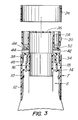
- cap for bottles and the like includes in combination: a retention member body T, of plastic material, having a tubular form.
- the retention member body T having on its lower part, several fastening ribs 10, which lock against the neck or crown of the bottle in order to prevent its slipping upwards, and several internal holding vertical legs 12, which can be attached to the edge of the neck of the bottle E, so it will not turn around the bottle.
- the body T includes internally about of its middle part, an annular seating wall 14 which seats on the mouth of the bottle E; a second annular wall 16, perpendicular to said seating wall 14, to cover, through its lower internal part, the internal part of the neck of the bottle and, on its upper part, it serves as guide for the cover "C", as will be described later; and, a third wall 18 located between the annular wall 16 and the internal wall of the retention member body T, from the annular seating wall 14.
- the third wall 18 having formed a threaded section 20 or a series of grooves (not shown) on its internal part.
- the upper part of the retention member body T comprising, an annular binding edge 22, located on its internal part, and a detachable ring 24 which guarantees the inviolability of the cap.
- a second element of the cap comprises a cover C, also of plastic material, which is constituted by an upper wall 26; an internal tubular wall 28; a second tubular external wall 30; and an annular wall (32) for joint the walls 28 and 30, on its lower end.
- a third tubular wall 34 located perpendicularly below the annular wall 32, having a threaded section 36 or a series of longitudinal borders (now shown) on its outer edge; and a fourth tubular wall 38 located below of the annular wall 32 which has a interlocking outside edge 40.
- cap C shows two orifices 42 and 44 for letting the bottled product out and the second one in letting air into the bottle.
- the orifices 42 and 44 cross transversely, the annular wall 32, showing, on its outer edge, a small conic cavity 46, where a small tubular section 48 surpass.
- the cover C is inserted into the upper part of retention member body T.
- the attachment between both components is carried out between the threaded section 20 of the annular wall 18 and the threaded section 36 of the annular wall 34.
- the integral cap is assembed to the neck of the bottle E, inserting the lower end of the body T around the neck of the bottle. So the locking ribs 10 are slightly bend from body T, and they remain locked in the neck of the container E. The vertical holding legs 12 will stop the turning of the body T around the neck of the bottle.
- cover C When it is desired to use the cap to extract the content of the bottle will be able to move cover C with a first upwards rotational movement, breaking at that moment, the detachable ring 24 of body T. At the time cover C is lifted, orifices 42 and 44 remain free, permitting the extraction of the product kept in the bottle E. Later, once the user has obtained the amount needed, he turns cover C in the opposite direction, and orifices 42 and 44 will be covered by the internal wall of body T. Also the cover C can also have an upward or downward movement for extracting the product. This is due to the coupling of the grooves and edges formed in the body of T and cover C.
Landscapes
- Engineering & Computer Science (AREA)
- Mechanical Engineering (AREA)
- Closures For Containers (AREA)
Applications Claiming Priority (2)
| Application Number | Priority Date | Filing Date | Title |
|---|---|---|---|
| MX010411A MX168418B (es) | 1988-02-15 | 1988-02-15 | Tapon integral de suministro |
| MX10411 | 1988-02-15 |
Publications (2)
| Publication Number | Publication Date |
|---|---|
| EP0329393A2 true EP0329393A2 (de) | 1989-08-23 |
| EP0329393A3 EP0329393A3 (de) | 1990-07-04 |
Family
ID=19741904
Family Applications (1)
| Application Number | Title | Priority Date | Filing Date |
|---|---|---|---|
| EP89301406A Withdrawn EP0329393A3 (de) | 1988-02-15 | 1989-02-15 | Verschluss für Flaschen oder dgl. |
Country Status (5)
| Country | Link |
|---|---|
| US (1) | US4930688A (de) |
| EP (1) | EP0329393A3 (de) |
| BR (1) | BR8900656A (de) |
| CA (1) | CA1299143C (de) |
| MX (1) | MX168418B (de) |
Families Citing this family (19)
| Publication number | Priority date | Publication date | Assignee | Title |
|---|---|---|---|---|
| US5850944A (en) * | 1992-11-19 | 1998-12-22 | Edward S. Robbins, III | Measuring cap with pivoting dispenser |
| US5632417A (en) * | 1992-11-19 | 1997-05-27 | Edward S. Robbins, III | Dispensing cap and related hinge |
| US5547109A (en) * | 1992-11-19 | 1996-08-20 | Robbins, Iii; Edward S. | Container and measuring/dispensing cap assembly |
| US5465871A (en) * | 1992-11-19 | 1995-11-14 | Robbins, Iii; Edward S. | Spice jar and associated dispenser cap |
| US5487494A (en) * | 1992-11-19 | 1996-01-30 | Robbins, Iii; Edward S. | Dispensing cap with internal measuring chamber and selectively useable sifter |
| US5411186A (en) * | 1992-11-19 | 1995-05-02 | Robbins, Iii; Edward S. | Dispensing cap with rotatable top |
| US5542579A (en) * | 1992-11-19 | 1996-08-06 | Robbins, Iii; Edward S. | Dispensing cap with internal measuring chamber and selectively useable sifter |
| US5509579A (en) * | 1992-11-19 | 1996-04-23 | Robbins, Iii; Edward S. | No drip dispensing cap |
| US5791528A (en) * | 1993-09-08 | 1998-08-11 | Edward S. Robbins, III | Clear plastic measuring/dispensing spout for a box-like container |
| USD371297S (en) | 1994-12-06 | 1996-07-02 | Robbins Iii Edward S | Clear plastic measuring/dispensing spout |
| USD378273S (en) * | 1995-08-08 | 1997-03-04 | Edward S. Robbins, III | Dispensing cap |
| USD379148S (en) * | 1995-08-08 | 1997-05-13 | Edward S. Robbins, III | Dispensing cap |
| US5671875A (en) * | 1996-07-02 | 1997-09-30 | Edward S. Robbins, III | Measuring/dispensing closure flip-top cap and built in shut-off blade |
| USD379434S (en) * | 1996-04-10 | 1997-05-27 | Edward S. Robbins, III | Dispensing cap |
| US5799839A (en) * | 1997-03-04 | 1998-09-01 | Megatrade International, Inc. | Dual spout stopper |
| US5850950A (en) * | 1997-05-09 | 1998-12-22 | Magenta Corporation | Container for dispensing powdered granular or flaked substances |
| US5894965A (en) * | 1997-07-29 | 1999-04-20 | Edward S. Robbins, III | Measuring dispensing cap with spring biased flip top |
| FR2815610B1 (fr) * | 2000-10-23 | 2003-02-14 | Valois Sa | Dispositif de fixation et distributeur utilisant un tel dispositif de fixation |
| EP2700588B1 (de) * | 2012-08-21 | 2015-04-01 | Aptar France SAS | Spenderverschluss mit Belüftungsventil |
Family Cites Families (12)
| Publication number | Priority date | Publication date | Assignee | Title |
|---|---|---|---|---|
| US2052798A (en) * | 1936-03-10 | 1936-09-01 | Renicke Herman | Collapsible tube closure |
| FR855975A (fr) * | 1938-06-09 | 1940-05-24 | Dispositif pour la fermeture de tubes cylindriques | |
| GB749975A (en) * | 1954-08-12 | 1956-06-06 | Werner Stoffregen | Improvements in or relating to tube closures |
| US3317093A (en) * | 1964-12-24 | 1967-05-02 | James G Moran | Sealable pouring cap |
| US3471066A (en) * | 1968-01-08 | 1969-10-07 | Leeds & Micallef | Squeeze bottle and dispensing cap therefor |
| BR7108103D0 (pt) * | 1971-12-07 | 1973-04-26 | Brasil Ind Termica | Sistema para fechamento hermetico de garrafas termicas e similares |
| US4480769A (en) * | 1982-06-14 | 1984-11-06 | Antonio Tellini | Re-usable controlled outflow and liquid-tight plug for _bottles and the like |
| US4544063A (en) * | 1984-10-05 | 1985-10-01 | Neward Lance M | Closure for receptacle |
| EP0187567B1 (de) * | 1984-12-07 | 1989-08-02 | Simone Morel | Vorrichtung zum Verschliessen von Tuben, Flaschen usw., die durch Drehen geöffnet oder verschlossen werden |
| US4779774A (en) * | 1986-11-17 | 1988-10-25 | Simone Morel | Telescopic capsule for tubes or flasks |
| BE905791A (fr) * | 1986-11-19 | 1987-03-16 | Lynes Holding Sa | Bouchon verseur. |
| US4773103A (en) * | 1987-02-06 | 1988-09-27 | Dahlheimer Donald J | Adjustable toilet cleaner dispenser |
-
1988
- 1988-02-15 MX MX010411A patent/MX168418B/es unknown
-
1989
- 1989-02-15 CA CA000591145A patent/CA1299143C/en not_active Expired - Lifetime
- 1989-02-15 BR BR898900656A patent/BR8900656A/pt unknown
- 1989-02-15 EP EP89301406A patent/EP0329393A3/de not_active Withdrawn
- 1989-02-15 US US07/311,465 patent/US4930688A/en not_active Expired - Fee Related
Also Published As
| Publication number | Publication date |
|---|---|
| MX168418B (es) | 1993-04-27 |
| US4930688A (en) | 1990-06-05 |
| EP0329393A3 (de) | 1990-07-04 |
| BR8900656A (pt) | 1989-10-10 |
| CA1299143C (en) | 1992-04-21 |
Similar Documents
| Publication | Publication Date | Title |
|---|---|---|
| EP0329393A2 (de) | Verschluss für Flaschen oder dgl. | |
| US5277303A (en) | Two bottle packaging allowing separate storage and mixing for use of two products, particularly liquids | |
| US5078289A (en) | Container with measuring cup closure | |
| JP3312734B2 (ja) | 内容物を貯蔵し混合するための多重区画分配器 | |
| US5875888A (en) | Device for separately storing two components, for mixing them, and for dispensing the mixture | |
| US5875889A (en) | Device for separately packaging two components, for mixing them together and for dispensing the resulting mixture | |
| AU2007246847B2 (en) | Container closure having means for introducing an additive into the contents of the container | |
| US3703975A (en) | Safety closure | |
| US3318496A (en) | Container closure with axial plug | |
| US5542528A (en) | Bottle for preserving in a separated condition substances to be mixed together before dispensing | |
| MXPA06004751A (es) | Cierre de apertura por torsion que tiene membrana frangible inclinada. | |
| US20040112770A1 (en) | Two-component packaging unit | |
| CA1110581A (en) | Spill and tamper resistant safety closure | |
| HUT71857A (en) | Pouring stopper for container | |
| US3073470A (en) | Insertable, self-locking and non-refillable closure for bottles | |
| US5337931A (en) | Dispenser valve | |
| US4417672A (en) | Dispenser for flowable material | |
| IE54245B1 (en) | Stopper made of a synthetic material, equipped with a tamper-proofing ring | |
| EP0329394A2 (de) | Verschluss für Flaschen oder dgl. | |
| US3407976A (en) | Container with plural pour spouts and frangible closure | |
| US5697533A (en) | Dispensing closure | |
| US6412660B1 (en) | Dispensing nozzle for multi-compartment container | |
| US4706837A (en) | Tamper-resistant package | |
| IT8922829A1 (it) | Serbatoio con bocchettone di collegamento | |
| BG63429B1 (bg) | Контейнер за напитки или други течности със сгъваем накрайник |
Legal Events
| Date | Code | Title | Description |
|---|---|---|---|
| PUAI | Public reference made under article 153(3) epc to a published international application that has entered the european phase |
Free format text: ORIGINAL CODE: 0009012 |
|
| AK | Designated contracting states |
Kind code of ref document: A2 Designated state(s): AT BE CH DE ES FR GB GR IT LI LU NL SE |
|
| PUAL | Search report despatched |
Free format text: ORIGINAL CODE: 0009013 |
|
| RHK1 | Main classification (correction) |
Ipc: B65D 47/26 |
|
| AK | Designated contracting states |
Kind code of ref document: A3 Designated state(s): AT BE CH DE ES FR GB GR IT LI LU NL SE |
|
| STAA | Information on the status of an ep patent application or granted ep patent |
Free format text: STATUS: THE APPLICATION IS DEEMED TO BE WITHDRAWN |
|
| 18D | Application deemed to be withdrawn |
Effective date: 19910105 |