EP0329410A2 - Vakuumschalter - Google Patents
Vakuumschalter Download PDFInfo
- Publication number
- EP0329410A2 EP0329410A2 EP89301436A EP89301436A EP0329410A2 EP 0329410 A2 EP0329410 A2 EP 0329410A2 EP 89301436 A EP89301436 A EP 89301436A EP 89301436 A EP89301436 A EP 89301436A EP 0329410 A2 EP0329410 A2 EP 0329410A2
- Authority
- EP
- European Patent Office
- Prior art keywords
- electrode
- vacuum interrupter
- paths
- current
- main
- Prior art date
- Legal status (The legal status is an assumption and is not a legal conclusion. Google has not performed a legal analysis and makes no representation as to the accuracy of the status listed.)
- Granted
Links
Images

Classifications
-
- H—ELECTRICITY
- H01—ELECTRIC ELEMENTS
- H01H—ELECTRIC SWITCHES; RELAYS; SELECTORS; EMERGENCY PROTECTIVE DEVICES
- H01H33/00—High-tension or heavy-current switches with arc-extinguishing or arc-preventing means
- H01H33/60—Switches wherein the means for extinguishing or preventing the arc do not include separate means for obtaining or increasing flow of arc-extinguishing fluid
- H01H33/66—Vacuum switches
- H01H33/664—Contacts; Arc-extinguishing means, e.g. arcing rings
- H01H33/6642—Contacts; Arc-extinguishing means, e.g. arcing rings having cup-shaped contacts, the cylindrical wall of which being provided with inclined slits to form a coil
Definitions
- a vacuum interrupter for interrupting a large current generally includes a pair of main electrodes disposed in a vacuum vessel so as to be movable relatively towards and away from each other, coil electrodes mounted on the rear surfaces of the main electrodes, and rods extending to the exterior of the vacuum vessel from the rear surfaces of the coil electrodes.
- Current flows from one of the rods to the other through the coil electrodes and main electrodes.
- one of the rods is urged by an actuator for interrupting the current
- one of the main electrodes moves away from the other main electrode, and an arc current is generated to flow across the two main electrodes. This arc current is dispersed into filament-like arc currents by a magnetic field.
- Such a coil electrode is disclosed in, for example, US-A-3946179.
- arms connected at one end to a rod, extend in a radial direction to connect at the other end thereof to one end of respective arcuate sections, and the arcuate sections extend in a circumferential direction to be electrically connected at the other end thereof to a main electrode.
- an arm and an assoicated arcuate section constitute a so-called L-shaped conductive member.
- Four L-shaped conductive members are mounted to the rod, and a clearance is formed between the adjacent ones of the four arcuate sections arranged in a circular pattern. Current flows throught the coil electrode via the route of the rod-arms-arcuate sections to the main electrode.
- the current flows through the four arcuate sections in the same direction, that is, the current flows substantially through an imaginary coil of one turn.
- This one-turn current produces a uniform axial magnetic field which acts to produce diffuse arc current flowing across the main electrodes.
- the clearances present in the known coil electrode play an important role for generation of a uniform axial magnetic field in the arcuate sections.
- the known coil electrode is defective in that the axial magnetic field is weak in the vicinity of the clearances.
- an arc current has such a tendency that it migrates from a low intensity portion towards a high intensity portion of an axial magnetic field. Therefore, the arc current flowing through the portions of the main electrode near the clearances migrates toward the central area of the main electrode where the intensity of the axial magnetic field is high, and concentration of the arc current to the central area of the main electrode having the high field intensity results in localized overheating of the main electrode, thereby degrading the capability of current interruption. Since, also, the entire area of the main electrode cannot be effectively utilized for the current interruption, it becomes necessary to increase the size of the main electrode.
- each electrode assembly comprises a substantially disk-shaped main electrode, a cylindrical coil electrode means electrically connected between the rear surface of each of the main electrodes and the respective rod, the electrode means including a cylindrical body which, at one end adjacent to the main electrode, is annular and surrounds an opening, and which has at least two substantially part helical high resistance paths extending along the body from its open end; and a plurality of electrical connections adjacent to the ends of respective ones of the paths between an end edge surface of the body around the opening and the respective main electrode; the arrangement being such that the cylindrical coil electrode means of the two electrode assemblies are similar and symmetrically arranged so that their electrical connections are opposite to one another and corresponding opposed ones of their part helical high resistance paths are substantially parallel to one another.
- the paths extend to an opening, such as a cup-shaped depression in a base portion, at the other end of the body.
- one-turn current flows throughout current paths separated by the high resistance paths so that a uniform axial magnetic field is applied to the main electrode, and an arc current can be uniformly distributed over the entire surface of the main electrode, thereby providing good current interruption performance of the vacuum interrupter.
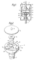
- a vacuum vessel 3 is formed by mounting a pair of end plates 2 one on each end of a cylindrical member 1 of an electrical insulating material.
- a stationary electrode assembly 4 and a movable electrode assembly 5 are disposed opposite to each other in the vacuum vessel 3, and a pair of rods 6 and 7 extend to the exterior of the vacuum vessel 3 from the rear surfaces of respective ones of the electrode assemblies 4 and 5.
- a bellows 8 is mounted between one of the rod 7 and the associated end plate 2. The bellows 8 acts to drive an actuator, not shown, mounted on the rod 7 in its axial direction.
- the movable electrode assembly 5 is electrically moved away from the stationary electrode assembly 4, and an arc current 9 generated between these two electrode assemblies 4 and 5 produces metal vapour.
- the metal vapour attaches to an intermediate shield 1A supported in the insulating cylindrical member 1, and the arc is extinguished by being dispersed by a magnetic field generated in the axial direction of cylindrical coil electrodes 10.
- One of the cylindrical coil electrodes 10 is provided in each of the stationary and movable electrode assemblies 4 and 5.
- the cylindrical coil electrode 10 provided in the movable electrode assembly 5 will be explained with reference to Figure 2.
- the cylindrical coil electrode 10 is essentially identical in both the electrode assemblies 4 and 5.
- the cylindrical coil electrode 10 is mounted to the rear surface of a disk-shaped main electrode which is imperforate, i.e. has a continuous surface from edge to edge.
- the coil electrode 10 includes a cylindrical body 12 having an opening at one end and a closed flat base portion 13, with a central cup-shaped depression 29, at the other end.
- the body 12 is formed in one piece with the rod 7.
- a spacer 14 made of a high resistance material, for example, a stainless steel, is disposed between the main electrode 11 and the bottom 13 of the cylindrical body 12.
- Projections 16 are formed on an annular end edge surface 15 around the opening of the cylindrical body 12, and the main electrode 11 is electrically connected to the projections 16.
- the projections 16 could alternatively be formed on the main electrode.
- Inclined slits 26 are formed at positions of the cylindrical body 12. One end of each of the inclined slits 26 extends from the end surface 15 of the opening of the cylindrical body, adjacent to a projection 16.
- Each inclined slit 26 may be replaced by a stepped slit or by a member of a high resistance material, for example, a stainless steel.
- the requirements is that current flowing from the input end toward the output end of one of the part helical current paths can be separated from current flowing from the input end toward the output end of an adjacent current path, so that current of one turn of an imaginary coil can flow throughout the current paths.
- An electrical coil such as described above is mounted on both main electrical contacts.
- An essential feature of the invention is that opposed portions of the inclined slits 26 are approximately parallel to each other.
- opposed cylindrical coil electrodes 10 are mounted opposed to each other so that projections 16 of opposite electrodes will be directly opposite one another.
- inclined slits 26 for the opposed electrodes will be angularly offset but overlap one another as seen in side elevation ( Figures 3).
- current flowing in one direction for example, from the bottom coil electrode on the left, will flow up, as indicated by arrows, through the projections 16, both main electrodes 11, and through the projections 16 for the top coil electrode.
- an arc current 9 flows across the two electrode assemblies 4 and 5. As shown by the arrows, the arc current 9 flows through the projections 16 and flows then into the rod 7 through the bottom 13 of the cylindrical body 12.
- three projections 16 are provided on the cylindrical body 12.
- provision of more than three projections, for example four, six or more projections can further reduce the overall size of the vacuum interrupter, because current is further dispersed to prevent localized overheating at the projections.
- the intensity of an eddy current generated by a magnetic field produced by current flowing through the bottom 13 of the cylindrical body 12 is limited by the presence of slits 28 which are continuations of the slits 26 into the base portion 13 of the body 12. These base slits 28 are oriented to have a component tangential to the cup-shaped depression in the base portion.
- the resultant magnetic flux is not strong enough to cancel the axial magnet field H. Therefore, an undesirable intensity reduction of the axial magnetic field H can be prevented.
- provision of more slits 28 can further prevent an undesirable reduction of the intensity of the axial magnetic field H.
Landscapes
- High-Tension Arc-Extinguishing Switches Without Spraying Means (AREA)
- Switches With Compound Operations (AREA)
- Switches Operated By Changes In Physical Conditions (AREA)
- Forklifts And Lifting Vehicles (AREA)
- Supplying Of Containers To The Packaging Station (AREA)
- Cookers (AREA)
- Electrophonic Musical Instruments (AREA)
Priority Applications (1)
| Application Number | Priority Date | Filing Date | Title |
|---|---|---|---|
| AT89301436T ATE88296T1 (de) | 1988-02-16 | 1989-02-15 | Vakuumschalter. |
Applications Claiming Priority (2)
| Application Number | Priority Date | Filing Date | Title |
|---|---|---|---|
| US07/156,251 US4839481A (en) | 1988-02-16 | 1988-02-16 | Vacuum interrupter |
| US156251 | 1998-09-18 |
Publications (3)
| Publication Number | Publication Date |
|---|---|
| EP0329410A2 true EP0329410A2 (de) | 1989-08-23 |
| EP0329410A3 EP0329410A3 (en) | 1990-11-07 |
| EP0329410B1 EP0329410B1 (de) | 1993-04-14 |
Family
ID=22558758
Family Applications (1)
| Application Number | Title | Priority Date | Filing Date |
|---|---|---|---|
| EP89301436A Expired - Lifetime EP0329410B1 (de) | 1988-02-16 | 1989-02-15 | Vakuumschalter |
Country Status (7)
| Country | Link |
|---|---|
| US (1) | US4839481A (de) |
| EP (1) | EP0329410B1 (de) |
| JP (1) | JPH027318A (de) |
| KR (1) | KR890013688A (de) |
| AT (1) | ATE88296T1 (de) |
| CA (1) | CA1331204C (de) |
| DE (1) | DE68905942T2 (de) |
Cited By (4)
| Publication number | Priority date | Publication date | Assignee | Title |
|---|---|---|---|---|
| DE4013903A1 (de) * | 1990-04-25 | 1990-11-22 | Slamecka Ernst | Magnetfeld-kontaktanordnung fuer vakuumschalter |
| EP0709867A1 (de) * | 1994-10-31 | 1996-05-01 | Schneider Electric Sa | Elektrischer Vakuumschalter |
| EP0840339A3 (de) * | 1996-11-01 | 1999-01-13 | Eaton Corporation | Vakuumschalter mit Lichtbogenstreuenden Kontakte |
| DE19809828C1 (de) * | 1998-02-27 | 1999-07-08 | Eckehard Dr Ing Gebauer | Vakuumleistungsschalter für Niederspannung |
Families Citing this family (22)
| Publication number | Priority date | Publication date | Assignee | Title |
|---|---|---|---|---|
| US4982059A (en) * | 1990-01-02 | 1991-01-01 | Cooper Industries, Inc. | Axial magnetic field interrupter |
| DE9007343U1 (de) * | 1990-05-11 | 1991-12-19 | Calor-Emag Elektrizitäts AG, 4030 Ratingen | Kontaktanordnung für Vakuumschaltröhren |
| US5387771A (en) * | 1993-04-08 | 1995-02-07 | Joslyn Hi-Voltage Corporation | Axial magnetic field high voltage vacuum interrupter |
| CA2167604A1 (en) * | 1993-07-22 | 1995-02-02 | David Roby | Arc containing device |
| AU681420B2 (en) * | 1993-07-22 | 1997-08-28 | Abb Power Transmission Pty Limited | Arc containing device |
| KR100361390B1 (ko) * | 1994-11-16 | 2003-02-19 | 이턴 코포레이션 | 진공차단기,진공차단기용접점코일조립체및원주전극코일의제조방법 |
| FR2727565B1 (fr) * | 1994-11-29 | 1997-01-17 | Schneider Electric Sa | Interrupteur electrique, notamment sous vide |
| MY119298A (en) * | 1996-09-13 | 2005-04-30 | Cooper Ind Inc | Encapsulated vacuum interrupter and method of making same |
| US6753493B2 (en) * | 2001-06-01 | 2004-06-22 | Hubbell Incorporated | Electrical circuit interrupting device |
| US6965089B2 (en) * | 2003-02-21 | 2005-11-15 | Mcgraw-Edison Company | Axial magnetic field vacuum fault interrupter |
| US6867385B2 (en) * | 2003-02-21 | 2005-03-15 | Mcgraw-Edison Company | Self-fixturing system for a vacuum interrupter |
| US7772515B2 (en) * | 2005-11-14 | 2010-08-10 | Cooper Technologies Company | Vacuum switchgear assembly and system |
| US7488916B2 (en) * | 2005-11-14 | 2009-02-10 | Cooper Technologies Company | Vacuum switchgear assembly, system and method |
| US8450630B2 (en) * | 2007-06-05 | 2013-05-28 | Cooper Technologies Company | Contact backing for a vacuum interrupter |
| US7781694B2 (en) * | 2007-06-05 | 2010-08-24 | Cooper Technologies Company | Vacuum fault interrupter |
| JP5210816B2 (ja) * | 2008-11-14 | 2013-06-12 | 株式会社東芝 | 真空バルブ |
| US20100276395A1 (en) * | 2009-04-29 | 2010-11-04 | Thomas & Betts International, Inc. | 35kV Rubber Molded Fused Vacuum Interrupter |
| CN102754175B (zh) * | 2010-01-18 | 2014-11-05 | 三菱电机株式会社 | 真空阀 |
| CN102642237A (zh) * | 2012-04-28 | 2012-08-22 | 上海板机液压设备有限公司 | 纤维板生产线中热压机闭合与张开速度的控制装置与方法 |
| US9761394B2 (en) | 2013-02-08 | 2017-09-12 | Hubbell Incorporated | Current interrupter for high voltage switches |
| US9640353B2 (en) * | 2014-10-21 | 2017-05-02 | Thomas & Betts International Llc | Axial magnetic field coil for vacuum interrupter |
| EP4128303A4 (de) | 2020-03-31 | 2024-04-17 | Hubbell Incorporated | System und verfahren zum betreiben eines elektrischen schalters |
Family Cites Families (8)
| Publication number | Priority date | Publication date | Assignee | Title |
|---|---|---|---|---|
| DE2527319A1 (de) * | 1974-06-18 | 1976-01-08 | Westinghouse Electric Corp | Vakuum-ausschalter mit kontakten, die ein axiales magnetfeld erzeugen |
| DE3227482A1 (de) * | 1982-07-20 | 1983-02-03 | Ernst Prof. Dr.techn.habil. 1000 Berlin Slamecka | Vakuumschalter-kontaktanordnung mit vorrichtung zur erzeugung eines achsialen magnetfeldes |
| DE3302595A1 (de) * | 1983-01-27 | 1984-08-02 | Calor-Emag Elektrizitäts-Aktiengesellschaft, 4030 Ratingen | Kontaktanordnung fuer vakuumschalter |
| GB8321368D0 (en) * | 1983-08-09 | 1983-09-07 | Vacuum Interrupters Ltd | High current switch contacts |
| DE3334493A1 (de) * | 1983-09-23 | 1985-04-04 | Siemens AG, 1000 Berlin und 8000 München | Kontaktanordnung fuer vakuumschalter |
| US4553003A (en) * | 1984-03-30 | 1985-11-12 | Westinghouse Electric Corp. | Cup type vacuum interrupter contact |
| US4717797A (en) * | 1984-12-18 | 1988-01-05 | Siemens Aktiengesellschaft | Contact arrangement for a vacuum switching tube |
| JPH0731966B2 (ja) * | 1985-07-12 | 1995-04-10 | 株式会社日立製作所 | 真空しや断器 |
-
1988
- 1988-02-16 US US07/156,251 patent/US4839481A/en not_active Expired - Fee Related
-
1989
- 1989-02-15 CA CA000591066A patent/CA1331204C/en not_active Expired - Fee Related
- 1989-02-15 EP EP89301436A patent/EP0329410B1/de not_active Expired - Lifetime
- 1989-02-15 DE DE8989301436T patent/DE68905942T2/de not_active Expired - Fee Related
- 1989-02-15 AT AT89301436T patent/ATE88296T1/de not_active IP Right Cessation
- 1989-02-16 JP JP1037303A patent/JPH027318A/ja active Pending
- 1989-02-16 KR KR1019890001787A patent/KR890013688A/ko not_active Ceased
Cited By (6)
| Publication number | Priority date | Publication date | Assignee | Title |
|---|---|---|---|---|
| DE4013903A1 (de) * | 1990-04-25 | 1990-11-22 | Slamecka Ernst | Magnetfeld-kontaktanordnung fuer vakuumschalter |
| EP0709867A1 (de) * | 1994-10-31 | 1996-05-01 | Schneider Electric Sa | Elektrischer Vakuumschalter |
| US5861597A (en) * | 1994-10-31 | 1999-01-19 | Schneider Electric S.A. | Vacuum electrical switch |
| CN1075663C (zh) * | 1994-10-31 | 2001-11-28 | 施耐德电器工业公司 | 真空开关 |
| EP0840339A3 (de) * | 1996-11-01 | 1999-01-13 | Eaton Corporation | Vakuumschalter mit Lichtbogenstreuenden Kontakte |
| DE19809828C1 (de) * | 1998-02-27 | 1999-07-08 | Eckehard Dr Ing Gebauer | Vakuumleistungsschalter für Niederspannung |
Also Published As
| Publication number | Publication date |
|---|---|
| US4839481A (en) | 1989-06-13 |
| EP0329410B1 (de) | 1993-04-14 |
| DE68905942D1 (de) | 1993-05-19 |
| ATE88296T1 (de) | 1993-04-15 |
| EP0329410A3 (en) | 1990-11-07 |
| JPH027318A (ja) | 1990-01-11 |
| CA1331204C (en) | 1994-08-02 |
| KR890013688A (ko) | 1989-09-25 |
| DE68905942T2 (de) | 1993-07-22 |
Similar Documents
| Publication | Publication Date | Title |
|---|---|---|
| EP0329410B1 (de) | Vakuumschalter | |
| US4704506A (en) | Vacuum interrupter | |
| EP0349303B1 (de) | Vakuumschalter | |
| EP0597434B1 (de) | Vakuumschalter | |
| US4117288A (en) | Vacuum type circuit interrupter with a contact having integral axial magnetic field means | |
| US3946179A (en) | Vacuum interrupter | |
| KR100484076B1 (ko) | 진공단속기용전극조립체,축방향자계단속기용전극코일및진공단속기용전극코일제조방법 | |
| JPH0322007B2 (de) | ||
| US6479779B1 (en) | Vacuum switching device | |
| JPS58145035A (ja) | 真空ア−ク放電装置 | |
| EP0076659A1 (de) | Vakuumschalter | |
| US4345126A (en) | Vacuum interrupter with transfer-type axial magnetic field contacts | |
| JPS6171520A (ja) | 真空開閉器具の接触子装置 | |
| US4695689A (en) | Vacuum circuit breaker | |
| US5726406A (en) | Electrical vacuum switch | |
| US4617434A (en) | Contact arrangement for a vacuum interrupter | |
| JPS58157017A (ja) | しや断器用真空バルブ | |
| EP0264814B1 (de) | Vakuumschalter | |
| JPH02270233A (ja) | 真空バルブ | |
| JPH01315914A (ja) | 真空バルブ | |
| JPH05325739A (ja) | 開閉装置の電極構造 | |
| JPH06150784A (ja) | 真空バルブ | |
| JPH0393120A (ja) | 真空バルブ | |
| JPH04155721A (ja) | 真空バルブ | |
| JPS63170823A (ja) | 真空開閉器 |
Legal Events
| Date | Code | Title | Description |
|---|---|---|---|
| PUAI | Public reference made under article 153(3) epc to a published international application that has entered the european phase |
Free format text: ORIGINAL CODE: 0009012 |
|
| AK | Designated contracting states |
Kind code of ref document: A2 Designated state(s): AT BE CH DE ES FR GB GR IT LI LU NL SE |
|
| PUAL | Search report despatched |
Free format text: ORIGINAL CODE: 0009013 |
|
| AK | Designated contracting states |
Kind code of ref document: A3 Designated state(s): AT BE CH DE ES FR GB GR IT LI LU NL SE |
|
| 17P | Request for examination filed |
Effective date: 19901206 |
|
| 17Q | First examination report despatched |
Effective date: 19910426 |
|
| GRAA | (expected) grant |
Free format text: ORIGINAL CODE: 0009210 |
|
| AK | Designated contracting states |
Kind code of ref document: B1 Designated state(s): AT BE CH DE ES FR GB GR IT LI LU NL SE |
|
| PG25 | Lapsed in a contracting state [announced via postgrant information from national office to epo] |
Ref country code: SE Effective date: 19930414 Ref country code: LI Effective date: 19930414 Ref country code: GR Free format text: LAPSE BECAUSE OF FAILURE TO SUBMIT A TRANSLATION OF THE DESCRIPTION OR TO PAY THE FEE WITHIN THE PRESCRIBED TIME-LIMIT Effective date: 19930414 Ref country code: FR Effective date: 19930414 Ref country code: ES Free format text: THE PATENT HAS BEEN ANNULLED BY A DECISION OF A NATIONAL AUTHORITY Effective date: 19930414 Ref country code: CH Effective date: 19930414 Ref country code: BE Effective date: 19930414 Ref country code: AT Effective date: 19930414 |
|
| REF | Corresponds to: |
Ref document number: 88296 Country of ref document: AT Date of ref document: 19930415 Kind code of ref document: T |
|
| REF | Corresponds to: |
Ref document number: 68905942 Country of ref document: DE Date of ref document: 19930519 |
|
| ITF | It: translation for a ep patent filed | ||
| REG | Reference to a national code |
Ref country code: CH Ref legal event code: PL |
|
| EN | Fr: translation not filed | ||
| PLBE | No opposition filed within time limit |
Free format text: ORIGINAL CODE: 0009261 |
|
| STAA | Information on the status of an ep patent application or granted ep patent |
Free format text: STATUS: NO OPPOSITION FILED WITHIN TIME LIMIT |
|
| PG25 | Lapsed in a contracting state [announced via postgrant information from national office to epo] |
Ref country code: LU Free format text: LAPSE BECAUSE OF NON-PAYMENT OF DUE FEES Effective date: 19940228 |
|
| 26N | No opposition filed | ||
| PGFP | Annual fee paid to national office [announced via postgrant information from national office to epo] |
Ref country code: GB Payment date: 19950110 Year of fee payment: 7 |
|
| PGFP | Annual fee paid to national office [announced via postgrant information from national office to epo] |
Ref country code: DE Payment date: 19950224 Year of fee payment: 7 |
|
| PGFP | Annual fee paid to national office [announced via postgrant information from national office to epo] |
Ref country code: NL Payment date: 19950228 Year of fee payment: 7 |
|
| PG25 | Lapsed in a contracting state [announced via postgrant information from national office to epo] |
Ref country code: GB Effective date: 19960215 |
|
| PG25 | Lapsed in a contracting state [announced via postgrant information from national office to epo] |
Ref country code: NL Effective date: 19960901 |
|
| GBPC | Gb: european patent ceased through non-payment of renewal fee |
Effective date: 19960215 |
|
| NLV4 | Nl: lapsed or anulled due to non-payment of the annual fee |
Effective date: 19960901 |
|
| PG25 | Lapsed in a contracting state [announced via postgrant information from national office to epo] |
Ref country code: DE Effective date: 19961101 |
|
| PG25 | Lapsed in a contracting state [announced via postgrant information from national office to epo] |
Ref country code: IT Free format text: LAPSE BECAUSE OF NON-PAYMENT OF DUE FEES Effective date: 20050215 |