EP0329547A1 - Numerisch angesteuerte elektronische Hochgeschwindigkeitskamera zum Studium von sehr kurzen Vorgängen - Google Patents
Numerisch angesteuerte elektronische Hochgeschwindigkeitskamera zum Studium von sehr kurzen Vorgängen Download PDFInfo
- Publication number
- EP0329547A1 EP0329547A1 EP89400410A EP89400410A EP0329547A1 EP 0329547 A1 EP0329547 A1 EP 0329547A1 EP 89400410 A EP89400410 A EP 89400410A EP 89400410 A EP89400410 A EP 89400410A EP 0329547 A1 EP0329547 A1 EP 0329547A1
- Authority
- EP
- European Patent Office
- Prior art keywords
- electrodes
- digital
- voltage
- pair
- output
- Prior art date
- Legal status (The legal status is an assumption and is not a legal conclusion. Google has not performed a legal analysis and makes no representation as to the accuracy of the status listed.)
- Ceased
Links
- 238000011835 investigation Methods 0.000 title abstract 2
- 230000002123 temporal effect Effects 0.000 claims abstract description 10
- 230000001133 acceleration Effects 0.000 claims abstract description 7
- 238000005259 measurement Methods 0.000 claims description 58
- 230000003287 optical effect Effects 0.000 claims description 23
- 239000013307 optical fiber Substances 0.000 claims description 18
- 238000006243 chemical reaction Methods 0.000 claims description 17
- 230000005693 optoelectronics Effects 0.000 claims description 12
- 230000001276 controlling effect Effects 0.000 claims 1
- 230000001105 regulatory effect Effects 0.000 claims 1
- 238000002474 experimental method Methods 0.000 description 6
- 230000005540 biological transmission Effects 0.000 description 3
- 238000000034 method Methods 0.000 description 3
- 102100027340 Slit homolog 2 protein Human genes 0.000 description 1
- 101710133576 Slit homolog 2 protein Proteins 0.000 description 1
- 230000007423 decrease Effects 0.000 description 1
- 238000010894 electron beam technology Methods 0.000 description 1
Images


Classifications
-
- H—ELECTRICITY
- H01—ELECTRIC ELEMENTS
- H01J—ELECTRIC DISCHARGE TUBES OR DISCHARGE LAMPS
- H01J31/00—Cathode ray tubes; Electron beam tubes
- H01J31/08—Cathode ray tubes; Electron beam tubes having a screen on or from which an image or pattern is formed, picked up, converted, or stored
- H01J31/50—Image-conversion or image-amplification tubes, i.e. having optical, X-ray, or analogous input, and optical output
- H01J31/501—Image-conversion or image-amplification tubes, i.e. having optical, X-ray, or analogous input, and optical output with an electrostatic electron optic system
- H01J31/502—Image-conversion or image-amplification tubes, i.e. having optical, X-ray, or analogous input, and optical output with an electrostatic electron optic system with means to interrupt the beam, e.g. shutter for high speed photography
-
- H—ELECTRICITY
- H01—ELECTRIC ELEMENTS
- H01J—ELECTRIC DISCHARGE TUBES OR DISCHARGE LAMPS
- H01J29/00—Details of cathode-ray tubes or of electron-beam tubes of the types covered by group H01J31/00
- H01J29/98—Circuit arrangements not adapted to a particular application of the tube and not otherwise provided for
Definitions
- the present invention relates to an ultra-fast electronic camera with digital control, for the study of very brief light phenomena.
- This camera can be used to record images with an extremely short exposure time, to make it possible to raise the profile of the evolution, over time, of very brief light phenomena.
- This camera is more particularly applicable to ballistics, detonics, the study of living cells, experiments using lasers, etc.
- the image converter tube with bilamellar optics described in the aforementioned patent, therefore requires for its operation, the use of different electrical sources of high voltages, of fixed or adjustable values.
- the tube successively comprises, along an axis OZ, a flat photocathode 1 perpendicular to this axis, delimited by a narrow slit 2, receiving the photons 3 of the phenomenon studied, and emitting electrons 4.
- This tube also comprises a pair of planar electrodes 5 for extracting and accelerating the electrons, these electrodes being parallel to the slot and to the axis OZ.
- Photocathode 1 is connected to an electrical source 14 DC high voltage power supply, of fixed value (-15,000 volts for example, compared to a reference mass M).
- the electrodes 5 are electron accelerating electrodes; they are connected to the reference mass M.
- the first pair of electrodes 6 of this lens is connected to an electrical source 15 fixed voltage supply (around +400 volts for example).
- the second pair of electrodes 7 of the quadrupole lens is connected to a power source 16 of fixed high voltage power (around -400 volts for example).
- the camera also includes a time focusing lens comprising at least a first, a second and a third pair of electrodes 8, 9A-9B, 10.
- An electrode 9A of the second pair is connected to an adjustable high voltage electrical source 17 (for example between 0 and -10,000 volts).
- An electrode 9B of this second pair is connected to an electrical source 18 of adjustable high voltage (for example between 0 and -10,000 volts).
- This pair of electrodes 9A-9B constitutes a means of deflection of the beam on a screen 11.
- the first and al third pairs of electrodes 8, 10 are connected to the reference ground M.
- the electrodes 9A-9B are deflection electrodes. They are also connected to electrical sources of voltage 19, 20 of fixed values, by a deflection control means 21.
- a screen 11 makes it possible to obtain the image 12 of a slot.
- This camera of known type is also associated with means 13 for recording the image 12 of the slot on the screen 11.
- These recording means can be constituted for example by a photographic plate 13.
- photocathode 1 emits electrons in an area delimited by slot 2, these electrons being produced by the impact of photons 3 on this photocathode. These electrons are accelerated by the pair 5 of acceleration electrodes.
- the electrodes of the first pair 6 of the quadrupole lens make it possible to obtain the image of the slit in the time plane yoz.
- the electrodes of the second pair 7 of this quadrupole lens make it possible to obtain the spatial representation of the slit in a plane xoz parallel to the slit and perpendicular to the photocathode.
- the electrodes 6 of the quadrupole lens make the beam divergent; this is refocused by means of the electrodes 8, 9A, 9B, 10 of the time focusing lens.
- the electrodes 9A-9B provide a temporal deflection of the beam in the yoz plane.
- the known tube used in this camera does not include a time pre-focusing electrode before the quadrupole lens, which decreases the performance of the camera.
- the object of the invention is to remedy these drawbacks and in particular to produce an ultra-fast electronic camera with digital control, for the study of very brief light phenomena in which it is possible, not only to modify the values of the voltages supplied by the adjustable power supplies, but also to measure the values of these tensions, before and during the experiment.
- the camera of the invention makes it possible to carry out these adjustments and these voltage measurements, away from the tube which is often located in a hostile environment and which is not accessible during the experiment.
- this camera uses a tube comprising electrodes of temporal prefocalization making it possible to increase the performances.
- the subject of the invention is an ultra-fast digital camera with digital control, for the study of very brief light phenomena, comprising an image converter tube with bilamellar optics, this tube successively comprising along an oz axis, a planar photocathode perpendicular to this axis, delimited by a narrow slit receiving the photons of the phenomenon studied and emitting electrons, a pair of planar electrodes parallel to said slit and to said axis, electron accelerators, a quadrupole spatial focusing lens comprising a first and a second pair of cylindrical electrodes respectively parallel and perpendicular to said slot and parallel to said axis, a time focusing lens comprising at least first, second and third pairs of electrodes parallel to said slot and to said axis, a screen for forming the image of the slit, the camera further comprising means for recording the image formed on r the screen, adjustable electrical supply sources supplying respectively to outputs, voltages of adjustable values, the outputs of these sources being respectively connected to the
- the remote control station includes control means for supplying coded digital data on outputs. adjustment of voltages, and digital encoded instructions for measurements, a parallel-serial digital conversion means connected to the outputs of the control means, an output of this digital conversion means being connected to a first electrooptical converter supplying, at an output, signals optics corresponding to the coded and multiplexed digital data and instructions, the optical means comprising an emission optical fiber connected by one end to the output of the first electrooptical converter, the adjustment and measurement means comprising a first optoelectronic converter connected by an input to another end of the transmission optical fiber and supplying on an output coded digital data of voltage settings, and coded digital instructions of voltage measurements corresponding to the optical signals received, a digital-analog demultiplexing means having outputs respectively connected to control inputs voltage settings of the adjustable voltage sources, an analog-digital multiplexing means, connected respectively by inputs, to outputs of measurements of the voltage sources, these outputs respectively providing analog signals of voltage measurements, this analog multiplex
- control means of the remote station are connected to a control input of the series-parallel conversion means of this station, to control the selection of one of the measurement means and the control one of the adjustment means.
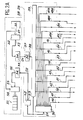
- FIGS. 2A and 2B schematically represent, an ultra-fast digital camera with digital control, in accordance with the invention.
- Figure 1 has already been described to illustrate the state of the art.
- the same elements have the same references in Figure 1 and in Figures 2A AND 2B.
- the camera of the invention shown diagrammatically in FIGS. 2A and 2B, comprises an image converter tube with bilamellar optics, various high voltage power sources and recording means 25, located near this tube.
- the recording means 25 can here be constituted by a CCD type camera (charge transfer camera).
- the camera also comprises, according to the invention, a control station 28, located at a distance from the tube, for controlling, by means 29, adjustments of voltage values supplied by adjustable voltage sources 60, 15, 16, 62 , 63, 64, 65.
- This control station also makes it possible, thanks to the means 29 for controlling adjustments and measurements, to control the measurements of the values of the voltages supplied by the voltage sources.
- the tube represented in this figure is an improvement on the tube of FIG. 1.
- This improvement consists in particular in using a pair of electrodes 22 of temporal prefocusing parallel to the axis OZ and to the slot, located along the axis OZ , between the acceleration electrodes 5 and the electrodes 6, 7 of the quadrupole lens. Thanks to this prefocusing, the camera has a higher light gain without its performance being significantly reduced.
- the tube of this camera also includes a pair of additional shutter electrodes 26, between the pre-focusing electrodes 22 and the electrodes 6, 7 of the quadrupole lens. These additional electrodes 26 are parallel to the slot and to the axis OZ.
- the tube also includes electrodes or deflection plates 73, 74 independent of the time focusing lens, which was not the case in the tube of FIG. 1. These plates are parallel to the slot and are located, along the axis OZ, between a time focusing lens constituted by first, second and third pairs of electrodes 70, 71, 72, and the screen 23.
- the electrodes 70, 71, 72 of the time focusing lens are parallel to the axis OZ and parallel to the slot.
- the voltage sources 14, 61A, 66, 67 of fixed values are respectively connected to the photocathode 1, to a shutter control means 61B itself connected to one of the shutter electrodes 26, and to means 68 of deflection control themselves connected to the deflection plates 73, 74.
- the sources of voltages 60, 15, 16, 62, 63, 64, 65 of adjustable values are respectively connected to the time pre-focusing electrodes 22, to the electrodes 6 , 7 of the quadrupole spatial focusing lens, to the third pair of electrodes 72 of the temporal focusing lens, and to deflection plates 73, 74.
- the acceleration electrodes 5, one of the electrodes of the pair of shutter electrodes 26, the first electrode 70 of the time focusing lens and the screen 23 are connected to a ground of reference M.
- the deflection control means 68, connected to the deflection plates 73, 74 allow the deflection of the electron beam focused on the screen 23.
- the control station 28 is located at a distance from the tube while the means 29 for adjusting and measuring voltages as well as the various sources of voltages are located near the tube.
- a station can moreover control several means 29 for adjustments and measurements associated respectively with several tubes.
- the control station 28 is connected to the adjustment and measurement means 29, by optical means 01, 02 which make it possible, as will be seen in detail below, to transmit voltage adjustment data from the adjustable voltage sources, and measurement instructions by means of voltage measurements; these optical means also make it possible to transmit measurement results to the control station.
- optical means 01, 02 which make it possible, as will be seen in detail below, to transmit voltage adjustment data from the adjustable voltage sources, and measurement instructions by means of voltage measurements; these optical means also make it possible to transmit measurement results to the control station.
- These optical means consist for example of optical fibers.
- the remote control station 28 comprises control means 30 which supply coded digital data on voltage settings on outputs 31 and digital coded instructions for measuring the voltages applied by the sources, to the photocathode, to the electrodes and , by means of the deflection control means 68, to the deflection plates 73, 74.
- These digital control means 30 are constituted for example by a keyboard providing digital data and instructions. They can also be constituted by a microcomputer associated with a library of these data and instructions.
- the station also comprises a parallel-serial converter 32, connected to the outputs of the control means 30.
- This converter with parallel inputs and with serial outputs, provides on an output 33 the data and the instructions, in series.
- This output is connected to an input of a first electro-optical converter 34 which provides on an output 35 optical signals corresponding to the coded digital data and instructions, which it must transmit.
- the optical means comprise a transmitting optical fiber 01, which is connected at one end to the output 35 of the first electro-optical converter 34.
- These optical means also include a second electro-optical converter 52 and a second receiving optical fiber 02 which will be described later in detail.
- the means 29 for adjusting and measuring voltages comprise a first opto-electronic converter 36, which is connected by an input 37, to another end of the transmission optical fiber 01.
- This first opto-electronic converter supplies on an output 38, the coded digital data for voltage settings, and the coded digital instructions for voltage measurements, corresponding to the optical signals received.
- the measurement and adjustment means 29 also comprise a digital-anological demultiplexing means 39 having outputs 80, 81, ..., 86 respectively connected to control voltage adjustment inputs of the adjustable voltage sources 60, 15, 16, 62, 63, 64, 65.
- the demultiplexing means 39 also includes an input connected to an output 51 of an analog-digital multiplexing means 50.
- This multiplexing means 50 is connected respectively by inputs to analog outputs of measurements 40, 41, 42, 43, 44, 45, 46, 47A, 48A, 47B, 48B, respective sources of voltages 14, 60, 61A, 16, 15, 62, 63, 64, 65, 66, 67. It is of course assumed that each source includes a circuit (not shown) providing an analog signal representative of the voltage supplied by this source.
- the output 51 of the analog-digital multiplexing means 50 provides digital values of voltage measurements.
- This output 51 is also connected to the second electrooptical converter 52, which provides on an output 53, optical signals corresponding to the multiplexed digital signals of voltage measurements from different sources.
- the output 51 is also connected, as indicated above, to an input of the digital-analog demultiplexing means 39 which controls the voltage adjustment commands of the adjustable voltage sources.
- the optical fiber for receiving measurements 02 is connected at one end to the output 53 of the second electro-optical converter 52.
- the control station 28 further comprises a second opto-electronic converter 54, connected to another end of the receiving optical fiber 02.
- This second converter 54 supplies on an output, the digital signals multiplexed for measurements of the different voltages.
- a serial-parallel conversion means 55 is connected to the output 56 of the second converter 54.
- the outputs of the conversion means 55 sequentially supply the digital signals for respective measurements of the different voltages applied to the photocathode 1, to the electrodes and to the plates. deflection 73, 74 via the control means 68.
- the outputs of the conversion means 55 are connected to a digital display means 57 of the measured voltages.
- An output of the control means 30 is connected to a control input 58 of the conversion means 55, for selecting any one of the voltages measured by the measurement means.
- the keyboard 30 of the control station 28 allows an operator to select using the keys of this keyboard, the value of the desired voltage and the identification code of the power source 60 as well as the code of identification of the called tube.
- This value and these codes are supplied in digital form by the outputs 31 of the keyboard 30.
- These data and these codes are applied to the converter 32.
- the data and the codes are transmitted in digital form; the first electro-optical converter 34 transforms them into optical signals applied by the optical fiber 01, to the first opto-electronic converter 36.
- the output 38 of this first converter 36 provides these data and these codes, in digital form, to apply them to the digital-analog demultiplexing means 39.
- a corresponding output 80 of the demultiplexing means 39 applies to the control input of the source 60, a corresponding analog adjustment signal at the selected voltage value.
- the keyboard 30 makes it possible to select an identification code or an instruction to control the means for measuring the voltage supplied by the source 60.
- This code is transmitted in digital form to the converter 32, then transformed into optical signals by the first electro converter. -optics 34. These signals are transmitted through the optical fiber 01 to the opto-electronic converter 36, which then transmits by means of demultiplexing 39 a digital instruction corresponding to the selection code of the measurement circuit of the chosen source.
- a corresponding output 41 of this circuit then applies to an input of the analog-digital multiplexing means 50, an analog signal representative of the value of the output voltage of the source 60.
- This analog signal is applied to the analog-digital multiplexing means 50, which provides on an output 51 a digital signal corresponding to the value of the measured voltage.
- This digital signal is transformed into optical signals, thanks to the second electro-optical converter 52. These optical signals are transmitted by the optical fiber 02, to the second opto-electronic converter 54 which provides on its output 56, the digital value of the measured voltage. This numerical value is applied to the series-parallel conversion means 55, the outputs of which are connected to the display means 57.
- the invention makes it possible to achieve the goals mentioned above: the remote control of the values of the voltages applied to the different electrodes of the tube, as well as the voltage measurements provided by the different power supplies.
- This camera is particularly useful when the tube is placed in a hostile environment.
- the use of optical fibers and the transmission of digital signals make it possible to avoid any electrical disturbance in commands or measurements.
- the values of the voltages supplied by the adjustable sources can be modified and measured during the experiment.
- the values of the voltages supplied by the various voltage sources are as follows: Source reference Voltage values 14 -15000 V (fixed) 60 - 6130 V (variable) 61A + 1500 V (impulse) 15 + 182.5 V (variable) 16 - 182.5 V (variable) 62 - 6530 V (variable) 63 - 4775 V (variable) 64 - 200 V (variable) 65 + 200 V (variable) 66 + 1000 V (impulse) 67 - 1000 V (impulse)
Landscapes
- Image-Pickup Tubes, Image-Amplification Tubes, And Storage Tubes (AREA)
- Photometry And Measurement Of Optical Pulse Characteristics (AREA)
Applications Claiming Priority (2)
| Application Number | Priority Date | Filing Date | Title |
|---|---|---|---|
| FR8801867 | 1988-02-17 | ||
| FR8801867A FR2627294B1 (fr) | 1988-02-17 | 1988-02-17 | Camera electronique ultra rapide a commande numerique, pour l'etude de phenomenes lumineux tres brefs |
Publications (1)
| Publication Number | Publication Date |
|---|---|
| EP0329547A1 true EP0329547A1 (de) | 1989-08-23 |
Family
ID=9363336
Family Applications (1)
| Application Number | Title | Priority Date | Filing Date |
|---|---|---|---|
| EP89400410A Ceased EP0329547A1 (de) | 1988-02-17 | 1989-02-14 | Numerisch angesteuerte elektronische Hochgeschwindigkeitskamera zum Studium von sehr kurzen Vorgängen |
Country Status (4)
| Country | Link |
|---|---|
| US (1) | US4945416A (de) |
| EP (1) | EP0329547A1 (de) |
| JP (1) | JPH0210121A (de) |
| FR (1) | FR2627294B1 (de) |
Families Citing this family (4)
| Publication number | Priority date | Publication date | Assignee | Title |
|---|---|---|---|---|
| US5463839A (en) * | 1994-08-04 | 1995-11-07 | The Lakso Company | Apparatus for packaging a predetermined quantity of objects and a counting device therefor |
| EP1197373A2 (de) | 2000-10-10 | 2002-04-17 | Horie Kinzoku Kogyo Kabushiki Kaisha | Mit einem Plastikkraftstofftank verbundene Plastikteile |
| US9451177B2 (en) * | 2013-06-18 | 2016-09-20 | Massachusetts Institute Of Technology | Methods and apparatus for high speed camera |
| JP6401600B2 (ja) * | 2014-12-18 | 2018-10-10 | 浜松ホトニクス株式会社 | ストリーク管及びそれを含むストリーク装置 |
Citations (2)
| Publication number | Priority date | Publication date | Assignee | Title |
|---|---|---|---|---|
| EP0155890A2 (de) * | 1984-03-16 | 1985-09-25 | Commissariat A L'energie Atomique | Bildwandlerröhre mit Spaltenabtastung |
| GB2172991A (en) * | 1985-02-08 | 1986-10-01 | Hamamatsu Photonics Kk | Concurrently measuring a plurality of light signals |
Family Cites Families (8)
| Publication number | Priority date | Publication date | Assignee | Title |
|---|---|---|---|---|
| FR2284978A1 (fr) * | 1974-09-13 | 1976-04-09 | Commissariat Energie Atomique | Tube convertisseur d'images a balayage de fente |
| US4243878A (en) * | 1977-07-07 | 1981-01-06 | Ralph Kalibjian | Ultra-fast framing camera tube |
| US4471378A (en) * | 1979-12-31 | 1984-09-11 | American Sterilizer Company | Light and particle image intensifier |
| US4431914A (en) * | 1981-08-27 | 1984-02-14 | The University Of Rochester | Photoelectron switching in semiconductors in the picosecond time domain |
| JPS61116634A (ja) * | 1984-11-09 | 1986-06-04 | Hamamatsu Photonics Kk | 光フアイバの伝送特性を計測する装置 |
| JPH0762987B2 (ja) * | 1985-04-16 | 1995-07-05 | 浜松ホトニクス株式会社 | 管内に像切出し装置を有するストリ−ク管 |
| US4727427A (en) * | 1986-10-23 | 1988-02-23 | Polaroid Corporation | Electronic imaging camera system with phosphor image receiving and storing device |
| US4837631A (en) * | 1987-09-14 | 1989-06-06 | Peter D. Sahagen | Electronic still camera tube |
-
1988
- 1988-02-17 FR FR8801867A patent/FR2627294B1/fr not_active Expired - Lifetime
-
1989
- 1989-02-14 EP EP89400410A patent/EP0329547A1/de not_active Ceased
- 1989-02-16 JP JP1037293A patent/JPH0210121A/ja active Pending
- 1989-02-17 US US07/312,606 patent/US4945416A/en not_active Expired - Fee Related
Patent Citations (2)
| Publication number | Priority date | Publication date | Assignee | Title |
|---|---|---|---|---|
| EP0155890A2 (de) * | 1984-03-16 | 1985-09-25 | Commissariat A L'energie Atomique | Bildwandlerröhre mit Spaltenabtastung |
| GB2172991A (en) * | 1985-02-08 | 1986-10-01 | Hamamatsu Photonics Kk | Concurrently measuring a plurality of light signals |
Also Published As
| Publication number | Publication date |
|---|---|
| FR2627294A1 (fr) | 1989-08-18 |
| FR2627294B1 (fr) | 1990-06-01 |
| JPH0210121A (ja) | 1990-01-12 |
| US4945416A (en) | 1990-07-31 |
Similar Documents
| Publication | Publication Date | Title |
|---|---|---|
| JP6452202B2 (ja) | 高解像度三次元撮像のシステムおよび方法 | |
| EP3152806A1 (de) | System und verfahren zum induzieren und nachweisen von multiphotonprozessen in einer probe | |
| FR2539525A1 (fr) | Procede pour corriger l'intensite d'un faisceau lors de l'analyse et de l'enregistrement d'une figure | |
| FR2644892A1 (fr) | Appareil de detection de gaz par absorption lumineuse | |
| US7482566B2 (en) | Equalization for a multi-axis imaging system | |
| AU2023341904A1 (en) | Reducing scintillation noise in free space optical communications | |
| WO2016062785A2 (en) | Smart photonic imaging method and apparatus | |
| US7088495B2 (en) | Method and apparatus for time-division multiplexing to improve the performance of multi-channel non-linear optical systems | |
| EP0187091A1 (de) | Transientenanalysesystem | |
| Donaldson et al. | A self-calibrating, multichannel streak camera for inertial confinement fusion applications | |
| EP0187087B1 (de) | Photonenabtasteinrichtung und diese Einrichtung benutzendes Transientenanalysesystem | |
| US5825530A (en) | Arrangement and method for operating and testing an optical device | |
| US5003268A (en) | Optical signal sampling apparatus | |
| US4975717A (en) | Apparatus for recording image | |
| FR2627294A1 (fr) | Camera electronique ultra rapide a commande numerique, pour l'etude de phenomenes lumineux tres brefs | |
| CN112711100A (zh) | 一种电力系统中mems光开关切换路径优化控制装置和方法 | |
| CA2077147C (fr) | Procede et dispositif de commande d'un convertisseur de longueur d'onde optique | |
| EP0015830B1 (de) | Vorrichtung zum Messen des Moduls der Übertragungsfunktion einer optischen Faser und ihre Verwendung | |
| WO2022185020A1 (fr) | Systeme de compensation de la distorsion d'un front d'onde d'un rayonnement lumineux incident | |
| CN111161998B (zh) | 一种激光同轴离子激发装置 | |
| EP0810748B1 (de) | Vorrichtung und Verfahren zum Betreiben und Prüfen einer optischen Vorrichtung | |
| RU2646546C1 (ru) | Способ подстройки коэффициента деления волноводного разветвителя на подложке ниобата лития | |
| JPS61269037A (ja) | 光ファイバの分散特性測定装置 | |
| Yu et al. | 532 nm silicon nitride optical phased array and high-speed calibration and control system | |
| Guy et al. | Optical frequency control for DWDM networks using sum-frequency generation in multilayer waveguides |
Legal Events
| Date | Code | Title | Description |
|---|---|---|---|
| PUAI | Public reference made under article 153(3) epc to a published international application that has entered the european phase |
Free format text: ORIGINAL CODE: 0009012 |
|
| AK | Designated contracting states |
Kind code of ref document: A1 Designated state(s): DE GB |
|
| 17P | Request for examination filed |
Effective date: 19900125 |
|
| 17Q | First examination report despatched |
Effective date: 19920904 |
|
| STAA | Information on the status of an ep patent application or granted ep patent |
Free format text: STATUS: THE APPLICATION HAS BEEN REFUSED |
|
| 18R | Application refused |
Effective date: 19930225 |