EP0329950A2 - Amortisseur hydraulique - Google Patents
Amortisseur hydraulique Download PDFInfo
- Publication number
- EP0329950A2 EP0329950A2 EP19890101054 EP89101054A EP0329950A2 EP 0329950 A2 EP0329950 A2 EP 0329950A2 EP 19890101054 EP19890101054 EP 19890101054 EP 89101054 A EP89101054 A EP 89101054A EP 0329950 A2 EP0329950 A2 EP 0329950A2
- Authority
- EP
- European Patent Office
- Prior art keywords
- shock absorber
- piston
- absorber according
- rotary actuator
- rotor
- Prior art date
- Legal status (The legal status is an assumption and is not a legal conclusion. Google has not performed a legal analysis and makes no representation as to the accuracy of the status listed.)
- Granted
Links
Images


Classifications
-
- F—MECHANICAL ENGINEERING; LIGHTING; HEATING; WEAPONS; BLASTING
- F16—ENGINEERING ELEMENTS AND UNITS; GENERAL MEASURES FOR PRODUCING AND MAINTAINING EFFECTIVE FUNCTIONING OF MACHINES OR INSTALLATIONS; THERMAL INSULATION IN GENERAL
- F16F—SPRINGS; SHOCK-ABSORBERS; MEANS FOR DAMPING VIBRATION
- F16F9/00—Springs, vibration-dampers, shock-absorbers, or similarly-constructed movement-dampers using a fluid or the equivalent as damping medium
- F16F9/32—Details
- F16F9/44—Means on or in the damper for manual or non-automatic adjustment; such means combined with temperature correction
- F16F9/46—Means on or in the damper for manual or non-automatic adjustment; such means combined with temperature correction allowing control from a distance, i.e. location of means for control input being remote from site of valves, e.g. on damper external wall
- F16F9/461—Means on or in the damper for manual or non-automatic adjustment; such means combined with temperature correction allowing control from a distance, i.e. location of means for control input being remote from site of valves, e.g. on damper external wall characterised by actuation means
- F16F9/462—Rotary actuation means
-
- B—PERFORMING OPERATIONS; TRANSPORTING
- B60—VEHICLES IN GENERAL
- B60G—VEHICLE SUSPENSION ARRANGEMENTS
- B60G17/00—Resilient suspensions having means for adjusting the spring or vibration-damper characteristics, for regulating the distance between a supporting surface and a sprung part of vehicle or for locking suspension during use to meet varying vehicular or surface conditions, e.g. due to speed or load
- B60G17/06—Characteristics of dampers, e.g. mechanical dampers
-
- F—MECHANICAL ENGINEERING; LIGHTING; HEATING; WEAPONS; BLASTING
- F16—ENGINEERING ELEMENTS AND UNITS; GENERAL MEASURES FOR PRODUCING AND MAINTAINING EFFECTIVE FUNCTIONING OF MACHINES OR INSTALLATIONS; THERMAL INSULATION IN GENERAL
- F16F—SPRINGS; SHOCK-ABSORBERS; MEANS FOR DAMPING VIBRATION
- F16F15/00—Suppression of vibrations in systems; Means or arrangements for avoiding or reducing out-of-balance forces, e.g. due to motion
- F16F15/02—Suppression of vibrations of non-rotating, e.g. reciprocating systems; Suppression of vibrations of rotating systems by use of members not moving with the rotating systems
- F16F15/023—Suppression of vibrations of non-rotating, e.g. reciprocating systems; Suppression of vibrations of rotating systems by use of members not moving with the rotating systems using fluid means
-
- F—MECHANICAL ENGINEERING; LIGHTING; HEATING; WEAPONS; BLASTING
- F16—ENGINEERING ELEMENTS AND UNITS; GENERAL MEASURES FOR PRODUCING AND MAINTAINING EFFECTIVE FUNCTIONING OF MACHINES OR INSTALLATIONS; THERMAL INSULATION IN GENERAL
- F16F—SPRINGS; SHOCK-ABSORBERS; MEANS FOR DAMPING VIBRATION
- F16F15/00—Suppression of vibrations in systems; Means or arrangements for avoiding or reducing out-of-balance forces, e.g. due to motion
- F16F15/02—Suppression of vibrations of non-rotating, e.g. reciprocating systems; Suppression of vibrations of rotating systems by use of members not moving with the rotating systems
- F16F15/03—Suppression of vibrations of non-rotating, e.g. reciprocating systems; Suppression of vibrations of rotating systems by use of members not moving with the rotating systems using magnetic or electromagnetic means
-
- Y—GENERAL TAGGING OF NEW TECHNOLOGICAL DEVELOPMENTS; GENERAL TAGGING OF CROSS-SECTIONAL TECHNOLOGIES SPANNING OVER SEVERAL SECTIONS OF THE IPC; TECHNICAL SUBJECTS COVERED BY FORMER USPC CROSS-REFERENCE ART COLLECTIONS [XRACs] AND DIGESTS
- Y10—TECHNICAL SUBJECTS COVERED BY FORMER USPC
- Y10T—TECHNICAL SUBJECTS COVERED BY FORMER US CLASSIFICATION
- Y10T137/00—Fluid handling
- Y10T137/8593—Systems
- Y10T137/86493—Multi-way valve unit
- Y10T137/86718—Dividing into parallel flow paths with recombining
- Y10T137/86734—With metering feature
Definitions
- the invention relates to a hydraulic shock absorber according to the preamble of the main claim.
- a shock absorber is known (DE-A 33 12 899).
- This known hydraulic shock absorber has a stepper motor, with which a rotary valve is gradually rotated in front of corresponding openings in the piston rod.
- the stepper motor works on the reluctance principle.
- a magnetically conductive sleeve has soft magnetic cams which are attracted by electromagnets located in the stator and are thereby rotated into a specific position.
- the drive is based on the different magnetic conductivities caused by the cams. The use of a rotor with a smooth surface is therefore not possible on this principle.
- the step size of a stepper motor is limited downwards without a considerable additional effort for the electronics (half-step method). A fine gradation is therefore not possible.
- the step size is not variable for a given stepper motor. It can therefore not be adapted to requirements during operation.
- the stator winding of the drive consists of several coils which are alternately flowed through by current.
- the torque is therefore always generated by a single coil, so that a large part of the existing winding space remains unused at all times.
- a reset spring is provided for safety resetting in the event of a defect in the control, the use of which is also disadvantageous.
- the known shock absorber has a piston with mechanical compression springs for a basic damping valve, only a bypass throttle cross section is varied by the rotary slide valve described.
- the total cross section is finally limited by the diameter of the rod and cannot be optimally adapted to a required total flow.
- the hydraulic shock absorber mentioned at the outset has the advantage that it has a continuous actuation system which, depending on the control, can cause a stepped or continuous adjustment.
- the entire throttle cross section of the damping piston is adjusted. So it won't be Stepper motor used, and with a desired step adjustment, the number of steps is only limited by the resolution of the position sensor.
- the step size is therefore variable and can be used to linearize the force-displacement characteristic of the damper.
- the continuous adjustment can also be optimized by using special control cross sections. Since the control system is equipped with permanent magnetic poles in the rotor, it also supplies a torque when de-energized, which is advantageously used for a safety reset. A return spring can thus be omitted.
- the rotating parts are provided with a smooth surface. This reduces the fluid friction and the damping of the control system. The viscosity of the damper fluid and its temperature dependence therefore do not need to be taken into account when actuating the actuator.
- the winding of the proposed drive consists of a single coil.
- the manufacture of the winding is simplified and the existing winding space is optimally used to generate the torque.
- the throttle cross section can easily be adapted to the required total flow by selecting the diameter of the rotary valve.
- the shock absorber according to the invention has the advantage of a high torque, a low moment of inertia, a lower damping of the damper adjustment, a small angle of rotation and a low friction.
- a hydraulic shock absorber 1 has a cylindrical casing tube 2, which is provided at the bottom with a bottom 3, with which it is attached to a vehicle axle, not shown.
- the other, upper end of the casing tube 2 is closed with a cover 4, which has a pressure-tight bushing 5 for a piston rod 6, the upper end of which is connected to a vehicle body, not shown.
- the piston rod 6 carries a damper piston 7, which is slidable in the casing tube 2 and which separates two working chambers 9 and 10 from one another with a piston seal 8 inside the shock absorber.
- the piston rod 6 and the damper piston 7 are hollow, the latter has a housing 11 with a recess 12 for receiving an electromagnetic rotary actuator 13 and a hydraulic control slide 14.
- a position sensor 16 is provided in an extension 15 of the piston housing 11.
- a housing flange 19 is screwed into the piston housing 11 from above and has a plurality of axial openings 20, which are evenly distributed over the circumference, for the liquid passage.
- An upper tube extension 21 of the flange 19 receives the inner end of the piston rod 6 and is provided with a sealing plug 22 for an electrical lead-through of an electrical connection 23.
- a lower tube extension 24 of the flange 19 contains a ball bearing 25 for a rotary actuator shaft 26, into which a transverse pin 27 is pressed diametrically directly below the ball bearing 25.
- the protruding ends of the cross pin 27 are received by a groove 28 of the tubular extension 24, which extends azimuthally over an angle that is larger than an adjustment range of the rotary actuator 13 (cf. also FIG. 5).
- the rotary actuator 13 inserted into the piston housing recess 12 consists of a stator 30 and a rotor 31.
- the stator has a stator core 32 and a winding 33 with a winding head 34.
- the individual stator parts are shown again in FIG Cross-section through the stator core 32 shows. This has two teeth 35 and 36, two hats 37 and 38 and a magnetic yoke 39.
- a coil 40 is inserted, which is divided into two halves 41 and 42.
- the two coil halves 41 and 42 are connected in series and wound around a tooth 35 and 36, respectively.
- the winding 33 is inserted through the openings 43 and 44 of the slots 37 and 38 into the slots.
- FIG. 3 shows the rotor 31 of the rotary actuator 13. It is designed as a hollow cylinder 45.
- the cylinder 45 consists of a hard magnetic material, for example SmCo, and, as the arrows 4b show, is diametrically magnetized. Its lateral surfaces 47 and 47 'are ground smooth. Its outer circumference is approximately equal to the outer circumference of the piston rod 6.
- the control slide 14 which can be actuated by the rotary actuator 13 has a rotary slide 48 which is formed by widening the lower part of the shaft 26. At the point of expansion 49, this is provided with two openings 50, 51 for the passage of liquid.
- the rotary valve 48 has radial openings 52 as control openings and is inserted into a housing recess 53 of the damper piston 7, which is also provided with radial openings 54 as control openings as a hollow cylindrical slide mirror.
- Rotary slide valve 48 and slide mirror 53 are shown again in section in FIG. 5.
- the sliding mirror has 360 ° six evenly distributed radial openings 54 as control openings and that the radial openings 52 of the rotary valve 48 are slits of different widths which extend to an angle as a setting range of less than 30 ° and extend just like that Repeat openings 54 six times at 360 °.
- the rotary movement of the rotor 31 is limited by a stop 27/28, which is formed by the end of the groove 28 for the cross pin 27.
- the seven possible setting stages are each implemented in such a way that a certain number of slots 52 are rotated in front of the openings 54 in each setting range.
- the respective hydraulic throttle cross-section results from the sum of all slots 52 of the six control areas that reach the openings 54.
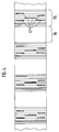
- FIG. 48 A development of the rotary valve 48 is shown in FIG. It can be seen that the rotary valve has seven stages which are formed by the openings 52 of the rotary valve 48. Of these, the first stage represents a closed stage, which determines the basic flow of the shock absorber through leakage. Only four of the six other stages are shown in FIG.
- the permanently excited rotary actuator 13 adjusts the hydraulic throttle cross section in the control slide 14, via which the damper fluid alone flows from one working chamber of the shock absorber to the other working chamber.
- the winding 33 of the electromagnetic rotary actuator 13 is supplied with an alternating current bridge circuit (H circuit), ie two current directions are provided.
- the torque of the turntable arises from the interaction of the coil field and the permanently excited rotor field.
- the direction of the actuating torque is determined by the respective current direction.
- the greatest torque in relation to the reference point is achieved in the position in which the stator and rotor fields form an angle of 90 ° to one another when the armature reaction is neglected.
- the center of the permanent magnetic rotor poles at the air gap faces slot openings 43 and 44 (FIG. 2). Starting from this position, the torque is approximately trapezoidal over an angular range of ⁇ 90 ° for a fixed current.
- the maximum actuating range is set symmetrically to the above position and limited to 30 °.
- Appropriate position control with subordinate current control allows any angle to be set within the active control range.
- the electromagnetic rotary actuator 13 In addition to the respective actuating torque caused by the interaction of the stator and rotor fields, the electromagnetic rotary actuator 13 also has a further torque which results from the attractive force between the magnetic poles and the stator teeth 35 and 36. This cogging torque, which overlaps the actuating torque, also occurs when the coil is de-energized. Depending on the respective position of the same, it rotates the rotor 31 either in the direction of the first or the second stator tooth. The movement is limited in the de-energized state by the stop 27/28.
- the outer surface is divided into control regions 55 and closing regions 56. While the closing areas 56 consist of solid material, the control areas 55 are represented by control slots 57 of different lengths and widths in this embodiment.
- the hydraulic throttle cross section is varied, in seven stages.
- the actual control edge, which is formed by one side of the opening 54, is positioned in the middle between two control slots 57 on a web.
- the basic damping when the opening 54 and the closing area 56 are completely covered is ensured by the basic flow.
- An adaptation of the damper force-angle characteristic of the damper can be achieved in this embodiment by appropriate dimensioning of the slot surfaces. Continuous adjustment possibilities of the throttle cross-section are conceivable as further embodiments, for example rectangular, triangular or open-ended control areas with which the damper force-angle characteristic can be easily adjusted.
Landscapes
- Engineering & Computer Science (AREA)
- General Engineering & Computer Science (AREA)
- Mechanical Engineering (AREA)
- Physics & Mathematics (AREA)
- Acoustics & Sound (AREA)
- Aviation & Aerospace Engineering (AREA)
- Electromagnetism (AREA)
- Vehicle Body Suspensions (AREA)
- Fluid-Damping Devices (AREA)
Applications Claiming Priority (2)
| Application Number | Priority Date | Filing Date | Title |
|---|---|---|---|
| DE3805934A DE3805934A1 (de) | 1988-02-25 | 1988-02-25 | Hydraulischer stossdaempfer |
| DE3805934 | 1988-02-25 |
Publications (3)
| Publication Number | Publication Date |
|---|---|
| EP0329950A2 true EP0329950A2 (fr) | 1989-08-30 |
| EP0329950A3 EP0329950A3 (en) | 1990-03-28 |
| EP0329950B1 EP0329950B1 (fr) | 1993-10-20 |
Family
ID=6348165
Family Applications (1)
| Application Number | Title | Priority Date | Filing Date |
|---|---|---|---|
| EP89101054A Expired - Lifetime EP0329950B1 (fr) | 1988-02-25 | 1989-01-21 | Amortisseur hydraulique |
Country Status (5)
| Country | Link |
|---|---|
| US (1) | US4926983A (fr) |
| EP (1) | EP0329950B1 (fr) |
| JP (1) | JPH01249508A (fr) |
| KR (1) | KR890013378A (fr) |
| DE (2) | DE3805934A1 (fr) |
Cited By (6)
| Publication number | Priority date | Publication date | Assignee | Title |
|---|---|---|---|---|
| WO1991000189A1 (fr) * | 1989-06-29 | 1991-01-10 | Robert Bosch Gmbh | Regulation du chassis avec circuit d'adaptation a element de reglage |
| EP0451499A1 (fr) * | 1990-04-07 | 1991-10-16 | AUGUST BILSTEIN GMBH & CO. KG | Amortisseur de vibrations réglable pour véhicules automobiles |
| EP0544481A1 (fr) * | 1991-11-27 | 1993-06-02 | Lord Corporation | Soupape améliorée pour un amortisseur de chocs réglable |
| DE102011102835A1 (de) | 2011-05-30 | 2012-12-06 | Audi Ag | Hydraulischer Stoßdämpfer mit Proportionalmagneten |
| CN104776152A (zh) * | 2015-04-08 | 2015-07-15 | 重庆大学 | 高效能低功耗磁流变半主动与主动一体化减振装置 |
| EP3029350A1 (fr) * | 2014-12-02 | 2016-06-08 | Cycling Sports Group, Inc. | Ensemble de soupape pour système de suspension de bicyclette |
Families Citing this family (18)
| Publication number | Priority date | Publication date | Assignee | Title |
|---|---|---|---|---|
| US5217095A (en) * | 1986-06-05 | 1993-06-08 | Monroe Auto Equipment Company | Method and apparatus for absorbing mechanical shock |
| CA1263414A (fr) * | 1986-06-05 | 1989-11-28 | Magnus Lizell | Dispositif a etrangleur pour fluides de pression hydraulique dans des mecanismes amortisseurs de chocs |
| US5305860A (en) * | 1989-03-03 | 1994-04-26 | Maremont Corporation | Remote controlled vehicle damper |
| JPH07106051B2 (ja) * | 1989-04-21 | 1995-11-13 | 三菱電機株式会社 | アクチュエータ |
| DE3940290C1 (en) * | 1989-12-06 | 1991-07-11 | August Bilstein Gmbh & Co Kg, 5828 Ennepetal, De | By=pass valve drive for hydraulic vibration damper - has electro-rotor fixed to control disc via toothed rod |
| DE4002883A1 (de) * | 1990-02-01 | 1991-08-08 | Bilstein August Gmbh Co Kg | Schwingungsdaempfersteuerventil eines bypasses mit selbsthaltung |
| DE4039236C1 (en) * | 1990-02-01 | 1992-05-27 | August Bilstein Gmbh & Co. Kg, 5828 Ennepetal, De | Control valve for hydraulic shock absorber of motor vehicle - uses electromagnet to increase force of permanent magnet and open by=pass against mechanical spring force closing by=pass |
| US5307907A (en) * | 1991-06-11 | 1994-05-03 | Atsugi Unisia Corporation | Hydraulic damper |
| DE4142862C2 (de) * | 1991-12-23 | 1994-06-16 | Bilstein August Gmbh Co Kg | Regelbarer Schwingungsdämpfer für Kraftfahrzeuge |
| US5350187A (en) * | 1992-10-16 | 1994-09-27 | Monroe Auto Equipment Company | Adjustable damping system |
| JP3383863B2 (ja) * | 1993-03-08 | 2003-03-10 | トキコ株式会社 | 減衰力調整式油圧緩衝器 |
| KR970000624B1 (ko) * | 1994-10-26 | 1997-01-16 | 대우전자 주식회사 | 자동차용 ABS장치(Anti-lock Brakesystem)의 콘트롤 밸브(control valve) |
| US6286642B1 (en) * | 1999-10-18 | 2001-09-11 | Giant Mfg. Co., Ltd | Fluid regulating device for use with a shock-absorbing cylinder to obtain a variable shock absorbing effect |
| US8733519B2 (en) * | 2009-01-23 | 2014-05-27 | Jri Development Group, Llc | Linear impelled module damper |
| US8235186B2 (en) * | 2009-10-07 | 2012-08-07 | Multimatic Inc. | Hydraulic damper spool valve |
| DE102014215566B3 (de) * | 2014-08-06 | 2016-01-21 | Zf Friedrichshafen Ag | Dämpfventil |
| DE102015201957A1 (de) * | 2015-02-04 | 2016-08-04 | Volkswagen Aktiengesellschaft | Hydraulischer Schwingungsdämpfer |
| CN112303167B (zh) * | 2020-11-19 | 2022-05-17 | 扬中市兴鸿车辆配件有限公司 | 一种阻尼独立悬挂的液压减震器及其液压阻尼系统 |
Family Cites Families (14)
| Publication number | Priority date | Publication date | Assignee | Title |
|---|---|---|---|---|
| GB664770A (en) * | 1949-03-30 | 1952-01-09 | Woodhead Monroe Ltd | Improvements in hydraulic shock absorbers |
| DE1084528B (de) * | 1958-06-10 | 1960-06-30 | Hoesch Ag | Regelbarer hydraulischer Stossdaempfer |
| JPS5872546U (ja) * | 1981-11-12 | 1983-05-17 | トキコ株式会社 | 減衰力調整式油圧緩衝器 |
| US4527676A (en) * | 1982-02-13 | 1985-07-09 | Atsugi Motor Parts Co., Ltd. | Variable-damping-force shock absorber |
| US4526401A (en) * | 1982-11-30 | 1985-07-02 | Atsugi Motor Parts Co., Ltd. | Electronic control system for adjustable shock absorbers |
| DE8336759U1 (de) * | 1983-04-11 | 1985-11-28 | F & O Electronic Systems GmbH & Co, 6901 Neckarsteinach | Stoßdämpfer mit veränderbarer Dämpfungscharakteristik |
| DE3312899C2 (de) * | 1983-04-11 | 1985-06-13 | F & O Electronic Systems GmbH & Co, 6901 Neckarsteinach | Regelbares Ventil für die Kolbenstange eines Schwingungsdämpfers |
| JPS6026345U (ja) * | 1983-07-29 | 1985-02-22 | トキコ株式会社 | ハイドロ・ニュ−マチック サスペンション |
| GB2147683B (en) * | 1983-09-24 | 1986-10-01 | Bilstein August Gmbh Co Kg | Shock absorber, with electromagnetically biased pressure responsive valve |
| JPS60103734U (ja) * | 1983-12-21 | 1985-07-15 | 自動車電機工業株式会社 | 油圧緩衝器 |
| DE3446133A1 (de) * | 1984-12-18 | 1986-06-19 | Fichtel & Sachs Ag, 8720 Schweinfurt | Schwingungsdaempfer mit veraenderbarer daempfkraft |
| DE3584151D1 (de) * | 1984-12-27 | 1991-10-24 | Nippon Denso Co | Elektromagnetisches stroemungsregelungsventil. |
| JPS6267342A (ja) * | 1985-09-19 | 1987-03-27 | Aisin Seiki Co Ltd | 回転角度制御用ロ−タリ−アクチユエ−タ |
| DE3635894A1 (de) * | 1986-10-22 | 1988-05-05 | Bosch Gmbh Robert | Stossdaempfer |
-
1988
- 1988-02-25 DE DE3805934A patent/DE3805934A1/de not_active Withdrawn
-
1989
- 1989-01-21 EP EP89101054A patent/EP0329950B1/fr not_active Expired - Lifetime
- 1989-01-21 DE DE89101054T patent/DE58905930D1/de not_active Expired - Fee Related
- 1989-01-24 US US07/300,872 patent/US4926983A/en not_active Expired - Lifetime
- 1989-02-21 JP JP1039481A patent/JPH01249508A/ja active Pending
- 1989-02-24 KR KR1019890002163A patent/KR890013378A/ko not_active Withdrawn
Cited By (7)
| Publication number | Priority date | Publication date | Assignee | Title |
|---|---|---|---|---|
| WO1991000189A1 (fr) * | 1989-06-29 | 1991-01-10 | Robert Bosch Gmbh | Regulation du chassis avec circuit d'adaptation a element de reglage |
| EP0451499A1 (fr) * | 1990-04-07 | 1991-10-16 | AUGUST BILSTEIN GMBH & CO. KG | Amortisseur de vibrations réglable pour véhicules automobiles |
| EP0544481A1 (fr) * | 1991-11-27 | 1993-06-02 | Lord Corporation | Soupape améliorée pour un amortisseur de chocs réglable |
| DE102011102835A1 (de) | 2011-05-30 | 2012-12-06 | Audi Ag | Hydraulischer Stoßdämpfer mit Proportionalmagneten |
| DE102011102835B4 (de) * | 2011-05-30 | 2015-07-02 | Audi Ag | Hydraulischer Stoßdämpfer mit Proportionalmagneten |
| EP3029350A1 (fr) * | 2014-12-02 | 2016-06-08 | Cycling Sports Group, Inc. | Ensemble de soupape pour système de suspension de bicyclette |
| CN104776152A (zh) * | 2015-04-08 | 2015-07-15 | 重庆大学 | 高效能低功耗磁流变半主动与主动一体化减振装置 |
Also Published As
| Publication number | Publication date |
|---|---|
| EP0329950A3 (en) | 1990-03-28 |
| DE58905930D1 (de) | 1993-11-25 |
| US4926983A (en) | 1990-05-22 |
| KR890013378A (ko) | 1989-09-22 |
| DE3805934A1 (de) | 1989-09-07 |
| JPH01249508A (ja) | 1989-10-04 |
| EP0329950B1 (fr) | 1993-10-20 |
Similar Documents
| Publication | Publication Date | Title |
|---|---|---|
| EP0329950B1 (fr) | Amortisseur hydraulique | |
| DE3009735C2 (de) | Elektrischer Linearmotor | |
| EP0122575B1 (fr) | Amortisseur autorégulateur à un ou deux tubes, en particulier pour véhicules à moteur | |
| DE69325669T2 (de) | Linearmotor für ein ventil | |
| EP0450288B1 (fr) | Moteur électrique linéaire | |
| WO2010086058A1 (fr) | Aimant proportionnel pour un distributeur hydraulique et son procédé de fabrication | |
| DE19743314A1 (de) | Bürstenloser Motor mit Permanentmagneten | |
| EP0285909A1 (fr) | Amortisseur de chocs | |
| DE4211913A1 (de) | Magnetbetaetigtes druckregelventil | |
| EP0288736A2 (fr) | Amortisseur de chocs I | |
| DE3312899C2 (de) | Regelbares Ventil für die Kolbenstange eines Schwingungsdämpfers | |
| DE68913209T2 (de) | Elektrisch betätigbares ventil für kraftstoff-einspritzanlagen für brennkraftmaschinen. | |
| DE68908539T2 (de) | Vorrichtung mit Betätiger, dessen Verwendungsverfahren in der Vorrichtung und Gerät zum Steuern eines Gas- oder Flüssigkeitsstromes, versehen mit der Vorrichtung. | |
| EP0937328B1 (fr) | Mecanisme de reglage a moteur electrique | |
| EP0383065B1 (fr) | Soupape pour l'introduction intermittente de carburant | |
| DE3635894A1 (de) | Stossdaempfer | |
| DE8711725U1 (de) | Elektrokleinmotor | |
| DE69709922T2 (de) | Stellglied mit minimiertem hilfsmagnet, und drosselvorrichtung mit einem solchen stellglied | |
| EP0211442A1 (fr) | Soupape réglable pour un amortisseur de vibrations | |
| DE4214284A1 (de) | Elektromagnetischer linearmotor | |
| DE2458516A1 (de) | Elektromagnetische betaetigungseinrichtung | |
| DE4137602A1 (de) | Gummilager | |
| DE68906612T2 (de) | Kraftmotor. | |
| DE2952786A1 (de) | Drehzahlregler fuer verbrennungsmotoren | |
| DE2341766C3 (de) | Magnetische Lagerung |
Legal Events
| Date | Code | Title | Description |
|---|---|---|---|
| PUAI | Public reference made under article 153(3) epc to a published international application that has entered the european phase |
Free format text: ORIGINAL CODE: 0009012 |
|
| AK | Designated contracting states |
Kind code of ref document: A2 Designated state(s): DE FR GB SE |
|
| PUAL | Search report despatched |
Free format text: ORIGINAL CODE: 0009013 |
|
| AK | Designated contracting states |
Kind code of ref document: A3 Designated state(s): DE FR GB SE |
|
| 17P | Request for examination filed |
Effective date: 19900912 |
|
| RAP3 | Party data changed (applicant data changed or rights of an application transferred) |
Owner name: ROBERT BOSCH GMBH |
|
| 17Q | First examination report despatched |
Effective date: 19920422 |
|
| GRAA | (expected) grant |
Free format text: ORIGINAL CODE: 0009210 |
|
| AK | Designated contracting states |
Kind code of ref document: B1 Designated state(s): DE FR GB SE |
|
| PG25 | Lapsed in a contracting state [announced via postgrant information from national office to epo] |
Ref country code: SE Effective date: 19931020 |
|
| REF | Corresponds to: |
Ref document number: 58905930 Country of ref document: DE Date of ref document: 19931125 |
|
| GBT | Gb: translation of ep patent filed (gb section 77(6)(a)/1977) |
Effective date: 19931028 |
|
| ET | Fr: translation filed | ||
| PLBE | No opposition filed within time limit |
Free format text: ORIGINAL CODE: 0009261 |
|
| STAA | Information on the status of an ep patent application or granted ep patent |
Free format text: STATUS: NO OPPOSITION FILED WITHIN TIME LIMIT |
|
| 26N | No opposition filed | ||
| PGFP | Annual fee paid to national office [announced via postgrant information from national office to epo] |
Ref country code: GB Payment date: 19950111 Year of fee payment: 7 |
|
| PGFP | Annual fee paid to national office [announced via postgrant information from national office to epo] |
Ref country code: FR Payment date: 19950131 Year of fee payment: 7 |
|
| PG25 | Lapsed in a contracting state [announced via postgrant information from national office to epo] |
Ref country code: GB Effective date: 19960121 |
|
| GBPC | Gb: european patent ceased through non-payment of renewal fee |
Effective date: 19960121 |
|
| PG25 | Lapsed in a contracting state [announced via postgrant information from national office to epo] |
Ref country code: FR Effective date: 19960930 |
|
| REG | Reference to a national code |
Ref country code: FR Ref legal event code: ST |
|
| PGFP | Annual fee paid to national office [announced via postgrant information from national office to epo] |
Ref country code: DE Payment date: 20030225 Year of fee payment: 15 |
|
| PG25 | Lapsed in a contracting state [announced via postgrant information from national office to epo] |
Ref country code: DE Free format text: LAPSE BECAUSE OF NON-PAYMENT OF DUE FEES Effective date: 20040803 |