EP0330053A2 - Dispositif et méthode pour commander l'alimentation d'un fil de jonction au coin ou au capillaire d'une tête de jonction - Google Patents
Dispositif et méthode pour commander l'alimentation d'un fil de jonction au coin ou au capillaire d'une tête de jonction Download PDFInfo
- Publication number
- EP0330053A2 EP0330053A2 EP89102516A EP89102516A EP0330053A2 EP 0330053 A2 EP0330053 A2 EP 0330053A2 EP 89102516 A EP89102516 A EP 89102516A EP 89102516 A EP89102516 A EP 89102516A EP 0330053 A2 EP0330053 A2 EP 0330053A2
- Authority
- EP
- European Patent Office
- Prior art keywords
- bond
- wire
- capillary
- bonding
- clamp
- Prior art date
- Legal status (The legal status is an assumption and is not a legal conclusion. Google has not performed a legal analysis and makes no representation as to the accuracy of the status listed.)
- Granted
Links
Images
Classifications
-
- H—ELECTRICITY
- H05—ELECTRIC TECHNIQUES NOT OTHERWISE PROVIDED FOR
- H05K—PRINTED CIRCUITS; CASINGS OR CONSTRUCTIONAL DETAILS OF ELECTRIC APPARATUS; MANUFACTURE OF ASSEMBLAGES OF ELECTRICAL COMPONENTS
- H05K5/00—Casings, cabinets or drawers for electric apparatus
-
- B—PERFORMING OPERATIONS; TRANSPORTING
- B23—MACHINE TOOLS; METAL-WORKING NOT OTHERWISE PROVIDED FOR
- B23K—SOLDERING OR UNSOLDERING; WELDING; CLADDING OR PLATING BY SOLDERING OR WELDING; CUTTING BY APPLYING HEAT LOCALLY, e.g. FLAME CUTTING; WORKING BY LASER BEAM
- B23K20/00—Non-electric welding by applying impact or other pressure, with or without the application of heat, e.g. cladding or plating
- B23K20/002—Non-electric welding by applying impact or other pressure, with or without the application of heat, e.g. cladding or plating specially adapted for particular articles or work
- B23K20/004—Wire welding
- B23K20/005—Capillary welding
- B23K20/007—Ball bonding
-
- H—ELECTRICITY
- H10—SEMICONDUCTOR DEVICES; ELECTRIC SOLID-STATE DEVICES NOT OTHERWISE PROVIDED FOR
- H10W—GENERIC PACKAGES, INTERCONNECTIONS, CONNECTORS OR OTHER CONSTRUCTIONAL DETAILS OF DEVICES COVERED BY CLASS H10
- H10W72/00—Interconnections or connectors in packages
- H10W72/071—Connecting or disconnecting
- H10W72/0711—Apparatus therefor
- H10W72/07141—Means for applying energy, e.g. ovens or lasers
-
- H—ELECTRICITY
- H10—SEMICONDUCTOR DEVICES; ELECTRIC SOLID-STATE DEVICES NOT OTHERWISE PROVIDED FOR
- H10W—GENERIC PACKAGES, INTERCONNECTIONS, CONNECTORS OR OTHER CONSTRUCTIONAL DETAILS OF DEVICES COVERED BY CLASS H10
- H10W72/00—Interconnections or connectors in packages
- H10W72/071—Connecting or disconnecting
- H10W72/0711—Apparatus therefor
- H10W72/07168—Means for storing or moving the material for the connector
-
- H—ELECTRICITY
- H10—SEMICONDUCTOR DEVICES; ELECTRIC SOLID-STATE DEVICES NOT OTHERWISE PROVIDED FOR
- H10W—GENERIC PACKAGES, INTERCONNECTIONS, CONNECTORS OR OTHER CONSTRUCTIONAL DETAILS OF DEVICES COVERED BY CLASS H10
- H10W72/00—Interconnections or connectors in packages
- H10W72/071—Connecting or disconnecting
- H10W72/075—Connecting or disconnecting of bond wires
- H10W72/07502—Connecting or disconnecting of bond wires using an auxiliary member
-
- H—ELECTRICITY
- H10—SEMICONDUCTOR DEVICES; ELECTRIC SOLID-STATE DEVICES NOT OTHERWISE PROVIDED FOR
- H10W—GENERIC PACKAGES, INTERCONNECTIONS, CONNECTORS OR OTHER CONSTRUCTIONAL DETAILS OF DEVICES COVERED BY CLASS H10
- H10W72/00—Interconnections or connectors in packages
- H10W72/071—Connecting or disconnecting
- H10W72/075—Connecting or disconnecting of bond wires
- H10W72/07521—Aligning
-
- H—ELECTRICITY
- H10—SEMICONDUCTOR DEVICES; ELECTRIC SOLID-STATE DEVICES NOT OTHERWISE PROVIDED FOR
- H10W—GENERIC PACKAGES, INTERCONNECTIONS, CONNECTORS OR OTHER CONSTRUCTIONAL DETAILS OF DEVICES COVERED BY CLASS H10
- H10W72/00—Interconnections or connectors in packages
- H10W72/071—Connecting or disconnecting
- H10W72/075—Connecting or disconnecting of bond wires
- H10W72/07531—Techniques
- H10W72/07532—Compression bonding, e.g. thermocompression bonding
- H10W72/07533—Ultrasonic bonding, e.g. thermosonic bonding
-
- H—ELECTRICITY
- H10—SEMICONDUCTOR DEVICES; ELECTRIC SOLID-STATE DEVICES NOT OTHERWISE PROVIDED FOR
- H10W—GENERIC PACKAGES, INTERCONNECTIONS, CONNECTORS OR OTHER CONSTRUCTIONAL DETAILS OF DEVICES COVERED BY CLASS H10
- H10W72/00—Interconnections or connectors in packages
- H10W72/50—Bond wires
- H10W72/531—Shapes of wire connectors
- H10W72/536—Shapes of wire connectors the connected ends being ball-shaped
-
- H—ELECTRICITY
- H10—SEMICONDUCTOR DEVICES; ELECTRIC SOLID-STATE DEVICES NOT OTHERWISE PROVIDED FOR
- H10W—GENERIC PACKAGES, INTERCONNECTIONS, CONNECTORS OR OTHER CONSTRUCTIONAL DETAILS OF DEVICES COVERED BY CLASS H10
- H10W72/00—Interconnections or connectors in packages
- H10W72/50—Bond wires
- H10W72/531—Shapes of wire connectors
- H10W72/5363—Shapes of wire connectors the connected ends being wedge-shaped
-
- H—ELECTRICITY
- H10—SEMICONDUCTOR DEVICES; ELECTRIC SOLID-STATE DEVICES NOT OTHERWISE PROVIDED FOR
- H10W—GENERIC PACKAGES, INTERCONNECTIONS, CONNECTORS OR OTHER CONSTRUCTIONAL DETAILS OF DEVICES COVERED BY CLASS H10
- H10W72/00—Interconnections or connectors in packages
- H10W72/50—Bond wires
- H10W72/551—Materials of bond wires
- H10W72/552—Materials of bond wires comprising metals or metalloids, e.g. silver
- H10W72/5522—Materials of bond wires comprising metals or metalloids, e.g. silver comprising gold [Au]
Definitions
- the invention relates to a device and a method for the controlled feeding of a bonding wire, in particular gold bonding wire for "wedge” or for the capillary of a bonding head.
- bonding is generally understood to mean connecting components to one another by gluing or welding, in contrast to conventional soldering, where the connection is made using a solder (usually a tin-lead alloy).
- chip (die) bonding processes for attaching a component to a carrier substrate
- wire bonding processes for connecting the component connections to the carrier substrate by means of fine wires.
- the invention relates to a detail of the latter method.
- thermocompression bonding also known as nail-head-ball bonding, and so-called ultrasonic wedge bonding.
- thermocompressine and ultrasonic wedge bonding is the so-called thermosonic bonding. This method is becoming increasingly popular.
- Gold wire is mostly used here, which is melted into a ball similar to ball bonding.
- the welding is carried out at moderate heat using ultrasound. This process is relatively easy to control and can also be automated.
- reference is made to US-A-34 59 355, 33 57 090 and 31 28 649 or DE-A-33 35 840 and DE-C-35 37 551, which provide a certain overview of the bonding technique mentioned .
- the bonding wire is either pulled to the bond point (clamps) by means of clamps or pliers or, after bonding, is pulled away from it again to tear off the bond wire.
- clamps and pliers mentioned are open, with the result that the bond wire can be pulled in relatively without resistance.
- this in turn means that the length of the drawn wire and thus the loop size is dependent of randomly occurring resistances on the wire coil and in the wire guide. With larger loops it has been shown that the wire length required for loop formation is very often too small. The opposite often occurs with smaller loops.
- the present invention is therefore based on the object of controlling the feeding of the bonding wire in such a way that a predetermined loop size is maintained during the entire operation of the bonder and the so-called "golf stroke" is additionally avoided during ball bonding, the mechanical action on the Bond wire is said to be a minimum.
- the bond wire is pushed during the bonding process, in particular during the loop formation, in the direction of the "wedge" or to the capillary of the bond head or a train is pulled onto the bond wire
- Direction is exerted away from the "wedge” or the capillary of the bonding head while maintaining an approximately constant wire tension, for this purpose the "wedge" or the bond capillary is preceded by a bond wire guide channel, into which a fluid connection optionally connected to a compressed gas, in particular compressed air or vacuum source opens.
- the bond wire Due to the fluid action on the bond wire, this can be pushed or held back or braked as required and possibly without mechanical action while maintaining a substantially constant wire tension, which means that a predetermined wire length for the formation of a loop is maintained relatively precisely and additionally during ball bonding so-called "golf shot” can be avoided.
- the bond wire With smaller loops and with the "touch-down" of the "ball", the bond wire is usually braked fluidically; in the case of larger loops, the bond wire is preferably fluidically fed.
- the normal drawing of the bonding wire before a new bonding process can also be carried out purely fluidly using the system mentioned. A mechanical action on the bond wire is then only required when the bond wire is torn off. This is an advantage for thin and delicate gold wire.
- CH-A-592 365 it is known per se from CH-A-592 365 to control the bonding wire voltage by means of an external gas flow.
- the gas flow there does not act directly on the bond wire in the sense of a fluidic feed or a fluidic "deceleration", but only indirectly via a fluidically rotating pipe loop through which the bond wire is guided to the bond site.
- the construction according to CH-A-592 365 is not intended to influence the bond wire voltage by connecting a vacuum source.
- a bond wire slip clamp which is assigned to the bond wire guide channel and is arranged either in front of or at the end of the capillary, which is either permanently or only effective or closed when the bond head is lowered to "touch-down" .
- the bond wire slip clamp is preferably a clamp whose effective clamping surfaces are coated with felt or the like. In this way, the bond wire can be pulled through the clamp while maintaining a predetermined voltage.
- the bond wire slip clamp provided according to the invention in addition to maintaining a predetermined bond wire voltage and thus bond wire stiffness, also has the great advantage that an intrinsic twist is "removed or pulled" from the bond wire, with the result that loop- Formation of the bond wire can no longer be discarded uncontrollably. Accordingly, the slip clamp provided according to the invention allows the formation of exact loops.
- the slip clamp is controllable, i. H. can be opened and closed depending on the up and down movement of the bondhead and the corresponding effect on the bond wire.
- the arrangement according to the invention of the slip clamp on the capillary-side end of the bond wire guide channel is particularly effective due to the proximity to the bond head.
- the formation of the overpressure or underpressure in the guide channel is no longer influenced by the arrangement of the slip clamp on the capillary-side end of the guide channel.
- a fixed bond wire clamp is arranged downstream of the bond wire guide channel, which can be closed or opened depending on the height of the bond head or the distance of the capillary tip from the bond point, with retraction and corresponding removal of a bond wire section hanging down from the capillary tip immediately before the "touch-down".
- the bonding is preferably carried out in accordance with the methods described in claims 10 to 12 or 13 and / or 14.
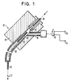
- connection 15 optionally connected to a compressed gas source, namely compressed air source 13 or negative pressure source 14, opens.
- the last-mentioned connection 15 is assigned a changeover valve 16, by means of which the connection 15 can be connected either to the compressed air source 13 or to the vacuum source 14.
- the changeover valve 16 is coupled to the sequence control of the bonder or its bonding head, which is not shown in detail.
- the bond wire guide 12 has a mounting block 17 with a through hole 18, on the coil-side end of which a wire guide nozzle 19 is fixed, while a wire guide tube 20 is inserted at the wedge or capillary end of the through hole 18.
- the connector 15, which can be connected to the compressed air or vacuum source, is located directly behind the wire guide nozzle 19. It opens into the through hole 18 between the wire guide nozzle 19 and the wire guide tube 20.
- the wire guide nozzle 19 is designed similarly to a bond capillary. It has at its wedge or capillary end a nozzle-like constriction through which the bonding wire 10 coming from the wire coil (not shown) is threaded.
- the threading and, if necessary, feeding of the bonding wire 10 to the wedge or to the bond capillary is carried out with compressed air support, in that compressed air is blown into the through-bore 18 through the connection 15 when the valve 16 is switched accordingly.
- the connection 15 opens into the through hole 18 at an acute angle to the longitudinal axis of the wire guide nozzle 19, so that when compressed air is introduced into the through hole 18, the bonding wire 10 through the bond wire guide 12 is pushed fluidically.
- a coaxial flow in the direction of the wedge or the bond capillary forms within the through hole 18 and the wire guide tube 20 around the bond wire 10. This coaxial air flow causes the bonding wire 10 to be pushed forward, depending on the intensity of the air blown in.
- the minimum inside diameter of the constriction of the wire guide nozzle 19 on the outlet side is approximately 100 .mu.m to 130 .mu.m.
- the through hole 18 and the wire guide tube have an inner diameter of approximately 1.5 mm to 2.2 mm. The resulting diameter ratios apply generally.
- connection 15 When the connection 15 is connected to the vacuum source 14, the bonding wire 10 is literally braked while maintaining an essentially constant wire voltage. It is thereby prevented that too much bonding wire is drawn in during loop formation, with the result of a disproportionately large loop.
- larger loops are formed, on the other hand, it is advantageous if compressed air is blown in through the connection 15. As a result, the bond wire 10 is literally pushed in so that there is sufficient wire for loop formation.
- the device described is therefore also particularly suitable when loops of different sizes have to be formed in succession.
- the corresponding control of the fluidic action on the bond wire takes place via the valve 16 in dependence on the bond head control commands.
- the coaxial flow preferably has a swirl component around the bond wire, as a result of which it is literally centered within the through hole 18 and the guide tube 20.
- the guide tube 20 is bent vertically downward toward the “wedge” or toward the bond capillary.
- the device shown and the method described can be retrofitted and used in conventional bonding devices.
- the device described and the method described for gold wire bonding have proven to be particularly advantageous.
- the fluidic action on the bond wire can preferably be made variable, for. B. with regard to pressure and air flow with a corresponding change in the wire tension in adaptation to different process stages of the bondhead.
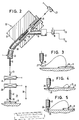
- the construction according to FIG. 2 differs from that according to FIG. 1 by the arrangement of a bond wire slip clamp 23 which either precedes the bond wire guide channel 12, 18, 19, 20 (as shown in FIG. 1 in full) or on the capillary side End of the same, namely at the capillary-side end of the bond wire guide tube 20 (as indicated by dashed lines in FIG. 1), the bond wire slip clamp 23 being either permanently or only effective or closed when the bond head 21 is lowered to the so-called “touch-down” is.
- the bond wire slip clamp 23 is preferably a clamp, the effective clamping surfaces of which are provided with a felt covering or the like, so that the bond wire 10 can still be pulled through when the clamp 23 is closed, but while maintaining a predetermined wire tension and rigidity and with removal a possible twist in the wire. This results in much stiffer loops compared to the prior art that are also free of twist-related distortions. In the loops produced using the described slip clamp 23 there is no danger that they will collapse with the formation of faulty contacts according to FIG. 4. Rather, a loop configuration according to FIG. 5 is obtained. In addition, in the embodiment according to FIG.
- the bond wire guide channel 12, 18, 19, 20, specifically the guide tube 20 is followed by a fixed bond wire clamp 24, that is to say one that cannot be moved with the bond head 21 and which depends on the The height of the bond head 21 or the distance of the capillary tip 26 from the bond point 25 can be closed or opened by withdrawing and correspondingly removing a bond wire section 27 which hangs downward from the capillary tip 26 (see FIG. 3) immediately before the "touch-down" .
- a further bond wire clamp 28 is assigned to the capillary 22, which can be moved up and down with the bond head 21.
- the bonding wire 10 is fed to the capillary 22 using the clamps 24, 28 and the slip clamp 23 as follows:
- the bonding head 21 is lowered from a raised starting or starting position by taking the bonding wire 10 with it by means of the clamp 28 arranged on the bonding head 21, the taking of the bonding wire 10 counter to the action of a coaxial fluid flow in the bonding wire which keeps the bonding wire 10 under low tensile stress. Guide channel and against the action of the slip clamp 23 with previous or simultaneous formation of a "ball" at the free end of the bonding wire 10.
- the bonding wire 10 is both fluidically in the bonding wire Guide channel (connection of the vacuum source 14) and mechanically kept under tension by the bond wire slip clamp 23.
- the bond wire clamp 28 moved with the capillary 22 is opened, so that the "ball” formed at the free end of the bond wire 10 abuts the conical or ball socket-shaped capillary tip 26 while avoiding the described "golf stroke” "arrives. Then the "touch-down” takes place with simultaneous ultrasound excitation of the capillary 22 and formation of a first bond 25.
- the bond head 21 together with the capillary 22 is raised again, to a predetermined loop height, preferably by opening the slip clamp 23, provided that it is a controllable one Slip clamp acts, and if necessary by switching off or switching over the coaxial fluid flow according to the size of the loop to be formed (see above explanations).
- the second bond point 29 is then positioned relative to the capillary 22.
- the bond head 21 together with the capillary 22 is lowered, taking the bond wire 10 with it, again against the effect of the coaxial fluid flow described and, if appropriate, again closed slip clamp 23 until the renewed or second " touch-down "and formation of a second bond 29 under the action of ultrasound.
- the clamp 24 arranged in a fixed manner above the bonding head 21 closes by fixing the bonding wire 10 or correspondingly withdrawing the bonding wire 10 by the capillary 22 moved downward a bond wire section 27 hanging downward from the capillary tip 26 corresponding to FIG. 3 is removed immediately before the second “touch-down”.
- the clamp 24 closes at a predetermined or preprogrammed height of the bonding head 21 or the capillary 22 depending on the material of the bonding wire 10 and the size of the loop.
- the clamp 24 is opened again.
- the bond head 21 is then raised again, namely up to the so-called tail-length height.
- the slip clamp 23 is preferably also opened, provided that it is a controllable slip clamp.
- the coaxial flow described, which retains the bond wire 10 is preferably still effective. This applies in particular when the slip clamp 23 is arranged at the capillary-side end of the bond wire guide tube 20.
- the switching of the coaxial flow ie switching on and switching off and direction, depends on the inherent rigidity, ie the material and diameter of the bonding wire 10.
- the bond wire clamps 24, 28 are conventional wire clamping devices, so that a more detailed illustration and description of the same appears to be unnecessary. The situation is similar with the formation of the capillary 22.
- the slip clamp 23 is a conventional one Wire clip formed, only with the difference that the clamping surfaces are provided with a felt covering or the like. In such a way that the bond wire 10 can still be pulled even when the clamping device is closed.
- the clamping force of the slip clamp 23 is preferably adjustable, in particular variable with adaptation to different bonding wires (material and diameter).
- the device according to FIG. 2 can also be retrofitted or used in conventional bonders.
Landscapes
- Engineering & Computer Science (AREA)
- Mechanical Engineering (AREA)
- Microelectronics & Electronic Packaging (AREA)
- Wire Bonding (AREA)
Applications Claiming Priority (4)
| Application Number | Priority Date | Filing Date | Title |
|---|---|---|---|
| DE3805584A DE3805584A1 (de) | 1988-02-23 | 1988-02-23 | Vorrichtung und verfahren zur gesteuerten zufuehrung eines bonddrahtes zum "wedge" oder zur kapillare eines bondkopfes |
| DE3805584 | 1988-02-23 | ||
| DE3825373 | 1988-07-26 | ||
| DE3825373A DE3825373A1 (de) | 1988-07-26 | 1988-07-26 | Vorrichtung und verfahren zur gesteuerten zufuehrung eines bonddrahtes zum "wedge" oder zur kapillare eines bondkopfes |
Publications (3)
| Publication Number | Publication Date |
|---|---|
| EP0330053A2 true EP0330053A2 (fr) | 1989-08-30 |
| EP0330053A3 EP0330053A3 (en) | 1990-03-21 |
| EP0330053B1 EP0330053B1 (fr) | 1994-08-03 |
Family
ID=25865111
Family Applications (1)
| Application Number | Title | Priority Date | Filing Date |
|---|---|---|---|
| EP19890102516 Expired - Lifetime EP0330053B1 (fr) | 1988-02-23 | 1989-02-14 | Dispositif et méthode pour commander l'alimentation d'un fil de jonction au coin ou au capillaire d'une tête de jonction |
Country Status (6)
| Country | Link |
|---|---|
| US (1) | US4928871A (fr) |
| EP (1) | EP0330053B1 (fr) |
| JP (1) | JPH01302736A (fr) |
| KR (1) | KR900002673A (fr) |
| AT (1) | ATE109387T1 (fr) |
| DE (1) | DE58908123D1 (fr) |
Cited By (2)
| Publication number | Priority date | Publication date | Assignee | Title |
|---|---|---|---|---|
| WO1999015452A1 (fr) * | 1997-09-20 | 1999-04-01 | Hesse & Knipps Gmbh | Frein pour fil |
| CN106001577A (zh) * | 2016-06-27 | 2016-10-12 | 西安智熔金属打印系统有限公司 | 基于增材制造技术的送丝机构、送丝装置及增材制造设备 |
Families Citing this family (20)
| Publication number | Priority date | Publication date | Assignee | Title |
|---|---|---|---|---|
| JP2559539B2 (ja) * | 1991-03-13 | 1996-12-04 | ローム株式会社 | ボンディング装置 |
| US20070228110A1 (en) * | 1993-11-16 | 2007-10-04 | Formfactor, Inc. | Method Of Wirebonding That Utilizes A Gas Flow Within A Capillary From Which A Wire Is Played Out |
| JP3075100B2 (ja) * | 1994-10-06 | 2000-08-07 | 松下電器産業株式会社 | ワイヤボンディング装置およびワイヤボンディング方法 |
| JPH0945721A (ja) * | 1995-08-03 | 1997-02-14 | Kaijo Corp | ワイヤ案内装置及びワイヤ案内方法並びに該装置を具備したワイヤボンディング装置 |
| DE19617470B4 (de) * | 1995-11-07 | 2006-02-02 | Hesse & Knipps Gmbh | Fadenzuführung |
| JP3741184B2 (ja) * | 1998-07-27 | 2006-02-01 | 日本テキサス・インスツルメンツ株式会社 | 半導体装置 |
| JP2000082717A (ja) * | 1998-09-07 | 2000-03-21 | Shinkawa Ltd | ワイヤボンディング方法 |
| AU720299B3 (en) * | 2000-03-09 | 2000-05-25 | Edmunds Gumbelis | Feeding machanism for welding wire |
| JP2002064117A (ja) * | 2000-08-22 | 2002-02-28 | Mitsubishi Electric Corp | ワイヤボンディング方法、ワイヤボンディング装置および半導体装置 |
| JP2002083837A (ja) * | 2000-09-07 | 2002-03-22 | Shinkawa Ltd | ワイヤボンディング装置 |
| JP2002151545A (ja) * | 2000-11-10 | 2002-05-24 | Nec Corp | ワイヤボンディング装置 |
| US6641025B2 (en) * | 2001-08-30 | 2003-11-04 | Micron Technology, Inc. | Threading tool and method for bond wire capillary tubes |
| US7311239B2 (en) * | 2004-05-04 | 2007-12-25 | Sv Probe Pte Ltd. | Probe attach tool |
| US7954689B2 (en) * | 2007-05-04 | 2011-06-07 | Asm Technology Singapore Pte Ltd | Vacuum wire tensioner for wire bonder |
| US8459530B2 (en) * | 2009-10-29 | 2013-06-11 | Asm Technology Singapore Pte Ltd | Automatic wire feeding method for wire bonders |
| TWI566875B (zh) * | 2014-02-24 | 2017-01-21 | 新川股份有限公司 | 線張力器 |
| DE102020117641A1 (de) * | 2020-07-03 | 2022-01-05 | Hesse Gmbh | Drahtführungsmodul und Ultraschall-Drahtbonder hiermit |
| DE102021103561B3 (de) * | 2021-02-16 | 2022-03-24 | Rittal Gmbh & Co. Kg | Anordnung für den Transport eines Drahtes von einem Drahtkonfektionierungsautomaten zu einer Abnahmestelle |
| DE102022001054A1 (de) * | 2022-03-25 | 2023-09-28 | Hesse Gmbh | Ultraschallbondvorrichtung und Drahtführungsmodul hierfür |
| CN220506046U (zh) * | 2023-08-14 | 2024-02-20 | 上海凯虹科技电子有限公司 | 一种焊线机及其气管接头 |
Family Cites Families (5)
| Publication number | Priority date | Publication date | Assignee | Title |
|---|---|---|---|---|
| US3116889A (en) * | 1961-05-25 | 1964-01-07 | Electroglas Inc | Threading device with magazine and method |
| US3357090A (en) * | 1963-05-23 | 1967-12-12 | Transitron Electronic Corp | Vibratory welding tip and method of welding |
| CH592365A5 (fr) * | 1975-12-23 | 1977-10-31 | Esec Sales Sa | |
| JPS58218131A (ja) * | 1982-06-14 | 1983-12-19 | Mitsubishi Electric Corp | ネイルヘツドワイヤボンダのワイヤ供給装置 |
| JPS61159743A (ja) * | 1985-01-07 | 1986-07-19 | Toshiba Corp | ワイヤボンディング方法および装置 |
-
1989
- 1989-02-14 EP EP19890102516 patent/EP0330053B1/fr not_active Expired - Lifetime
- 1989-02-14 AT AT89102516T patent/ATE109387T1/de active
- 1989-02-14 DE DE58908123T patent/DE58908123D1/de not_active Expired - Lifetime
- 1989-02-22 US US07/314,191 patent/US4928871A/en not_active Expired - Lifetime
- 1989-02-22 KR KR1019890002112A patent/KR900002673A/ko not_active Withdrawn
- 1989-02-23 JP JP1045046A patent/JPH01302736A/ja active Pending
Cited By (3)
| Publication number | Priority date | Publication date | Assignee | Title |
|---|---|---|---|---|
| WO1999015452A1 (fr) * | 1997-09-20 | 1999-04-01 | Hesse & Knipps Gmbh | Frein pour fil |
| CN106001577A (zh) * | 2016-06-27 | 2016-10-12 | 西安智熔金属打印系统有限公司 | 基于增材制造技术的送丝机构、送丝装置及增材制造设备 |
| CN106001577B (zh) * | 2016-06-27 | 2018-06-22 | 西安智熔金属打印系统有限公司 | 基于增材制造技术的送丝机构、送丝装置及增材制造设备 |
Also Published As
| Publication number | Publication date |
|---|---|
| EP0330053A3 (en) | 1990-03-21 |
| ATE109387T1 (de) | 1994-08-15 |
| EP0330053B1 (fr) | 1994-08-03 |
| JPH01302736A (ja) | 1989-12-06 |
| US4928871A (en) | 1990-05-29 |
| KR900002673A (ko) | 1990-02-28 |
| DE58908123D1 (de) | 1994-09-08 |
Similar Documents
| Publication | Publication Date | Title |
|---|---|---|
| EP0330053B1 (fr) | Dispositif et méthode pour commander l'alimentation d'un fil de jonction au coin ou au capillaire d'une tête de jonction | |
| DE19732236A1 (de) | Kapillare für ein Drahtbondgerät | |
| DE60120544T2 (de) | Spulautomat mit einer Vorrichtung zur Unterdrückung der Garnhaarigkeit | |
| DE3810929C2 (fr) | ||
| EP0206041A2 (fr) | Procédé pour l'enfilage automatique et répété du fil-électrode d'une machine d'électroérosion à fil et dispositif pour sa mise en oeuvre | |
| DE69806754T2 (de) | Löthöckerherstellungsverfahren und löthöckerverbinder | |
| DE2032302A1 (de) | Verfahren und Vorrichtung zum Anbrin gen von Zuleitungen an metallisierten Be reichen von Halbleiteroberflachen | |
| DE3240200A1 (de) | Spleissvorrichtung fuer einen gesponnenen faden | |
| EP1778901B1 (fr) | Broche a canal d'injection et procede de rattachement pour une machine a filer a jet d'air | |
| EP1474266A1 (fr) | Agencement pour le soudage de fils et procede pour realiser une soudure | |
| DE3504422C2 (fr) | ||
| DE3342858C2 (fr) | ||
| CH675035A5 (fr) | ||
| EP0649701A1 (fr) | Dispositif et procédé de connexion par fil | |
| DE3805584A1 (de) | Vorrichtung und verfahren zur gesteuerten zufuehrung eines bonddrahtes zum "wedge" oder zur kapillare eines bondkopfes | |
| DE4132341C2 (de) | Verfahren zum automatischen Wiedereinfädeln bei einer Vorrichtung zum funkenerosiven Drahtschneiden eines Werkstückes | |
| CH619334A5 (fr) | ||
| DE3825373A1 (de) | Vorrichtung und verfahren zur gesteuerten zufuehrung eines bonddrahtes zum "wedge" oder zur kapillare eines bondkopfes | |
| DE3607206C2 (de) | Verfahren und Vorrichtung zum Herstellen einer Spleißverbindung | |
| DE3305479A1 (de) | Verfahren und vorrichtung zum pneumatischen spleissen gesponnener faeden | |
| DE102007013100A1 (de) | Verfahren zur Herstellung einer Wedge Wedge Drahtbrücke | |
| DE4326478C2 (de) | Bondkopf für Ultraschall-Bonden | |
| EP1155181B1 (fr) | Machine a coudre munie d'un dispositif rabatteur de fil | |
| DE102004047499B4 (de) | Wire Bonder mit einer Haltevorrichtung zum Anpressen der Anschlussfinger eines Systemträgers an eine Heizplatte | |
| CH411649A (de) | Pneumatische Vorrichtung zum Aufsuchen und Abziehen über Kopf des Fadenanfanges einer Textilspule |
Legal Events
| Date | Code | Title | Description |
|---|---|---|---|
| PUAI | Public reference made under article 153(3) epc to a published international application that has entered the european phase |
Free format text: ORIGINAL CODE: 0009012 |
|
| AK | Designated contracting states |
Kind code of ref document: A2 Designated state(s): AT BE CH DE ES FR GB GR IT LI LU NL SE |
|
| PUAL | Search report despatched |
Free format text: ORIGINAL CODE: 0009013 |
|
| AK | Designated contracting states |
Kind code of ref document: A3 Designated state(s): AT BE CH DE ES FR GB GR IT LI LU NL SE |
|
| 17P | Request for examination filed |
Effective date: 19900921 |
|
| 17Q | First examination report despatched |
Effective date: 19911212 |
|
| RAP1 | Party data changed (applicant data changed or rights of an application transferred) |
Owner name: F & K DELVOTEC BONDTECHNIK GMBH |
|
| GRAA | (expected) grant |
Free format text: ORIGINAL CODE: 0009210 |
|
| AK | Designated contracting states |
Kind code of ref document: B1 Designated state(s): AT BE CH DE ES FR GB GR IT LI LU NL SE |
|
| PG25 | Lapsed in a contracting state [announced via postgrant information from national office to epo] |
Ref country code: IT Free format text: LAPSE BECAUSE OF FAILURE TO SUBMIT A TRANSLATION OF THE DESCRIPTION OR TO PAY THE FEE WITHIN THE PRE;WARNING: LAPSES OF ITALIAN PATENTS WITH EFFECTIVE DATE BEFORE 2007 MAY HAVE OCCURRED AT ANY TIME BEFORE 2007. THE CORRECT EFFECTIVE DATE MAY BE DIFFERENT FROM THE ONE RECORDED.SCRIBED TIME-LIMIT Effective date: 19940803 Ref country code: GR Free format text: LAPSE BECAUSE OF FAILURE TO SUBMIT A TRANSLATION OF THE DESCRIPTION OR TO PAY THE FEE WITHIN THE PRESCRIBED TIME-LIMIT Effective date: 19940803 Ref country code: NL Effective date: 19940803 Ref country code: BE Effective date: 19940803 Ref country code: FR Effective date: 19940803 Ref country code: ES Free format text: THE PATENT HAS BEEN ANNULLED BY A DECISION OF A NATIONAL AUTHORITY Effective date: 19940803 |
|
| REF | Corresponds to: |
Ref document number: 109387 Country of ref document: AT Date of ref document: 19940815 Kind code of ref document: T |
|
| REF | Corresponds to: |
Ref document number: 58908123 Country of ref document: DE Date of ref document: 19940908 |
|
| GBT | Gb: translation of ep patent filed (gb section 77(6)(a)/1977) |
Effective date: 19940822 |
|
| PG25 | Lapsed in a contracting state [announced via postgrant information from national office to epo] |
Ref country code: SE Effective date: 19941103 |
|
| EN | Fr: translation not filed | ||
| NLV1 | Nl: lapsed or annulled due to failure to fulfill the requirements of art. 29p and 29m of the patents act | ||
| PG25 | Lapsed in a contracting state [announced via postgrant information from national office to epo] |
Ref country code: AT Effective date: 19950214 Ref country code: GB Effective date: 19950214 |
|
| PG25 | Lapsed in a contracting state [announced via postgrant information from national office to epo] |
Ref country code: CH Effective date: 19950228 Ref country code: LI Effective date: 19950228 Ref country code: LU Free format text: LAPSE BECAUSE OF NON-PAYMENT OF DUE FEES Effective date: 19950228 |
|
| PLBE | No opposition filed within time limit |
Free format text: ORIGINAL CODE: 0009261 |
|
| STAA | Information on the status of an ep patent application or granted ep patent |
Free format text: STATUS: NO OPPOSITION FILED WITHIN TIME LIMIT |
|
| 26N | No opposition filed | ||
| GBPC | Gb: european patent ceased through non-payment of renewal fee |
Effective date: 19950214 |
|
| PGFP | Annual fee paid to national office [announced via postgrant information from national office to epo] |
Ref country code: DE Payment date: 20080429 Year of fee payment: 20 |