EP0330079A1 - Noyau pour couronne de décoration, de plantes de deuil ou analogue - Google Patents
Noyau pour couronne de décoration, de plantes de deuil ou analogue Download PDFInfo
- Publication number
- EP0330079A1 EP0330079A1 EP89102712A EP89102712A EP0330079A1 EP 0330079 A1 EP0330079 A1 EP 0330079A1 EP 89102712 A EP89102712 A EP 89102712A EP 89102712 A EP89102712 A EP 89102712A EP 0330079 A1 EP0330079 A1 EP 0330079A1
- Authority
- EP
- European Patent Office
- Prior art keywords
- core body
- segment
- strand
- cut
- body according
- Prior art date
- Legal status (The legal status is an assumption and is not a legal conclusion. Google has not performed a legal analysis and makes no representation as to the accuracy of the status listed.)
- Granted
Links
- 239000000463 material Substances 0.000 claims abstract description 63
- 239000000853 adhesive Substances 0.000 claims abstract description 25
- 230000001070 adhesive effect Effects 0.000 claims abstract description 25
- 239000003292 glue Substances 0.000 claims abstract description 25
- 239000011230 binding agent Substances 0.000 claims abstract description 4
- 239000002131 composite material Substances 0.000 claims description 25
- 210000001503 joint Anatomy 0.000 claims description 12
- 238000004804 winding Methods 0.000 claims description 11
- 239000000123 paper Substances 0.000 claims description 9
- 239000001913 cellulose Substances 0.000 claims description 7
- 229920002678 cellulose Polymers 0.000 claims description 7
- 239000000835 fiber Substances 0.000 claims description 7
- 239000005871 repellent Substances 0.000 claims description 7
- 239000002657 fibrous material Substances 0.000 claims description 5
- -1 fleece Substances 0.000 claims description 5
- 239000004753 textile Substances 0.000 claims description 5
- 239000000565 sealant Substances 0.000 claims description 3
- 239000003381 stabilizer Substances 0.000 claims description 3
- 239000000126 substance Substances 0.000 claims description 2
- 238000013517 stratification Methods 0.000 claims 1
- 238000010276 construction Methods 0.000 abstract description 3
- 239000011162 core material Substances 0.000 description 66
- 239000011347 resin Substances 0.000 description 10
- 229920005989 resin Polymers 0.000 description 10
- 238000004519 manufacturing process Methods 0.000 description 7
- 238000005520 cutting process Methods 0.000 description 5
- 239000004744 fabric Substances 0.000 description 5
- VBICKXHEKHSIBG-UHFFFAOYSA-N 1-monostearoylglycerol Chemical compound CCCCCCCCCCCCCCCCCC(=O)OCC(O)CO VBICKXHEKHSIBG-UHFFFAOYSA-N 0.000 description 4
- DCXXMTOCNZCJGO-UHFFFAOYSA-N Glycerol trioctadecanoate Natural products CCCCCCCCCCCCCCCCCC(=O)OCC(OC(=O)CCCCCCCCCCCCCCCCC)COC(=O)CCCCCCCCCCCCCCCCC DCXXMTOCNZCJGO-UHFFFAOYSA-N 0.000 description 4
- XTXRWKRVRITETP-UHFFFAOYSA-N Vinyl acetate Chemical compound CC(=O)OC=C XTXRWKRVRITETP-UHFFFAOYSA-N 0.000 description 4
- 239000012188 paraffin wax Substances 0.000 description 4
- 102000008186 Collagen Human genes 0.000 description 3
- 108010035532 Collagen Proteins 0.000 description 3
- 229920002472 Starch Polymers 0.000 description 3
- 239000002390 adhesive tape Substances 0.000 description 3
- 230000015572 biosynthetic process Effects 0.000 description 3
- 229920001436 collagen Polymers 0.000 description 3
- 239000007787 solid Substances 0.000 description 3
- 239000011343 solid material Substances 0.000 description 3
- 239000008107 starch Substances 0.000 description 3
- 235000019698 starch Nutrition 0.000 description 3
- RSWGJHLUYNHPMX-UHFFFAOYSA-N Abietic-Saeure Natural products C12CCC(C(C)C)=CC2=CCC2C1(C)CCCC2(C)C(O)=O RSWGJHLUYNHPMX-UHFFFAOYSA-N 0.000 description 2
- 241000196324 Embryophyta Species 0.000 description 2
- KHPCPRHQVVSZAH-HUOMCSJISA-N Rosin Natural products O(C/C=C/c1ccccc1)[C@H]1[C@H](O)[C@@H](O)[C@@H](O)[C@@H](CO)O1 KHPCPRHQVVSZAH-HUOMCSJISA-N 0.000 description 2
- 239000000805 composite resin Substances 0.000 description 2
- 239000004816 latex Substances 0.000 description 2
- 229920000126 latex Polymers 0.000 description 2
- 229920005610 lignin Polymers 0.000 description 2
- 239000007788 liquid Substances 0.000 description 2
- 238000000034 method Methods 0.000 description 2
- 239000000025 natural resin Substances 0.000 description 2
- 230000006641 stabilisation Effects 0.000 description 2
- 238000011105 stabilization Methods 0.000 description 2
- 230000000087 stabilizing effect Effects 0.000 description 2
- 239000010902 straw Substances 0.000 description 2
- KHPCPRHQVVSZAH-UHFFFAOYSA-N trans-cinnamyl beta-D-glucopyranoside Natural products OC1C(O)C(O)C(CO)OC1OCC=CC1=CC=CC=C1 KHPCPRHQVVSZAH-UHFFFAOYSA-N 0.000 description 2
- 240000000491 Corchorus aestuans Species 0.000 description 1
- 235000011777 Corchorus aestuans Nutrition 0.000 description 1
- 235000010862 Corchorus capsularis Nutrition 0.000 description 1
- RRHGJUQNOFWUDK-UHFFFAOYSA-N Isoprene Chemical compound CC(=C)C=C RRHGJUQNOFWUDK-UHFFFAOYSA-N 0.000 description 1
- 239000011324 bead Substances 0.000 description 1
- 239000003795 chemical substances by application Substances 0.000 description 1
- 239000007799 cork Substances 0.000 description 1
- 238000005034 decoration Methods 0.000 description 1
- 238000007598 dipping method Methods 0.000 description 1
- 239000006185 dispersion Substances 0.000 description 1
- 238000006073 displacement reaction Methods 0.000 description 1
- 238000003780 insertion Methods 0.000 description 1
- 230000037431 insertion Effects 0.000 description 1
- 239000000203 mixture Substances 0.000 description 1
- 239000003415 peat Substances 0.000 description 1
- 239000004033 plastic Substances 0.000 description 1
- 229920003023 plastic Polymers 0.000 description 1
- 230000002787 reinforcement Effects 0.000 description 1
- 230000003014 reinforcing effect Effects 0.000 description 1
- 238000005096 rolling process Methods 0.000 description 1
- 238000005507 spraying Methods 0.000 description 1
- 238000005406 washing Methods 0.000 description 1
Images



Classifications
-
- A—HUMAN NECESSITIES
- A01—AGRICULTURE; FORESTRY; ANIMAL HUSBANDRY; HUNTING; TRAPPING; FISHING
- A01G—HORTICULTURE; CULTIVATION OF VEGETABLES, FLOWERS, RICE, FRUIT, VINES, HOPS OR SEAWEED; FORESTRY; WATERING
- A01G5/00—Floral handling
- A01G5/04—Mountings for wreaths, or the like; Racks or holders for flowers
Definitions
- the invention relates to a core body for jewelry, plant, funeral containers or the like. Which is formed from segment bodies which are joined to one another on end faces lying in cross sections of the core body.
- a core body forms the base or bundle body for wreaths, Romans, flower arrangements, grave arrangements, grave pads, decorative arrangements or the like.
- Core bodies of the desired shape and size composed of module elements are known (FR-A 2 394 993).
- the end faces of such a module element have tooth profiles, teeth of one element positively engaging in corresponding tooth gaps of an adjacent element.
- the formation of the teeth requires a solid module element made of a relatively strong or hard material or the like for easy insertion of wires. is unsuitable. Teeth and gaps have to be made to fit each other.
- the dimensionally accurate production of individual parts of the module elements stands in the way of economical mass production that is desired per se.
- Another known core body is formed in the form of a ring core from two semi-ring-shaped parts with their ends facing each other, which have an external groove into which a self-contained reinforcing ring is inserted (DE-AS 1 298 770).
- the two preformed semi-ring-shaped parts with an external groove and the reinforcement ring are to be manufactured and kept available for each ring diameter, specially adapted to each other.
- the components are bulky and therefore bulky.
- the attachment of the external groove and, if necessary, of pins and recesses at the ends of the half ring parts require complex manufacturing measures.
- the wreath must also consist of a relatively solid material that can be machined with a special tool, in particular to form pegs.
- Yet another funeral wreath comprises an annular support plate, onto which annular sections of the wreath are placed as differently designed decorative elements and are placed against one another with their end faces (FR-PS 728 494).
- a butt plate screwed to the carrier plate serves to fasten the decorative elements and covers the joint between neighboring decorative elements.
- Such a well-known wreath comprises a core made of cardboard, paper, steam or jute rope, which is wrapped with straw and coated with a band of paper or cellulose fleece forming overlap seams (DE-OS 36 14 921).
- Another one-piece wreath consists of corrugated cardboard, which must be wound, preformed and brought into a ring shape when wet (DE-OS 36 09 406).
- Still other non-segmented core bodies for containers consist of mixtures of straw, cellulose, peat and cork (DE-AS 1 060 179, DE-PS 652 394, DE-G 86 13 806.9).
- Known documents made of a solid material forming foamed plastics must be shaped or pressed in a machine shape and subjected to a curing or hardening process (DE-AS 1 174 562, DE-GM 73 07 367).
- the invention has for its object a stable core body for jewelry, plant, funeral containers or the like. to create, which can be fitted with pointed objects, is simple to build and can be manufactured simply and inexpensively in large numbers.
- the core body is assembled from a plurality of segment bodies which are short relative to its total length, the cut parts or the like for the purposes of being fitted with pointed objects such as needles, stems, wires or the like.
- the cut parts or the like for the purposes of being fitted with pointed objects such as needles, stems, wires or the like.
- the strand consists of a material that is so soft and elastic and thus has an internal deformability with the property that pointed objects such as needles, stems, wires or the like. are easy to insert and remove, while still being absorbed by the material with a firm grip.
- Parts to be fastened such as flowers, branches, stems, twigs, wires, threads, nets, mats, decorations, advertising announcements and much more can be directly and / or indirectly used with single or double needles, for example, the latter in a U-shape as adhesive pins. fix, arrange and / or group on the strand cut parts of the core body. The cut parts are quickly and easily obtained by sawing or cutting off across the material strand or by sawing wedges out of the material strand.
- a core body ring (Römer) comprises in particular 15 to 30 segment bodies.
- the outer seam or joint of the butt joint surfaces on the outside of the core body with a glue bead or the like. is surrounded.
- the outer seam or joint can also be wrapped with an adhesive in the form of an adhesive tape.
- a glue or adhesive is added between the butted opposing composite surfaces.
- a special measure is that a layer formed from the glue or adhesive is joined between the butted opposing composite surfaces, which forms a disc of high pressure resistance in the cross section of the core body, the curing strength of the glue or adhesive in relation to the material stiffness or strength the segment body is relatively large.
- a special embodiment of the invention is that the segment body are cut parts of a straight cylindrical, relatively long strand of material, so that the cut parts in large numbers one and the same measure material strand originate.
- the cutting strand is preferably designed as a round strand with a flattened side. Instead of an arcuate and flattened cross section, for example oval or rectangular cross sections can be provided.
- the cut parts are in particular cut such that they have a trapezoidal shape in the horizontal section of the core body. In this way, certain ring or curvature sections and / or straight sections of the core body can be conveniently formed by an angular pull.
- a circular core body a so-called Römer, is formed according to the invention with cut parts of the same size, which are cut at opposite identical angles with congruent composite surfaces.
- the dimensions of the core body ring are determined by the cross section, the dimension of the bevel cut and the length of the segment body. The larger the bevel of the composite surface, the smaller the diameter of the ring.
- a particularly advantageous embodiment of the core body consists in that the segment bodies are cut parts of a strand of material which is formed from a layering of several layers which are connected to one another. Such layers suitably consist of a shaft material covered on one side, with which the strand or the cut parts are light in weight, relatively soft, nevertheless stable and particularly well with needles or the like. are cutlery.
- corrugated cardboard is particularly provided as the corrugated material. Corrugated cardboard is an easily decomposable, organically degradable, recyclable and therefore environmentally friendly core material. With regard to a particularly simple and inexpensive production of a strand of material comprising layers or layers, it is rolled up from a material web to form a roll.
- the cut parts consist of a shaft material winding strand which is wound from shaft material covered on one side without displacement and thus seamlessly wound.
- the waves on the deck-free side of the corrugated material are connected to the adjacent top layer by means of a hardening material such as glue or adhesive.
- a hardening material such as glue or adhesive.
- the segment bodies are cut parts of a tube which is relatively thin in relation to the cross section, the wall of which consists of a fibrous material such as textile, fleece, paper or cellulose, the fibrous structure permeating at least partially with a hard, brittle material component of high strength or coated.
- Materials such as natural resin, tall resin, tree resin, rosin, paraffin, stearin and vinyl acetate are suitable as material components of the fibrous wall.
- the thin-walled tubular segment bodies have astonishing stability and strength, although they are easily connected with wires or the like due to the relatively soft fiber structure and the relatively brittle material component. are cutlery. When the wall is formed with a fabric, the fabric meshes remain completely or essentially free of material.
- the invention is not limited to the fact that the core body is assembled from cut parts of the strand which are completely separated from one another.
- Cut part segment bodies can be integrally connected to one another on one side of the core body outer circumference in their corner region determined by the adjoining cut composite surfaces.
- wedge-shaped areas or recesses are formed from a strand to form in the horizontal section of the core body, trapezoidal, tooth-like segment bodies are cut out.
- the core body can be provided with a closed jacket or jacket layer made of a stabilizing material with elastic and / or brittle and moisture-repellent properties.
- Materials or fabric components such as glue, collagen, adhesive, starch, resin, paraffin, stearin and / or vinyl acetate are suitable as the jacket material, which may have penetrated slightly into the material of the core body, in particular on the outer or surface.
- the jacket serves to refine the surface of the core body and is designed so that it is easily from needles or the like. is penetrable. At the same time, it can also form a composite material surrounding the core body, with which the cut parts are firmly connected to one another in the butt joint.
- the sheathing is in particular formed by washing the core body with a liquid sheathing material.
- a core body Special water-repellent and / or stable properties of a core body are achieved in that it is provided with a thin-walled homogeneous (seamless) sheathing which consists of a fibrous material such as nonwoven, paper, crepe paper, cellulose, textile material or a mixed structure of such materials, the fiber structure is penetrated and / or coated with at least one binding agent / sealant.
- Suitable binders / sealants are substances such as collagen, lignin, starch, resin, latex, preferably natural latex, paraffin, stearin and / or vinyl acetate dispersions.
- Such a sheathing can also be provided as an outer composite material for the firm connection of the cut parts lying against one another in the butt joint.
- the combination of the fiber structure with resin ensures a special stabilization of the sheathing.
- the outer skin of the core body is coordinated with the sheathing for the desired application.
- a desired wiring or cutlery property is the outside of the core body in a simple manner area reached, and the aesthetic appearance of the core body can be provided as desired.
- all components of the core body namely the cut parts for themselves and possibly a jacket with at least one elastic and / or brittle and water-repellent material properties, such as glue, e.g. Collagen, lignin, starch, resin, latex, paraffin, stearin and / or vinyl acetate can be soaked and / or wetted so that a desired strength, moisture-repellent property or structure is achieved.
- glue e.g. Collagen, lignin, starch, resin, latex, paraffin, stearin and / or vinyl acetate
- glue e.g. Collagen, lignin, starch, resin, latex, paraffin, stearin and / or vinyl acetate
- glue e.g. Collagen, lignin, starch, resin, latex, paraffin, stearin and / or vinyl acetate
- a dipping or spraying agent is used as a stabilizing agent.
- the parts can, however, also be
- sixteen segment bodies 2 of the same shape and size are each combined to form a core body 1 in the form of a closed ring or ring (Roman).
- the segment bodies show the same symmetrical-trapezoidal shape in plan view and in horizontal sections of the core body.
- the ring core body thus consists of a segmented polygonal body, the cut parts being short pieces in relation to the ring circumference, which are independent of the circular ring shape and have straight surfaces on the inner and outer circumference.
- segment bodies 2 of a ring or ring are connected to one another in one piece via a ring-shaped closed backbone part 63 located on the outer circumference.
- the segment bodies are cut parts of a strand 67, as shown in FIG. 6.
- the segment bodies 2 have smooth, blunt cut surfaces 31, 32, which are formed by cuts transverse to the longitudinal extent of the material strand (FIGS. 5 and 6). These cut surfaces form composite surfaces with which the cut part segment bodies are connected to one another in the butt joint. Between the butt-lying composite surfaces, which are radially in the ring core body 1 stretch and stand perpendicular to a circular center line 12 shown in phantom, a glue or adhesive 8 is added.
- the segment bodies 2 can also be firmly connected to one another by a jacket layer of the core body, not shown in the figures, comprising an adhesive or adhesive.
- a still further design is that adjacent cut part segment bodies 21 and 22 are wrapped with an adhesive tape or strip 81 along the outer joint 35 of the butt joint.
- a thin-walled tubing string advantageously comprises a wall which is formed from a fibrous material or structure, such as textile, nonwoven, paper or cellulose, the fiber structure permeating completely or partially with a hard, brittle, high-strength resin such as natural resin, tall resin, tree resin and / or rosin and / or is coated.
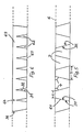
- FIG. 8 Such a composite material for the wall of the tubular segment body is shown in FIG. 8.
- meshes 71 between the resin-permeated and / or coated fibers 70 remain free of resin, so that they form a perforated screen structure that is particularly suitable for the cutlery.
- Pipe segment body with the fiber fabric / resin composite material are still impact and break resistant and moisture-repellent. Wall thicknesses of only a few millimeters can advantageously be formed with the fabric / resin composite material. This leads to a relatively low weight of the segment body or the core body.
- core bodies with straight and / or curved sections can be formed.
- core bodies according to the invention can also be assembled from a combination of differently cut cut parts.
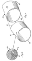
- 4 shows a cut part segment body 23 with circular ring composite surfaces 33 cut at right angles to the outer surface 26. It may also be expedient to use cut part segment bodies which are cut at right angles on one end face and at an oblique angle on the other end face.
- the material strands or the cut part segment bodies can have a wide variety of cross-sectional shapes. It is particularly advantageous to form an arcuate and flattened cross-sectional shape as shown in FIGS. 9A and 9B.
- the core body comprises a flat support side and a side that is arched for fitting with jewelry parts.
- segment body 2 which have a symmetrical trapezoidal shape in the horizontal section.
- the cut part segment bodies 2 are then joined together with their smooth, blunt composite surfaces 31 and 32 to form a closed ring according to FIG. 1 or 9A / 9B.
- the elongated production strand 6 can be guided evenly transversely to an oscillating saw, so that segment bodies 2 of the same size and shape can be obtained in a simple manner.
- 67 wedge-shaped elements are cut out of a strand (FIG. 6), so that separate segment bodies 2 are obtained by means of angular recesses 62, which remain integrally connected at composite surface corner regions 64 via a remaining strand backbone part 63 .
- the recesses 62 cut perpendicular to a horizontal plane of the strand 67 are provided at the same intervals and the same size.
- the cut surfaces form smooth, blunt composite surfaces 31 and 32 of the tooth-like segment body 2 on the backbone part 63.
- the cut strand 67 is bent in a circular shape along the backbone part 63 until the composite surfaces 31, 32 lie against one another in the butt joint.
- the backbone part 63 is closed with adjoining cut surfaces 36.
- the strand 6 consists of a flexible or flexible material, such as e.g. Corrugated cardboard, and / or the backbone part 63 is made sufficiently thin, narrow or web-like.
- the strand or the segment body 2 consist of covered corrugated cardboard layers.
- the cut part segment bodies can be cut particularly easily from the corrugated cardboard strand.
- the segment bodies are cut parts of a corrugated cardboard strand (FIG. 7).
- a corrugated cardboard strand (FIG. 7). This is obtained by rolling up a sheet of corrugated cardboard 66 covered on one side with a blanket 65 rolled on the outside so that the shafts are aligned with the winding axis.
- the end areas of the layers can be attached to each other with glue, adhesive tape or tack. It is particularly useful to have the corrugations on the uncovered side of the corrugated board to be provided with adhesive dots or adhesive lines during the winding process. This creates a very stable and therefore pressure-resistant inner winding structure after the adhesive has hardened.
- the corrugated cardboard winding can have a circular, but in particular also an arcuate and flattened or oval cross section.
- the diameter of the corrugated cardboard roll is, for example, 100 mm, and the roll has a length of approximately 2,200 mm.
- 20 to 40 segment bodies can be cut from such a strand.
- the corrugated cardboard strand can be wound in the form of a tube or hollow strand, for example with an outer diameter of 100 mm, an inner diameter of 60-90 mm and a length of 2,200 mm (FIG. 7B).
- FIGS. 9A and 9B The formation of vertical stabilization surfaces within a core body ring 1 is shown with reference to FIGS. 9A and 9B. These result from the full-surface application of a glue 8 to the cut composite surfaces 31, 32 of the segment body 2.
- solid disks 80 are formed with a rigidity which is determined by the degree of hardening of the glue.
- the thickness of a disc depends on the amount of glue applied.
- the glue can be applied in the form of a film, so that very thin-walled panes are produced which nevertheless have great rigidity.
- the amount of glue applied also depends on the material used for the strand or the segment body.
- corrugated cardboard as a strand material is very advantageous, since only a very small amount of glue is required on the corrugated cardboard cut composite surfaces.
- corrugated cardboard is an environmentally friendly, easy to cut and inexpensive material with which the strand in the form of a wrap can be easily produced.
- the inherently soft corrugated cardboard material ensures that the core body can be easily fitted with needles or the like Disks 80 are joined together, a skeleton is formed, which gives the core body 1 rigidity, great stability and compressive strength.
- FIG. 9A shows full-area disks 80 of a solid core body 1
- FIG. 9B shows the lattice structure of a hollow ring 1 with annular disks 80.
Landscapes
- Life Sciences & Earth Sciences (AREA)
- Environmental Sciences (AREA)
- Laminated Bodies (AREA)
- Making Paper Articles (AREA)
Priority Applications (1)
| Application Number | Priority Date | Filing Date | Title |
|---|---|---|---|
| AT89102712T ATE92245T1 (de) | 1988-02-20 | 1989-02-17 | Kernkoerper fuer schmuck-, pflanzen-, trauergebinde od. dgl. |
Applications Claiming Priority (2)
| Application Number | Priority Date | Filing Date | Title |
|---|---|---|---|
| EP88730039 | 1988-02-20 | ||
| EP88730039 | 1988-02-20 |
Publications (2)
| Publication Number | Publication Date |
|---|---|
| EP0330079A1 true EP0330079A1 (fr) | 1989-08-30 |
| EP0330079B1 EP0330079B1 (fr) | 1993-08-04 |
Family
ID=8200545
Family Applications (1)
| Application Number | Title | Priority Date | Filing Date |
|---|---|---|---|
| EP19890102712 Expired - Lifetime EP0330079B1 (fr) | 1988-02-20 | 1989-02-17 | Noyau pour couronne de décoration, de plantes de deuil ou analogue |
Country Status (2)
| Country | Link |
|---|---|
| EP (1) | EP0330079B1 (fr) |
| DE (2) | DE8916080U1 (fr) |
Families Citing this family (3)
| Publication number | Priority date | Publication date | Assignee | Title |
|---|---|---|---|---|
| DE9308292U1 (de) * | 1992-11-24 | 1993-10-14 | Indlekofer, Manfred, 79761 Waldshut-Tiengen | Unterbaureif für Kränze |
| DE4411915C2 (de) * | 1994-04-07 | 1996-10-31 | Josef Kempa | Gesteckkörper für Grab- und Tischgestecke |
| DE202008000516U1 (de) * | 2008-01-11 | 2009-05-20 | Schneider, Dieter | Gesteckrohling |
Citations (1)
| Publication number | Priority date | Publication date | Assignee | Title |
|---|---|---|---|---|
| FR2394993A1 (fr) * | 1977-06-21 | 1979-01-19 | Gautier Pierre | Moules a deuil |
-
1989
- 1989-02-17 DE DE8916080U patent/DE8916080U1/de not_active Expired - Lifetime
- 1989-02-17 DE DE8989102712T patent/DE58905075D1/de not_active Expired - Fee Related
- 1989-02-17 EP EP19890102712 patent/EP0330079B1/fr not_active Expired - Lifetime
Patent Citations (1)
| Publication number | Priority date | Publication date | Assignee | Title |
|---|---|---|---|---|
| FR2394993A1 (fr) * | 1977-06-21 | 1979-01-19 | Gautier Pierre | Moules a deuil |
Also Published As
| Publication number | Publication date |
|---|---|
| DE8916080U1 (de) | 1993-06-03 |
| DE58905075D1 (de) | 1993-09-09 |
| EP0330079B1 (fr) | 1993-08-04 |
Similar Documents
| Publication | Publication Date | Title |
|---|---|---|
| DE2112441C2 (de) | Verfahren zur Herstellung eines Kunststoffilaments | |
| DE4103426A1 (de) | Flache, rechteckige verbundmaterialisolierung | |
| EP0440760A1 (fr) | Element de construction tridimensionnel. | |
| DE2050717B2 (de) | Unterirdischer Speichertank und Verfahren zu seiner Herstellung | |
| DE102008010610B4 (de) | Wärmeisolierende Umkleidung | |
| EP0330079B1 (fr) | Noyau pour couronne de décoration, de plantes de deuil ou analogue | |
| EP0202518B1 (fr) | Elément de couverture de toit de paille en matière plastique et procédé pour la pose de celui-ci sur des surfaces de toit | |
| CH446945A (de) | Verstärkte Schleifscheibe | |
| DE9101996U1 (de) | Schalung für Betonstützen | |
| DE3510294C1 (de) | Gabelbaum fuer Segelbretter | |
| DE69718287T2 (de) | Mähfaden für busch- und kantentrimmer | |
| DE3805614A1 (de) | Ummantelung eines kern- oder formkoerpers fuer schmuck-, pflanzen-, trauergebinde od. dgl. | |
| DE69800555T2 (de) | Fadenschneider für Busch- und Kantentrimmer | |
| EP0433843A2 (fr) | Arbre creux et procédé pour sa fabrication | |
| DE2945128C2 (de) | Präparierte Blattpflanze | |
| CH683932A5 (de) | Lagerfugenbewehrung. | |
| EP0327953A2 (fr) | Bande en vannerie et procédé pour sa fabrication | |
| DE8705206U1 (de) | Mit spitzförmigen Gegenständen besteckbarer Formkörper | |
| DE102023118548A1 (de) | Konstruktionselement und Verfahren zur Herstellung des Konstruktionselements | |
| DE3231000C2 (de) | Betonring zur Bildung von Mauern und seine Verwendung | |
| DE2904698A1 (de) | Rotationsstanze mit schraubenfoermig verspanntem widerlager | |
| DE1434126C (de) | Wellenförmig oder ähnlich profiliertes Bauelement aus Holz 4nm Witschmg, Walter, Metmtz (Oster reich) | |
| DE8802354U1 (de) | Kernkörper für Schmuck-, Pflanzen-, Trauergebinde od. dgl. | |
| DE29719758U1 (de) | Verbundmaterial | |
| DE19857606A1 (de) | Verfahren zur Herstellung von Fachwerken |
Legal Events
| Date | Code | Title | Description |
|---|---|---|---|
| PUAI | Public reference made under article 153(3) epc to a published international application that has entered the european phase |
Free format text: ORIGINAL CODE: 0009012 |
|
| AK | Designated contracting states |
Kind code of ref document: A1 Designated state(s): AT BE CH DE FR GB IT LI NL |
|
| 17P | Request for examination filed |
Effective date: 19890713 |
|
| 17Q | First examination report despatched |
Effective date: 19901019 |
|
| GRAA | (expected) grant |
Free format text: ORIGINAL CODE: 0009210 |
|
| AK | Designated contracting states |
Kind code of ref document: B1 Designated state(s): AT BE CH DE FR GB IT LI NL |
|
| PG25 | Lapsed in a contracting state [announced via postgrant information from national office to epo] |
Ref country code: IT Free format text: LAPSE BECAUSE OF FAILURE TO SUBMIT A TRANSLATION OF THE DESCRIPTION OR TO PAY THE FEE WITHIN THE PRE;WARNING: LAPSES OF ITALIAN PATENTS WITH EFFECTIVE DATE BEFORE 2007 MAY HAVE OCCURRED AT ANY TIME BEFORE 2007. THE CORRECT EFFECTIVE DATE MAY BE DIFFERENT FROM THE ONE RECORDED.SCRIBED TIME-LIMIT Effective date: 19930804 Ref country code: BE Effective date: 19930804 Ref country code: FR Effective date: 19930804 Ref country code: GB Effective date: 19930804 Ref country code: NL Effective date: 19930804 |
|
| REF | Corresponds to: |
Ref document number: 92245 Country of ref document: AT Date of ref document: 19930815 Kind code of ref document: T |
|
| REF | Corresponds to: |
Ref document number: 58905075 Country of ref document: DE Date of ref document: 19930909 |
|
| EN | Fr: translation not filed | ||
| PGFP | Annual fee paid to national office [announced via postgrant information from national office to epo] |
Ref country code: CH Payment date: 19940107 Year of fee payment: 6 |
|
| NLV1 | Nl: lapsed or annulled due to failure to fulfill the requirements of art. 29p and 29m of the patents act | ||
| GBV | Gb: ep patent (uk) treated as always having been void in accordance with gb section 77(7)/1977 [no translation filed] |
Effective date: 19930804 |
|
| PLBE | No opposition filed within time limit |
Free format text: ORIGINAL CODE: 0009261 |
|
| STAA | Information on the status of an ep patent application or granted ep patent |
Free format text: STATUS: NO OPPOSITION FILED WITHIN TIME LIMIT |
|
| 26N | No opposition filed | ||
| PG25 | Lapsed in a contracting state [announced via postgrant information from national office to epo] |
Ref country code: LI Effective date: 19950228 Ref country code: CH Effective date: 19950228 |
|
| PGFP | Annual fee paid to national office [announced via postgrant information from national office to epo] |
Ref country code: AT Payment date: 19980226 Year of fee payment: 10 |
|
| PG25 | Lapsed in a contracting state [announced via postgrant information from national office to epo] |
Ref country code: AT Free format text: LAPSE BECAUSE OF NON-PAYMENT OF DUE FEES Effective date: 19990217 |
|
| PGFP | Annual fee paid to national office [announced via postgrant information from national office to epo] |
Ref country code: DE Payment date: 20030227 Year of fee payment: 15 |
|
| PG25 | Lapsed in a contracting state [announced via postgrant information from national office to epo] |
Ref country code: DE Free format text: LAPSE BECAUSE OF NON-PAYMENT OF DUE FEES Effective date: 20040901 |