EP0330082A2 - Dispositif support de câble - Google Patents
Dispositif support de câble Download PDFInfo
- Publication number
- EP0330082A2 EP0330082A2 EP89102721A EP89102721A EP0330082A2 EP 0330082 A2 EP0330082 A2 EP 0330082A2 EP 89102721 A EP89102721 A EP 89102721A EP 89102721 A EP89102721 A EP 89102721A EP 0330082 A2 EP0330082 A2 EP 0330082A2
- Authority
- EP
- European Patent Office
- Prior art keywords
- cable
- sheath
- receiving device
- adhesive layer
- cable duct
- Prior art date
- Legal status (The legal status is an assumption and is not a legal conclusion. Google has not performed a legal analysis and makes no representation as to the accuracy of the status listed.)
- Withdrawn
Links
Images
Classifications
-
- H—ELECTRICITY
- H02—GENERATION; CONVERSION OR DISTRIBUTION OF ELECTRIC POWER
- H02G—INSTALLATION OF ELECTRIC CABLES OR LINES, OR OF COMBINED OPTICAL AND ELECTRIC CABLES OR LINES
- H02G3/00—Installations of electric cables or lines or protective tubing therefor in or on buildings, equivalent structures or vehicles
- H02G3/02—Details
- H02G3/04—Protective tubing or conduits, e.g. cable ladders or cable troughs
- H02G3/0406—Details thereof
-
- H—ELECTRICITY
- H02—GENERATION; CONVERSION OR DISTRIBUTION OF ELECTRIC POWER
- H02G—INSTALLATION OF ELECTRIC CABLES OR LINES, OR OF COMBINED OPTICAL AND ELECTRIC CABLES OR LINES
- H02G3/00—Installations of electric cables or lines or protective tubing therefor in or on buildings, equivalent structures or vehicles
- H02G3/02—Details
- H02G3/04—Protective tubing or conduits, e.g. cable ladders or cable troughs
- H02G3/0437—Channels
Definitions
- the invention relates to a cable receiving device according to the preamble of patent claim 1.
- Flexible cable sleeves are also known, on the longitudinal edges of which the closure rails of a zipper are arranged.
- Such flexible cable sleeves can have a metal coating on their inside, which acts as an RF shield.
- a disadvantage of such prefabricated cable sleeves is that sleeves of a suitable width must be kept available for all diameters of the cable bundle. The sleeves cannot be cut to size because one of the zipper rails would then be cut off.
- Another disadvantage of such cable sleeves is that they have to be opened from one end. If access to the cable bundle is desired at the other end, the zipper must be pulled along its entire length.
- the known rigid cable ducts are used for the protected accommodation of cables in buildings, vehicles, aircraft, ships and. Like .. When the cable bundle or part of it leaves the cable duct, it is completely unprotected and the individual cables of the bundle are not secured against displacement and displacement.
- the invention has for its object to provide a cable receiving device of the type specified in the preamble of claim 1, in which several cables are electrically shielded and mechanically protected.
- a flexible sheathing which can be placed around the cable bundle and whose edge regions can be connected by an adhesive layer.
- the flexible covering has an RF shield, preferably in the form of a metal coating. It keeps the cables running inside the cable duct tightly enclosed and protects these cables against external electrical or electromagnetic influences. In many cases it is possible to use unshielded cables and to provide them with the shielding sheath in the cable duct.
- the sheath in the cable duct It is particularly simple to apply the sheath in the cable duct.
- the casing is only placed in the cable duct. Then the cables are inserted and finally the covering is closed by superimposing its edge areas. If necessary, the covering is accessible at any point by merely pulling apart the edge areas at this point.
- the covering can also be carried over the end of the cable duct with the cable bundle protruding from the cable duct.
- the cable duct does not necessarily have to be straight, but it can also have corner pieces, T pieces and branching pieces.
- the fixation of the sheath in the cable duct is facilitated.
- the covering is fixed with the further adhesive layer to a wall of the cable duct, so that it cannot move when the cable is inserted and when the covering is closed.
- a preferred embodiment of the casing is specified in claim 3.
- a grounding wire and the first adhesive layer run adjacent to one another along the one longitudinal edge of the sheathing. If the sheathing is closed by overlapping its edge areas, then the grounding wire lies against the HF shielding of the upper tab from below.
- the adhesive layer is located on the lower tab and holds the upper tab from there. It is particularly advantageous that the casing can be cut to size by the user in accordance with the width or the inner circumference of the cable duct used, by cutting off a correspondingly wide strip from the longitudinal edge facing away from the grounding wire.
- the functional parts, namely the grounding wire and the first adhesive layer run along one longitudinal edge, while the other longitudinal edge is free of functional parts and can be cut to any desired size.
- the sheath can easily be adapted to the shape and size of the cable bundle. It is simple and inexpensive to manufacture and its assembly can be carried out by inexperienced forces without difficulty.
- a filling material e.g. a foam. This filling material presses against the mutually adhering, overlapping edge regions of the casing and thus helps to ensure the closed state of the casing.
- the covering can be used in connection with various types of cable ducts, for example with open cable ducts or cable ducts that can be closed by a cover.
- the cable duct preferably has a hinged cover and it can in particular consist of a one-piece plastic profile in which the hinged cover is connected to the trunk of the cable duct via a film hinge.
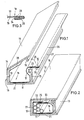
- the receiving device shown has an elongated cable duct 10, which consists of a one-piece profile.
- the fuselage of the cable duct 10 has a bottom wall 11 and side walls 12, 13 protruding therefrom at right angles.
- the lid 15 is connected to the side wall 12 via a film hinge 14.
- the flexible sheath 18 is inserted into the cable duct 10.
- This is a film strip 19 made of plastic film one side is provided with an RF shield in the form of a metal coating 20.
- the metal coating forms the inside of the casing.
- the envelope 18 is provided on the outside in the central region of its width with a longitudinal adhesive layer 21 which consists of a double-sided adhesive tape.
- the adhesive layer 21 is glued to the bottom 11 of the cable duct 10, the lateral regions of the covering lying against the side walls or the cover 15 and the one edge according to FIG. 1 being folded out over the side wall 13. In this state, the cables can be inserted into the sheath 18.
- the longitudinal adhesive layer 23 On the outside of the casing 18, in the vicinity of the edge 22, there is the longitudinal adhesive layer 23 in the form of a strip of double-sided adhesive tape.
- the edge according to FIG. 3 is folded over at the edge 22, so that the HF shield 20 is directed outwards in the folded over edge strip 24.
- the longitudinal grounding wire 25 made of metal wire mesh is sewn onto the outside of the edge strip 24, that is to say to the HF shielding 20.
- the seam is designated by 26 in FIG.
- the edge region carrying the grounding strands 25 is folded over the cable bundle 27 in the direction of arrow 28 of FIG. 1, so that the grounding strands 25 and the adhesive layer 23 follow are directed above. Then the opposite edge 29 is pressed from above against the adhesive layer 23, whereby it sticks to the adhesive layer. The immediate vicinity of the adhesive layer 23 and the grounding wire 25 ensures that the RF shield 20 of the edge region 29 is held firmly against the grounding wire 25.
Landscapes
- Engineering & Computer Science (AREA)
- Architecture (AREA)
- Civil Engineering (AREA)
- Structural Engineering (AREA)
- Details Of Indoor Wiring (AREA)
- Installation Of Indoor Wiring (AREA)
Applications Claiming Priority (2)
| Application Number | Priority Date | Filing Date | Title |
|---|---|---|---|
| DE3805330 | 1988-02-20 | ||
| DE19883805330 DE3805330C1 (fr) | 1988-02-20 | 1988-02-20 |
Publications (2)
| Publication Number | Publication Date |
|---|---|
| EP0330082A2 true EP0330082A2 (fr) | 1989-08-30 |
| EP0330082A3 EP0330082A3 (fr) | 1991-03-20 |
Family
ID=6347810
Family Applications (1)
| Application Number | Title | Priority Date | Filing Date |
|---|---|---|---|
| EP19890102721 Withdrawn EP0330082A3 (fr) | 1988-02-20 | 1989-02-17 | Dispositif support de câble |
Country Status (3)
| Country | Link |
|---|---|
| EP (1) | EP0330082A3 (fr) |
| JP (1) | JPH01252111A (fr) |
| DE (1) | DE3805330C1 (fr) |
Cited By (7)
| Publication number | Priority date | Publication date | Assignee | Title |
|---|---|---|---|---|
| EP0536541A3 (fr) * | 1991-10-05 | 1993-04-21 | BESMA BESCHICHTUNGSMASSEN GmbH | Feuille déformable pour accrocher sur un support et protéger contre les rayonnements ou isoler des parties électriquement conductrices |
| GB2274746A (en) * | 1993-01-18 | 1994-08-03 | Powercentre Holdings Ltd | Shielded conduit |
| EP0637864A1 (fr) * | 1992-01-17 | 1995-02-08 | The Wiremold Company | Assemblage de chemin de câbles |
| FR2756113A1 (fr) * | 1996-11-21 | 1998-05-22 | France Etat | Ensemble modulaire avec protection radioelectrique pour le cheminement de cables |
| AT503205B1 (de) * | 2006-01-18 | 2007-11-15 | Anton Dipl Ing Zahradnik | Hüllen für kabelführungen |
| WO2009077116A1 (fr) * | 2007-12-14 | 2009-06-25 | Anton Zahradnik | Inserts profilés du genre agrafes pour éléments de guidage de câbles |
| EP3244501A1 (fr) * | 2016-05-13 | 2017-11-15 | Maria Iciar Zublezu Llona | Canal pour la protection et l'isolation des câbles d'alimentations électriques |
Families Citing this family (9)
| Publication number | Priority date | Publication date | Assignee | Title |
|---|---|---|---|---|
| DE4104969C1 (en) * | 1991-02-19 | 1992-04-02 | Mercedes-Benz Aktiengesellschaft, 7000 Stuttgart, De | Protective tubing for cable - is U=shaped with weakened wall section to allow pivoting for easier installation in motor vehicle |
| DE4108980A1 (de) * | 1991-03-19 | 1992-09-24 | Siemens Ag | Einteiliger kunststoffkanal zur leitungsfuehrung, verdrahtung und/oder geraetehalterung, und verfahren zu dessen herstellung |
| DE9103649U1 (de) * | 1991-03-25 | 1991-06-27 | REHAU AG + Co, 8673 Rehau | Befestigungselement zum Festlegen von Kabelkanälen an Wandbereichen |
| DE9318937U1 (de) * | 1993-12-09 | 1994-03-03 | Trw United-Carr Gmbh & Co Kg, 67677 Enkenbach-Alsenborn | Führungskanal |
| DE19532392C2 (de) * | 1995-09-02 | 2003-07-03 | Bosch Gmbh Robert | Kabelkanalprofil zur Verlegung von Installationsleitungen oder dergleichen |
| JP3391985B2 (ja) * | 1996-06-19 | 2003-03-31 | 星和電機株式会社 | 電線保護カバー |
| DE29702669U1 (de) * | 1997-02-15 | 1997-04-03 | Rehau Ag + Co, 95111 Rehau | Installationskanal |
| JP4978507B2 (ja) * | 2008-02-20 | 2012-07-18 | 三菱電機株式会社 | 車両用制御装置 |
| KR101657478B1 (ko) * | 2016-05-02 | 2016-09-21 | 주식회사 행림종합 건축사사무소 | 개선된 구조의 전기케이블 트레이 및 그 설치시공법 |
Family Cites Families (7)
| Publication number | Priority date | Publication date | Assignee | Title |
|---|---|---|---|---|
| US3357455A (en) * | 1966-06-13 | 1967-12-12 | Walter A Plummer | Multiple channel jacketing with attached mounting strip |
| DE1615984B1 (de) * | 1967-06-26 | 1971-08-26 | Danzer Metal Works Co | Metallische Kabelrinne fuer Nachrichtenkabel |
| US3582532A (en) * | 1969-11-26 | 1971-06-01 | Walter A Plummer | Shielded jacket assembly for flat cables |
| SE420552B (sv) * | 1979-05-03 | 1981-10-12 | Ericsson Telefon Ab L M | Bandformig anordning for bildande av ett rorformigt teck- och skyddsholje |
| JPS58502031A (ja) * | 1981-11-20 | 1983-11-24 | ポラツク ロナルド エム | 電気コ−ドホルダ及びカバ− |
| US4734542A (en) * | 1985-12-27 | 1988-03-29 | The Zippertubing Company | Flat tubular jacket |
| DE8710777U1 (de) * | 1987-08-06 | 1987-09-24 | OBO Bettermann oHG, 5750 Menden | Faltbarer Kabelkanal |
-
1988
- 1988-02-20 DE DE19883805330 patent/DE3805330C1/de not_active Expired
-
1989
- 1989-02-17 EP EP19890102721 patent/EP0330082A3/fr not_active Withdrawn
- 1989-02-20 JP JP1040139A patent/JPH01252111A/ja active Pending
Cited By (9)
| Publication number | Priority date | Publication date | Assignee | Title |
|---|---|---|---|---|
| EP0536541A3 (fr) * | 1991-10-05 | 1993-04-21 | BESMA BESCHICHTUNGSMASSEN GmbH | Feuille déformable pour accrocher sur un support et protéger contre les rayonnements ou isoler des parties électriquement conductrices |
| EP0637864A1 (fr) * | 1992-01-17 | 1995-02-08 | The Wiremold Company | Assemblage de chemin de câbles |
| GB2274746A (en) * | 1993-01-18 | 1994-08-03 | Powercentre Holdings Ltd | Shielded conduit |
| FR2756113A1 (fr) * | 1996-11-21 | 1998-05-22 | France Etat | Ensemble modulaire avec protection radioelectrique pour le cheminement de cables |
| EP0844713A1 (fr) * | 1996-11-21 | 1998-05-27 | Etat-Francais représenté par le Délégué Général pour L'Armement | Ensemble modulaire pour support de câbles avec protection radioélectrique |
| AT503205B1 (de) * | 2006-01-18 | 2007-11-15 | Anton Dipl Ing Zahradnik | Hüllen für kabelführungen |
| US7741561B2 (en) | 2006-01-18 | 2010-06-22 | Anton Zahradnik | Electrosmog shielding for cable conduit |
| WO2009077116A1 (fr) * | 2007-12-14 | 2009-06-25 | Anton Zahradnik | Inserts profilés du genre agrafes pour éléments de guidage de câbles |
| EP3244501A1 (fr) * | 2016-05-13 | 2017-11-15 | Maria Iciar Zublezu Llona | Canal pour la protection et l'isolation des câbles d'alimentations électriques |
Also Published As
| Publication number | Publication date |
|---|---|
| EP0330082A3 (fr) | 1991-03-20 |
| JPH01252111A (ja) | 1989-10-06 |
| DE3805330C1 (fr) | 1989-08-17 |
Similar Documents
| Publication | Publication Date | Title |
|---|---|---|
| DE3805330C1 (fr) | ||
| DE3840880C2 (de) | Leitende Kabelhülle | |
| DE69609447T2 (de) | Kabelspleissumhüllung | |
| DE69609885T2 (de) | Wärmeschrumpfbare Abschirm-Hülse und Verfahren zu ihrer Herstellung | |
| DE3640226A1 (de) | Kunststoff-schutzrohranordnung fuer leitungen | |
| DE1690540C3 (de) | Umhüllung für elektrische Leiter, Kabel od. dgl | |
| DE693929C (de) | Dehnbare elektrische Leitung | |
| DE1690229C3 (de) | Elektrisches Kabelabschirmband | |
| DE3504910A1 (de) | Wiederverschliessbarer abschirmmantel fuer elektrische leiter | |
| EP0155393B1 (fr) | Barrage à fréquence pour fermetures de boîtiers ou de portes | |
| DE7731455U1 (de) | Verbindungsstück | |
| DE2301771A1 (de) | Kabel mit aufreissbarem kabelmantel | |
| DE69416112T2 (de) | Abschirmvorrichtung zwischen mehreren abgeschirmten Kabeln und einem Verbinder | |
| DE102022106503A1 (de) | Fahrzeugdachdeckel mit einer Kabelverbindung | |
| DE10158835A1 (de) | Elektrokabel | |
| DE1247435B (de) | Schutz-Umhuellung zur Aufnahme von elektrischen Leitern | |
| DE2300986A1 (de) | Kabel od. dgl | |
| DE19711094B4 (de) | Kabelsammler | |
| DE3112526C2 (de) | Einrichtung zum Kontaktieren eines Kabelschirms | |
| DE4013886A1 (de) | Gehaeuse mit hf-dichter kabeldurchfuehrung | |
| DE3336701C2 (fr) | ||
| DE7034979U (de) | Elektrischer leiter. | |
| DE1953655U (de) | Schutz-umhuellung zur aufnahme von elektrischen leitern. | |
| DE4217906C2 (de) | Kabeleinführungstülle zum Einführen eines Kabels in ein Gehäuse oder dergleichen | |
| EP0410101B1 (fr) | Connection terminal pour au moins deux câbles blindés |
Legal Events
| Date | Code | Title | Description |
|---|---|---|---|
| PUAI | Public reference made under article 153(3) epc to a published international application that has entered the european phase |
Free format text: ORIGINAL CODE: 0009012 |
|
| AK | Designated contracting states |
Kind code of ref document: A2 Designated state(s): AT BE CH DE ES FR GB IT LI NL SE |
|
| PUAL | Search report despatched |
Free format text: ORIGINAL CODE: 0009013 |
|
| AK | Designated contracting states |
Kind code of ref document: A3 Designated state(s): AT BE CH DE ES FR GB IT LI NL SE |
|
| STAA | Information on the status of an ep patent application or granted ep patent |
Free format text: STATUS: THE APPLICATION HAS BEEN WITHDRAWN |
|
| 18W | Application withdrawn |
Withdrawal date: 19910920 |