EP0330802A1 - Système de visée pour armes à feu à main - Google Patents
Système de visée pour armes à feu à main Download PDFInfo
- Publication number
- EP0330802A1 EP0330802A1 EP88810122A EP88810122A EP0330802A1 EP 0330802 A1 EP0330802 A1 EP 0330802A1 EP 88810122 A EP88810122 A EP 88810122A EP 88810122 A EP88810122 A EP 88810122A EP 0330802 A1 EP0330802 A1 EP 0330802A1
- Authority
- EP
- European Patent Office
- Prior art keywords
- housing
- optics
- weapon
- sighting
- screw
- Prior art date
- Legal status (The legal status is an assumption and is not a legal conclusion. Google has not performed a legal analysis and makes no representation as to the accuracy of the status listed.)
- Ceased
Links
- 230000001681 protective effect Effects 0.000 claims abstract description 29
- 230000003287 optical effect Effects 0.000 claims description 2
- 230000011514 reflex Effects 0.000 description 2
- 229910000760 Hardened steel Inorganic materials 0.000 description 1
- XAGFODPZIPBFFR-UHFFFAOYSA-N aluminium Chemical compound [Al] XAGFODPZIPBFFR-UHFFFAOYSA-N 0.000 description 1
- 229910052782 aluminium Inorganic materials 0.000 description 1
- 238000010276 construction Methods 0.000 description 1
- 230000003014 reinforcing effect Effects 0.000 description 1
- 239000013585 weight reducing agent Substances 0.000 description 1
Images

Classifications
-
- F—MECHANICAL ENGINEERING; LIGHTING; HEATING; WEAPONS; BLASTING
- F41—WEAPONS
- F41G—WEAPON SIGHTS; AIMING
- F41G1/00—Sighting devices
- F41G1/06—Rearsights
- F41G1/16—Adjusting mechanisms therefor; Mountings therefor
-
- F—MECHANICAL ENGINEERING; LIGHTING; HEATING; WEAPONS; BLASTING
- F41—WEAPONS
- F41G—WEAPON SIGHTS; AIMING
- F41G1/00—Sighting devices
- F41G1/06—Rearsights
- F41G1/065—Protection means therefor
Definitions
- a handgun according to the preamble of claim 1 is known from DE-OS 2 023 270.
- the sight optics of this weapon are held in a bearing block attached to the top of the weapon housing.
- the visor optics are protected by a protective housing that forms a carrying handle.
- the protective housing can be opened so that the mounting of the bearing block and thus the sight optics on the top of the weapon housing and the adjustment of the sight optics is possible.
- the protective optics are well protected with the protective housing, the weapon becomes considerably heavier and the adjustment of the visor optics is very cumbersome.
- the invention has for its object to develop a handgun according to the preamble of claim 1 so that the additional weight can be reduced by the protective housing, and that simple adjustment is possible. This object is achieved by the characterizing features of claim 1.
- the protective housing is permanently connected to the weapon housing, e.g. is welded on, it can be built much lighter than the known protective housing.
- the attachment of the visor optics and the adjustment device can be made very simple and space-saving. This makes it possible to reduce the overall height, which not only means a further weight reduction, but also has the advantage of a low line of sight.
- the sight optics in the embodiment according to the invention are therefore not attached to the weapon as is known from the prior art (e.g. DE-OS 3 136 946, US Pat. No. 3 867 764, EP-A 103 510), but are integrated into the weapon.
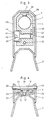
- a protective housing 3 enveloping the target optics 1 is welded to the weapon housing 2.
- the target optics 1 is designed as a reflex sight.
- a circular cylindrical opening 4 in the aluminum housing 5 of the sighting optics 1 gives an unenlarged picture of the target area around the axis 6 of the sighting optics 1.
- a target mark is faded in by a full mirror 7 and a semitransparent mirror 8, which target mark head 9 generates with ambient light and is focused by a lens system 10.
- Such a reflex sight is known per se.
- the housing 5 of the sight optics 1 is centered at the front with a bolt 15 relative to the weapon housing 2.
- the bolt 15 penetrates a bore 16 of the housing 5 of the sighting optics 1 and is guided in a bore 17 of the weapon housing 2. It has a shoulder 18 at the top, which bears against a pin 20 which is transversely inserted through bores 19 of the protective housing 3 and presses the housing 5 of the sighting optics 1 against the weapon housing 2 with a plate spring 21.
- a hardened steel ball 22 is embedded in the housing 5 on both sides of the spring 21, which rests on a U-shaped reinforcing plate 23 that is spot-welded to the weapon housing 2 and the protective housing 3.
- a height adjustment screw 28 with a toothed adjustment head 29 is screwed into the housing 5 perpendicular to the axis 6.
- the lower end 30 of the screw 28 is crowned and rests on a support plate 31 which is spot-welded to the weapon housing 2.
- a ball 33 loaded by a spring 32 presses radially against the toothing of the head 29, so that the height adjustment is insensitive to vibrations.
- a leaf spring 34 is clamped between the upper wall 35 of the protective housing 3 and the upper side of the housing 5 of the visor optics 1. Their two ends are bent over and sit in bores 36 of the housing 5. The spring 34 presses the spherical end 30 of the adjusting screw 28 against the plate 31 and eliminates the thread play of the adjusting screw 28.
- a side adjustment screw 40 with a toothed head 41 is screwed into the housing 5 of the sight optics 1 transversely to the screw 28 and to the axis 6.
- the head 41 has a screwdriver slot 42, projects beyond the housing 5 of the visor optics 1 and lies against the left side wall 43 of the protective housing 3.
- the side wall 43 has a bore 44 of smaller diameter than the diameter of the head 41.
- Another leaf spring 46 is clamped between the opposite side wall 45 of the protective housing 3 and the housing 5, the two free ends of which bent and positioned in blind holes 47 in the housing 5.
- the head 41 is thus pressed against the wall 43 and the thread play of the screw 40 is canceled.
- a spring-loaded ball not shown, for securing the side adjustment.
Landscapes
- Physics & Mathematics (AREA)
- Optics & Photonics (AREA)
- Engineering & Computer Science (AREA)
- General Engineering & Computer Science (AREA)
- Telescopes (AREA)
- Aiming, Guidance, Guns With A Light Source, Armor, Camouflage, And Targets (AREA)
Applications Claiming Priority (1)
| Application Number | Priority Date | Filing Date | Title |
|---|---|---|---|
| CH81386A CH668831A5 (de) | 1986-02-28 | 1986-02-28 | Handfeuerwaffe mit einer visiereinrichtung. |
Publications (1)
| Publication Number | Publication Date |
|---|---|
| EP0330802A1 true EP0330802A1 (fr) | 1989-09-06 |
Family
ID=4195784
Family Applications (1)
| Application Number | Title | Priority Date | Filing Date |
|---|---|---|---|
| EP88810122A Ceased EP0330802A1 (fr) | 1986-02-28 | 1988-02-29 | Système de visée pour armes à feu à main |
Country Status (2)
| Country | Link |
|---|---|
| EP (1) | EP0330802A1 (fr) |
| CH (1) | CH668831A5 (fr) |
Families Citing this family (1)
| Publication number | Priority date | Publication date | Assignee | Title |
|---|---|---|---|---|
| US5274941A (en) * | 1992-05-08 | 1994-01-04 | Warren Moore | Selectively adjustable firearm scope mount |
Citations (2)
| Publication number | Priority date | Publication date | Assignee | Title |
|---|---|---|---|---|
| DE2023270A1 (de) * | 1970-05-13 | 1971-11-18 | Heckler & Koch Gmbh, 7238 Oberndorf | Handfeuerwaffe mit Tragegriff |
| DE3326853A1 (de) * | 1983-03-10 | 1984-09-13 | Carl Walther Gmbh, 7900 Ulm | Diopter-zielvorrichtung |
-
1986
- 1986-02-28 CH CH81386A patent/CH668831A5/de not_active IP Right Cessation
-
1988
- 1988-02-29 EP EP88810122A patent/EP0330802A1/fr not_active Ceased
Patent Citations (2)
| Publication number | Priority date | Publication date | Assignee | Title |
|---|---|---|---|---|
| DE2023270A1 (de) * | 1970-05-13 | 1971-11-18 | Heckler & Koch Gmbh, 7238 Oberndorf | Handfeuerwaffe mit Tragegriff |
| DE3326853A1 (de) * | 1983-03-10 | 1984-09-13 | Carl Walther Gmbh, 7900 Ulm | Diopter-zielvorrichtung |
Also Published As
| Publication number | Publication date |
|---|---|
| CH668831A5 (de) | 1989-01-31 |
Similar Documents
| Publication | Publication Date | Title |
|---|---|---|
| DE3522027C2 (fr) | ||
| EP0565939B1 (fr) | Dispositif pour ajuster une visée | |
| DE69427863T2 (de) | Weitwinkel-reflexvisier | |
| DE4339397C2 (de) | Zielfernrohr | |
| DE3743092C2 (de) | Gewehr | |
| DE19742248A1 (de) | Verbesserungen an bzw. bezüglich von Feuerwaffen | |
| DE3801037A1 (de) | Diopter fuer ein sportgewehr | |
| EP0330802A1 (fr) | Système de visée pour armes à feu à main | |
| DE3416696A1 (de) | Visiereinrichtung, insbesondere fuer pistolen | |
| DE9007529U1 (de) | Multikaliber-Schußwaffe | |
| DE3204152C2 (de) | Vorrichtung zur Befestigung eines Zielfernrohres an einer Schußwaffe | |
| EP0080091B1 (fr) | Système de montage de tourillon pour canon à gros calibre | |
| DE102005005232A1 (de) | Montage zur Verbindung von Optiken mit Schusswaffen | |
| DE3834304C1 (en) | Device for adjusting at least one front barrel end of a weapon having at least three barrels | |
| EP0117845A1 (fr) | Dispositif de visée pour armes | |
| AT527650B1 (de) | Zielfernrohrsystem | |
| AT402449B (de) | Verstellbare montagevorrichtung für visiereinrichtungen auf waffen | |
| DE4007530C1 (en) | Telescopic sight for rifle - has front foot with bayonet coupling and rear foot with locking device | |
| EP0157992B1 (fr) | Dispositif de montage des moyens de visée sur une arme portative | |
| DE9409365U1 (de) | Laufbefestigung bei Gewehren wobei der Lauf am Schaft befestigt ist | |
| EP0568086B1 (fr) | Dioptre | |
| DE102014003012B4 (de) | Basis für ein Schnellwechselmontagesystem | |
| DE8904801U1 (de) | Einstecklauf für großkalibrige Schußwaffen | |
| DE9405938U1 (de) | Montagezwischenstückeinrichtungen für Langwaffen | |
| EP0038939A1 (fr) | Dispositif de blocage d'un organe mobile le long d'une droite ou autour d'un axe |
Legal Events
| Date | Code | Title | Description |
|---|---|---|---|
| PUAI | Public reference made under article 153(3) epc to a published international application that has entered the european phase |
Free format text: ORIGINAL CODE: 0009012 |
|
| AK | Designated contracting states |
Kind code of ref document: A1 Designated state(s): AT BE CH DE ES FR GB GR IT LI LU NL SE |
|
| RBV | Designated contracting states (corrected) |
Designated state(s): AT BE DE ES FR GB IT SE |
|
| 17P | Request for examination filed |
Effective date: 19891005 |
|
| 17Q | First examination report despatched |
Effective date: 19911007 |
|
| STAA | Information on the status of an ep patent application or granted ep patent |
Free format text: STATUS: THE APPLICATION HAS BEEN REFUSED |
|
| 18R | Application refused |
Effective date: 19921224 |