EP0330861A2 - Glissoir pour guides de fenêtres de véhicules automobiles - Google Patents
Glissoir pour guides de fenêtres de véhicules automobiles Download PDFInfo
- Publication number
- EP0330861A2 EP0330861A2 EP89102002A EP89102002A EP0330861A2 EP 0330861 A2 EP0330861 A2 EP 0330861A2 EP 89102002 A EP89102002 A EP 89102002A EP 89102002 A EP89102002 A EP 89102002A EP 0330861 A2 EP0330861 A2 EP 0330861A2
- Authority
- EP
- European Patent Office
- Prior art keywords
- section
- slider
- web
- sliding
- guide rail
- Prior art date
- Legal status (The legal status is an assumption and is not a legal conclusion. Google has not performed a legal analysis and makes no representation as to the accuracy of the status listed.)
- Granted
Links
Images

Classifications
-
- B—PERFORMING OPERATIONS; TRANSPORTING
- B60—VEHICLES IN GENERAL
- B60J—WINDOWS, WINDSCREENS, NON-FIXED ROOFS, DOORS, OR SIMILAR DEVICES FOR VEHICLES; REMOVABLE EXTERNAL PROTECTIVE COVERINGS SPECIALLY ADAPTED FOR VEHICLES
- B60J10/00—Sealing arrangements
- B60J10/70—Sealing arrangements specially adapted for windows or windscreens
- B60J10/74—Sealing arrangements specially adapted for windows or windscreens for sliding window panes, e.g. sash guides
- B60J10/79—Sealing arrangements specially adapted for windows or windscreens for sliding window panes, e.g. sash guides for flush-glass windows, i.e. for windows flush with the vehicle body or the window frame
Definitions
- the invention relates to a slide for window guides of motor vehicles according to the preamble of claim 1.
- Such sliders are mostly used to guide window panes which are essentially flush with the surrounding body parts, reducing wind noise and achieving a more favorable drag coefficient.
- the known sliders are usually designed as a rotating body and provided with a threaded bore on their side facing the window pane.
- a screw element is screwed into this threaded hole, which is passed through a corresponding recess in the window pane and is used to fasten the slide on the pane.
- the holding section of the slider that is to say the section that receives the threaded bore
- the web of the slider adjoining the holding section should also not be made too wide, since otherwise a correspondingly wide slot is necessary in the guide rail receiving the slider.
- the result of these two requirements is that the slider is very weak in the transition area from the holding section to the web due to the threaded bore. In order to prevent the slider from breaking in this area, high-strength and therefore expensive steels are used for the slider.
- the invention has for its object to develop a slider according to the preamble of claim 1 so that the use of high-strength steel is avoided with equally good or improved strength of the slider.
- the use of Sliding piece no structural changes in relation to the guide rail or the design of the surrounding components may be necessary.
- the proposed sliders could even be used in the conventional window guides without any changes.
- the proposed slider can expediently be made of a suitable plastic. By using the plastic, it is possible to easily realize the elongated cross section.
- Claim 2 indicates a structural design of the slider, in which the sliding section and the holding section of the slider are of a shape concentric to a common axis and the cross section of the web arranged symmetrically thereto has a longitudinal extent which corresponds approximately to the diameters of these sections.
- Such a slider is very easy to manufacture and can also be installed in two positions that are offset by 180 degrees.
- the web can also be made reinforced on one side in the direction perpendicular to the slot in the guide rail, if the structural conditions allow it there. Such adjustments can be easily implemented if the slide is made of a plastic or metal in an injection or casting process.
- the Invention not only improve the strength property of the slider, but also their guiding properties in the guide rail.
- the sliding portion is essentially cuboid in shape and the longer sides of the cuboid run parallel to the guide rail when the slider is mounted. This creates an enlarged base and a lower tensile / compressive load in the guide.
- the region of the holding section facing the glass pane contains ceramic material.
- the use of ceramic material in the area of the adhesive surface creates a material pairing in which each material has approximately the same coefficient of thermal expansion. Shear stresses, such as those that occur when materials with very different thermal expansion coefficients are bonded, are thus avoided and a highly resilient and permanent fastening of the slide piece on the glass pane is created.
- the ceramic material can, for example, be sprayed onto the holding section of the slider or be formed by an inserted plate. Such a plate can have the most varied of shapes and is expediently introduced at the same time as the slider is being manufactured.
- this molded part is at least partially or even completely designed as a sliding piece. This makes both the requirement in one work step created for a good bondability as well as a sliding piece optimized for strength.
- the holding section and the web can be made in one piece from ceramic material.
- This molded body can protrude into the sliding section and the sliding section can be formed by sheathing the projecting part.
- a guide rail (9) shown in section in FIG. 1 is formed by a light metal extruded profile. It comprises a cavity (11), a receiving cross section (13) for a seal (15) and a guide channel (17) which is accessible from the outside through a slot (19).
- the guide channel (17) is designed to receive a sliding piece (21) which carries a disc (23).
- the slider (21) is guided with its sliding section (25) in a longitudinally displaceable manner in the guide channel (17) of the guide rail (9).
- the sliding section (25) has a circular cross section and is provided with a spacer (27) on its end face. This spacer (27) ensures a constant contact pressure of the sliding section (25) on the guide channel (17) and compensates for tolerances, thereby avoiding any axial movements that occur and thus rattling noises.
- a web (29) adjoins the sliding section (25) in the direction of the disk (23) and opens into a conical holding section (31) of the sliding piece (21).
- the slider (21) To fasten the slider (21) to the disk (23), the latter is provided with an opening (33) through which a screw element (35) which is supported on the outside of the disk is guided. A preformable centering element (39) is pushed onto the threaded section (37) of the screw element (35). As shown in FIG. 1, the screw element (35) is screwed into a threaded bore (41) in the holding section (31) of the slider (21).
- the web (29) is of elongated shape, as can be seen in FIG. 2 by the dash-dotted line (43).
- the last-mentioned configuration results in a significantly higher tensile / compressive and bending strength compared to a circular cross-section of the web.
- the critical transition area from the holding section (31) to the web (29) is reinforced and the risk of breakage at this point is reduced.
- FIG. 3 and 4 An embodiment shown in Figures 3 and 4 shows a slider (45) which corresponds in its outer dimensions to those according to Figures 1 and 2.
- this slide (45) is not fastened to the disc (23) by a screw element, but by gluing. Since the slider (45) is made of plastic, direct bonding to the pane (23) would result in a material pairing with very different coefficients of thermal expansion. The large difference in the coefficients of thermal expansion would result in shear stresses being built up in the adhesive connection when the temperature changes, which places a great strain on the connection.
- annular plate (47) made of ceramic materials has therefore been introduced into the slider (45) during its manufacture. If the plate (47) is now glued to the glass pane (23), the thermal expansion coefficients are approximately the same, which is a prerequisite for good gluing. As can be seen from the drawing, the plate (47) protrudes from the holding section of the slider (45). This ensures that - caused by the different coefficients of expansion of the slide and the plate - there is no distortion of the adhesive connection perpendicular to the adhesive surface.
- the holding part (49) and the web (51) are made in one piece from ceramic material.
- a projection (53) is molded onto the web (51) and protrudes into the sliding section (55) of the sliding piece (57).
- the sliding section (55) is produced by encapsulating the extension (53) with a lubricious material.
- a slider (59) shown in FIG. 7 is - just like the previously described sliders - designed to be received in the guide rail according to FIG. 1.
- the web (61) is not only enlarged in the direction of the longitudinal extension of the guide rail, as in the previously described variants, but also on one side in a direction perpendicular to it.
- This additional reinforcement is possible since, in the given guide rail, the space-critical point only exists on the side of the slider (59) facing the seal (15).
- the reinforcement described can be implemented without great effort, since the slider (59) should consist of plastic. The lower strength of the plastic compared to steel is compensated for by the reinforcements. Nevertheless, the slider (59) can be used in the guide rail shown in Fig. 1. With the proposed new sliders, no changes to the previous design are necessary.
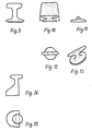
- Fig. 8 shows a slider 63, the holding part (65) and web (67) can be designed according to one of the above-described designs.
- the sliding section (69) is not cylindrical, but cuboid. This results in improved guidance of the slider (63) in the guide rail. If the width of the sliding section (69) is matched to the width of the guide channel (17) in the guide rail (9), then this slide (63) can also be used in the guide rail according to FIG. 1 with improved strength and sliding properties.
- FIGS. 9 and 10 show a sliding piece, the holding part of which receives a ceramic insert.
- the ceramic insert shown in more detail in FIGS. 11-13 has the shape of an anvil.
- FIGS. 14 and 15 show a design of a sliding piece in which the holding part is asymmetrical and offset from the sliding part cut is formed. This increases the strength and enables an improved anchoring of a ceramic insert that may be inserted.
Landscapes
- Engineering & Computer Science (AREA)
- Mechanical Engineering (AREA)
- Window Of Vehicle (AREA)
Applications Claiming Priority (2)
| Application Number | Priority Date | Filing Date | Title |
|---|---|---|---|
| DE3806255 | 1988-02-27 | ||
| DE3806255A DE3806255A1 (de) | 1988-02-27 | 1988-02-27 | Gleitstueck fuer fensterfuehrungen von kraftfahrzeugen |
Publications (3)
| Publication Number | Publication Date |
|---|---|
| EP0330861A2 true EP0330861A2 (fr) | 1989-09-06 |
| EP0330861A3 EP0330861A3 (en) | 1990-03-21 |
| EP0330861B1 EP0330861B1 (fr) | 1991-09-04 |
Family
ID=6348333
Family Applications (1)
| Application Number | Title | Priority Date | Filing Date |
|---|---|---|---|
| EP89102002A Expired - Lifetime EP0330861B1 (fr) | 1988-02-27 | 1989-02-06 | Glissoir pour guides de fenêtres de véhicules automobiles |
Country Status (3)
| Country | Link |
|---|---|
| EP (1) | EP0330861B1 (fr) |
| DE (2) | DE3806255A1 (fr) |
| ES (1) | ES2025341B3 (fr) |
Cited By (1)
| Publication number | Priority date | Publication date | Assignee | Title |
|---|---|---|---|---|
| FR2719811A1 (fr) * | 1994-05-11 | 1995-11-17 | Renault | Montant de vitre de porte latérale de véhicule automobile. |
Families Citing this family (2)
| Publication number | Priority date | Publication date | Assignee | Title |
|---|---|---|---|---|
| DE4210035A1 (de) * | 1992-03-27 | 1993-09-30 | Audi Ag | Scheibenführung |
| DE10339524A1 (de) * | 2003-08-21 | 2005-03-17 | Brose Fahrzeugteile Gmbh & Co. Kommanditgesellschaft, Coburg | Kraftfahrzeugfensterheber |
Family Cites Families (8)
| Publication number | Priority date | Publication date | Assignee | Title |
|---|---|---|---|---|
| DE3149073C2 (de) * | 1981-12-11 | 1986-03-06 | Rockwell Golde Gmbh, 6000 Frankfurt | Vorrichtung zur Führung und Betätigung eines vertikal verschiebbaren Fahrzeugfensters |
| US4457109A (en) * | 1982-02-26 | 1984-07-03 | Schlegel Corporation | Flush glass window assembly for automotive vehicle |
| DE3209206A1 (de) * | 1982-03-13 | 1983-09-29 | Audi Nsu Auto Union Ag, 7107 Neckarsulm | Scheibenfuehrung fuer fahrzeuge |
| DE3312473A1 (de) * | 1983-04-07 | 1984-10-18 | Adam Opel AG, 6090 Rüsselsheim | Anordnung fuer eine in der hoehe verstellbare fensterscheibe |
| DE3320157A1 (de) * | 1983-06-03 | 1984-12-06 | VEGLA Vereinigte Glaswerke GmbH, 5100 Aachen | Glasscheibe, insbesondere autoglasscheibe, mit ueber eine klebeschicht mit ihr verbundenen metallischen halteelementen |
| DE3480913D1 (de) * | 1983-07-18 | 1990-02-08 | Toyota Motor Co Ltd | Tuerkonstruktion im kraftfahrzeug. |
| JPS60166772U (ja) * | 1984-04-12 | 1985-11-06 | トヨタ自動車株式会社 | 自動車のドアガラスガイド構造 |
| JPS6254011U (fr) * | 1985-09-26 | 1987-04-03 |
-
1988
- 1988-02-27 DE DE3806255A patent/DE3806255A1/de not_active Withdrawn
-
1989
- 1989-02-06 DE DE8989102002T patent/DE58900246D1/de not_active Expired - Lifetime
- 1989-02-06 ES ES89102002T patent/ES2025341B3/es not_active Expired - Lifetime
- 1989-02-06 EP EP89102002A patent/EP0330861B1/fr not_active Expired - Lifetime
Cited By (1)
| Publication number | Priority date | Publication date | Assignee | Title |
|---|---|---|---|---|
| FR2719811A1 (fr) * | 1994-05-11 | 1995-11-17 | Renault | Montant de vitre de porte latérale de véhicule automobile. |
Also Published As
| Publication number | Publication date |
|---|---|
| DE3806255A1 (de) | 1989-09-07 |
| ES2025341B3 (es) | 1992-03-16 |
| EP0330861B1 (fr) | 1991-09-04 |
| DE58900246D1 (de) | 1991-10-10 |
| EP0330861A3 (en) | 1990-03-21 |
Similar Documents
| Publication | Publication Date | Title |
|---|---|---|
| EP0282919B1 (fr) | Joint d'étanchéité pour fenêtre | |
| EP0742762B1 (fr) | Procede de production et de montage d'une vitre avec cadre, notamment dans une partie de vehicule | |
| DE68904733T2 (de) | Klebeverbindung einer glasscheibe mit einem metallgegenstand. | |
| DE3901093A1 (de) | Kraftfahrzeugtuer | |
| DE3345431A1 (de) | Sicherheitsgurt-fuehrungsschienenbaueinheit | |
| EP0330861B1 (fr) | Glissoir pour guides de fenêtres de véhicules automobiles | |
| DE69509450T2 (de) | Seitenscheibe mit hohenverstellbarer Position für Kraftfahrzeuge | |
| DE69717010T2 (de) | Senkrecht bewegbare Scheibe eines Kraftfahrzeugfensters | |
| EP0231184A1 (fr) | Vehicule a moteur avec au moins deux vitres laterales. | |
| DE3011386C2 (de) | Fahrzeugkarosserie, insbesondere für Personenkraftwagen | |
| DE10122637B4 (de) | Dichtungsanordnung für eine Kraftfahrzeugtüre und/oder ein Kraftfahrzeugfenster | |
| EP1598227B1 (fr) | Porte pour véhicule | |
| DE3545224C2 (fr) | ||
| EP0593909A1 (fr) | Clip d'ancrage en plastique pour enjoliveurs, protecteurs ou similaires, en particulier pour voitures | |
| DE3523409C1 (de) | Kantenschutz- und Dichtungsprofil | |
| DE4342758C2 (de) | Tür für Fahrzeugkarosserie | |
| EP0304830B1 (fr) | Cadre composé de profilés porteurs en bois, matière plastique ou matière composite | |
| EP0655544A1 (fr) | Croisement de croisillons | |
| DE10216237A1 (de) | Kunststoff-Fensterscheibe für Fahrzeuge | |
| EP0292960A2 (fr) | Poste de véhicule, notamment pour véhicules automobiles | |
| DE69113599T2 (de) | Toleranzausgleichvorrichtung. | |
| DE102012001644A1 (de) | Fensterführungsvorrichtung | |
| DE4339685C2 (de) | Fensterlaufschienenanordnung mit elastischem Dichtprofil | |
| DE2812314C2 (de) | Fensterheber für ein schiebbares Fenster, insbesondere für Kraftfahrzeuge | |
| DE10129582A1 (de) | Türaußenspiegel und insbesondere einen Spiegelfuß bzw. Spiegelkörper |
Legal Events
| Date | Code | Title | Description |
|---|---|---|---|
| PUAI | Public reference made under article 153(3) epc to a published international application that has entered the european phase |
Free format text: ORIGINAL CODE: 0009012 |
|
| 17P | Request for examination filed |
Effective date: 19890206 |
|
| AK | Designated contracting states |
Kind code of ref document: A2 Designated state(s): DE ES FR GB IT |
|
| PUAL | Search report despatched |
Free format text: ORIGINAL CODE: 0009013 |
|
| AK | Designated contracting states |
Kind code of ref document: A3 Designated state(s): DE ES FR GB IT |
|
| 17Q | First examination report despatched |
Effective date: 19910213 |
|
| ITF | It: translation for a ep patent filed | ||
| GRAA | (expected) grant |
Free format text: ORIGINAL CODE: 0009210 |
|
| AK | Designated contracting states |
Kind code of ref document: B1 Designated state(s): DE ES FR GB IT |
|
| REF | Corresponds to: |
Ref document number: 58900246 Country of ref document: DE Date of ref document: 19911010 |
|
| GBT | Gb: translation of ep patent filed (gb section 77(6)(a)/1977) | ||
| ET | Fr: translation filed | ||
| REG | Reference to a national code |
Ref country code: ES Ref legal event code: FG2A Ref document number: 2025341 Country of ref document: ES Kind code of ref document: B3 |
|
| PLBE | No opposition filed within time limit |
Free format text: ORIGINAL CODE: 0009261 |
|
| STAA | Information on the status of an ep patent application or granted ep patent |
Free format text: STATUS: NO OPPOSITION FILED WITHIN TIME LIMIT |
|
| 26N | No opposition filed | ||
| REG | Reference to a national code |
Ref country code: GB Ref legal event code: IF02 |
|
| PGFP | Annual fee paid to national office [announced via postgrant information from national office to epo] |
Ref country code: ES Payment date: 20080225 Year of fee payment: 20 |
|
| PGFP | Annual fee paid to national office [announced via postgrant information from national office to epo] |
Ref country code: GB Payment date: 20080219 Year of fee payment: 20 Ref country code: IT Payment date: 20080221 Year of fee payment: 20 Ref country code: DE Payment date: 20080229 Year of fee payment: 20 |
|
| PGFP | Annual fee paid to national office [announced via postgrant information from national office to epo] |
Ref country code: FR Payment date: 20080215 Year of fee payment: 20 |
|
| REG | Reference to a national code |
Ref country code: GB Ref legal event code: PE20 Expiry date: 20090205 |
|
| REG | Reference to a national code |
Ref country code: ES Ref legal event code: FD2A Effective date: 20090207 |
|
| PG25 | Lapsed in a contracting state [announced via postgrant information from national office to epo] |
Ref country code: GB Free format text: LAPSE BECAUSE OF EXPIRATION OF PROTECTION Effective date: 20090205 |
|
| PG25 | Lapsed in a contracting state [announced via postgrant information from national office to epo] |
Ref country code: ES Free format text: LAPSE BECAUSE OF EXPIRATION OF PROTECTION Effective date: 20090207 |