EP0330885A1 - Fahrzeugscheinwerfer - Google Patents
Fahrzeugscheinwerfer Download PDFInfo
- Publication number
- EP0330885A1 EP0330885A1 EP89102307A EP89102307A EP0330885A1 EP 0330885 A1 EP0330885 A1 EP 0330885A1 EP 89102307 A EP89102307 A EP 89102307A EP 89102307 A EP89102307 A EP 89102307A EP 0330885 A1 EP0330885 A1 EP 0330885A1
- Authority
- EP
- European Patent Office
- Prior art keywords
- bolt
- receiving part
- reflector
- sleeve
- housing
- Prior art date
- Legal status (The legal status is an assumption and is not a legal conclusion. Google has not performed a legal analysis and makes no representation as to the accuracy of the status listed.)
- Granted
Links
Images

Classifications
-
- B—PERFORMING OPERATIONS; TRANSPORTING
- B60—VEHICLES IN GENERAL
- B60Q—ARRANGEMENT OF SIGNALLING OR LIGHTING DEVICES, THE MOUNTING OR SUPPORTING THEREOF OR CIRCUITS THEREFOR, FOR VEHICLES IN GENERAL
- B60Q1/00—Arrangement of optical signalling or lighting devices, the mounting or supporting thereof or circuits therefor
- B60Q1/02—Arrangement of optical signalling or lighting devices, the mounting or supporting thereof or circuits therefor the devices being primarily intended to illuminate the way ahead or to illuminate other areas of way or environments
- B60Q1/04—Arrangement of optical signalling or lighting devices, the mounting or supporting thereof or circuits therefor the devices being primarily intended to illuminate the way ahead or to illuminate other areas of way or environments the devices being headlights
- B60Q1/06—Arrangement of optical signalling or lighting devices, the mounting or supporting thereof or circuits therefor the devices being primarily intended to illuminate the way ahead or to illuminate other areas of way or environments the devices being headlights adjustable, e.g. remotely-controlled from inside vehicle
- B60Q1/068—Arrangement of optical signalling or lighting devices, the mounting or supporting thereof or circuits therefor the devices being primarily intended to illuminate the way ahead or to illuminate other areas of way or environments the devices being headlights adjustable, e.g. remotely-controlled from inside vehicle by mechanical means
- B60Q1/0683—Adjustable by rotation of a screw
-
- B—PERFORMING OPERATIONS; TRANSPORTING
- B60—VEHICLES IN GENERAL
- B60Q—ARRANGEMENT OF SIGNALLING OR LIGHTING DEVICES, THE MOUNTING OR SUPPORTING THEREOF OR CIRCUITS THEREFOR, FOR VEHICLES IN GENERAL
- B60Q2200/00—Special features or arrangements of vehicle headlamps
- B60Q2200/30—Special arrangements for adjusting headlamps, e.g. means for transmitting the movements for adjusting the lamps
- B60Q2200/32—Ball-joints
Definitions
- the invention relates to a vehicle headlight with the features: the reflector inserted in a housing can optionally be pivoted about two perpendicular axes and is mounted in two adjustable pivot points and a third pivot point, at least one pivot point is formed by a spherical head and a receiving part rigidly connected to the reflector, the ball head is arranged on the free end of a bolt, the longitudinal axis of which is approximately parallel to the optical axis of the headlamp, an opening is made in the rear of the housing, into which the bolt engages,
- the bolt has a threaded shaft which is screwed into a nut inserted in the opening in the rear of the housing.
- a rotary knob is fastened to the end section of the bolt protruding from the housing, while the ball head of the bolt arranged in the interior of the housing is inserted in a self-locking manner into an articulated socket of the receiving part rigidly connected to the reflector.
- a loosening of the ball joint connection is necessary if the bolt for the manual adjustment subsequently against a bolt of the Actuator of a headlamp leveling system is to be replaced.
- Such an exchange would be very simple and quick if it could be done from the rear of the headlamp, since the other connections between the reflector and the housing do not have to be disconnected.
- the ball head of its bolt must be pressed into the socket with a relatively large force when mounting an actuator. This can destroy the interior of the actuator.
- a jerky release of the ball joint connection is avoided in a headlight according to DE-OS 35 09 831 if there is a connection between the receiving part and the reflector, which can be released through a further opening in the rear of the housing.
- the reflector In order to be able to exchange the bolt of a fixed point or the bolt of a manual setting device for the bolt of the actuator of a headlamp leveling system, the reflector must be loosened at all three bearing points, since the receiving parts are larger than the openings in the rear of the housing. Such disassembly or assembly of the reflector is very cumbersome and time-consuming.
- the object of the invention is to improve the vehicle headlights described in the generic term such that From its rear, the stationary or manually adjustable bolt carrying the ball head can be jerkily released from the connection between the ball head and the receiving part and can be pulled out of the opening in the rear of the housing.
- the bolt of the actuator of a headlamp leveling system should be able to be inserted smoothly from the rear of the housing with its ball head into the receiving part rigidly connected to the reflector.
- the reflector should be easily adjustable and securely mounted.
- the free end section of the receiving part is designed as a sleeve, the longitudinal axis of which is perpendicular to the longitudinal axis of the bolt, - the inside diameter of the sleeve corresponds to the outside diameter of the ball head, the sleeve, on the side facing the rear of the housing, has a slot running in the direction of the longitudinal extent, through which the bolt projects, - The sleeve is open at least at a free end without a remaining inner edge.
- the ball head can be swung out of the sleeve without jerking. This means that if the bolt is correctly dismantled or assembled, the headlight is not damaged at its bearing points.
- the reflector by hand e.g. B. is pulled through the housing opening serving to change the light bulb through to the rear of the housing.
- the longitudinal axis of the sleeve is perpendicular to the horizontal pivot axis of the reflector he runs.
- the sleeve can follow the pivoting movement of the reflector when the headlight is pivoted about its horizontal axis, so that there is no tension between the housing and the reflector.
- the sleeve has a slot-like opening at its closed end, which opening is open in the direction in which the bolt extends.
- the bolt can also be pressed into the sleeve when it is disassembled in the direction of insertion of the reflector.
- the sleeve is arranged at the free end of a bolt-shaped receiving part, the longitudinal axis of which is approximately perpendicular to the longitudinal axis of the sleeve and which is inserted into an opening or recess of the reflector in a self-locking and / or self-locking manner.
- a blind hole is made in the region of the bolt-shaped receiving part which is inserted into the reflector and circumferential ribs are formed on the outer surface of the bolt-shaped receiving part and bear against the inner surface of the depression or the opening of the reflector under prestress.
- the depression or the opening into which the bolt-shaped receiving part is inserted under prestress tapers conically in the direction of insertion of the receiving part. This ensures a secure fit of the receiving part on the reflector without relatively large pressure forces acting on the inner surface of the recess of the opening of the reflector due to the wedge effect of the bolt-shaped receiving part.
- the reflector (1) is arranged in an interior space formed by the housing (2) and the lens (3) and can be pivoted in it about two axes running perpendicular to one another.
- the axes are formed by two adjustable pivot points (not shown) and a fixed pivot point (4).
- the housing (2) has an opening on its rear side, into which a plastic part (5) is inserted by means of a twist lock.
- a pin (6) is inserted with its free end into the plastic part (5), while the pin has a ball head (7) at its free end projecting into the interior of the housing (2), which ball head (7) is in a sleeve (8) rigidly connected to the reflector (1) receiving part (9) is arranged.
- the longitudinal axis of the bolt (6) runs approximately parallel to the optical axis of the headlight and the longitudinal axis of the sleeve (8) approximately transversely to the longitudinal axis of the bolt (6).
- the sleeve (8) is slotted in the direction of its longitudinal extension on the side facing the rear of the housing (2).
- the width of the slot (10) is larger than the diameter of the bolt (6) so that the bolt (6) when pivoting the Headlamp can not hit the edges of the slot (10).
- the longitudinal axis of the sleeve (8) runs approximately perpendicular to the horizontal pivot axis.
- the sleeve (8) is open at one free end (11) without a remaining edge area, while the other free end (12) of the sleeve has a slot-like opening (13) which extends into the slot (10) in the lateral surface of the sleeve ( 8) passes.
- the slot-like opening (13) has a smaller width than the slot (10) in the lateral surface of the sleeve (8).
- the receiving part (9) carrying the sleeve (8) at a free end is designed in the form of a bolt and has a blind bore (14) in the region which is inserted in the reflector.
- the bolt-shaped receiving part (9) tapers conically towards its free end and has circumferential ribs (15) on its outer surface which taper towards its end face.
- the bolt-shaped receiving part (9) is inserted in a self-clamping manner in a recess (16) in the rear of the reflector (1). So that the bolt-shaped receiving part (9) is held securely in the recess (16), the bolt-shaped receiving part has a molded-on resilient tongue (17) in its central area, the latching lug of which engages in an undercut of the reflector (2) at its free end ( not shown).
- the ball head (7) can be swiveled out of the sleeve (8).
- the actuator of a headlamp leveling system can be installed quickly and easily from the rear of the headlamp, ie without having to remove the reflector from the housing (not shown).
- the ball head of the bolt of the actuator is pivoted into the sleeve and then the actuator is screwed into the opening of the housing.
Landscapes
- Engineering & Computer Science (AREA)
- Mechanical Engineering (AREA)
- Lighting Device Outwards From Vehicle And Optical Signal (AREA)
- Non-Portable Lighting Devices Or Systems Thereof (AREA)
Abstract
Description
- Die Erfindung bezieht sich auf einen Fahrzeugscheinwerfer mit den Merkmalen:
- der in ein Gehäuse eingesetzte Reflektor ist wahlweise um zwei senkrechte aufeinanderstehende Achsen verschwenkbar und in zwei verstellbaren Schwenkpunkten und einem dritten Schwenkpunkt gelagert,
- mindestens ein Schwenkpunkt wird von einem Kugelkopf und einem starr mit dem Reflektor verbundenen Aufnahmeteil gebildet,
- der Kugelkopf ist an dem freien Ende eines Bolzens angeordnet, dessen Längsachse etwa parallel zur optischen Achse des Scheinwerfers verläuft,
- in die Rückseite des Gehäuses ist eine Öffnung eingebracht, in die der Bolzen eingreift, - Bei einem solchen aus der DE-OS 35 09 831 bekannten Scheinwerfer weist der Bolzen einen Gewindeschaft auf, der in eine in der Öffnung der Gehäuserückseite eingesetzte Mutter eingeschraubt ist. An dem aus dem Gehäuse herausragenden Endabschnitt des Bolzens ist ein Drehknopf befestigt, während der im Inneren des Gehäuses angeordnete Kugelkopf des Bolzens selbstrastend in eine Gelenkpfanne des starr mit dem Reflektor verbundenen Aufnahmeteils eingesetzt ist. Ein solches Kugelgelenk ist zwar einfach und schnell zu montieren, jedoch löst sich bei seiner Demontage die Kugelgelenkverbindung bei einer relativ großen Kraft ruckartig. Dadurch kann der Scheinwerfer an seinen Lagerstellen beschädigt werden. Ein Lösen der Kugelgelenkverbindung ist notwendig, wenn der Bolzen für die manuelle Einstellung nachträglich gegen einen Bolzen des Stellgliedes einer Leuchtweiteregelungsanlage ausgetauscht werden soll. Ein solcher Austausch wäre sehr einfach und schnell möglich, wenn er von der Scheinwerferrückseite her erfolgen könnte, da hierbei die anderen Verbindungen zwischen Reflektor und Gehäuse nicht gelöst werden müssen. Außerdem muß bei der Montage eines Stellgliedes der Kugelkopf seines Bolzens mit einer relativ großen Kraft in die Gelenkpfanne eingedrückt werden. Dadurch kann das Innere des Stellgliedes zerstört werden.
- Ein ruckartiges Lösen der Kugelgelenkverbindung wird bei einem Scheinwerfer nach der DE-OS 35 09 831 vermieden, wenn zwischen dem Aufnahmeteil und dem Reflektor eine Verbindung besteht, die durch eine weitere Öffnung in der Gehäuserückseite zu lösen ist. Hierbei muß um einen Austausch des Bolzens eines Festpunktes oder des Bolzens einer manuellen Einstellvorrichtung gegen den Bolzen des Stellgliedes einer Leuchtweiteregelungsanlage vornehmen zu können, der Reflektor an allen drei Lagerstellen gelöst werden, da die Aufnahmeteile größer als die Öffnungen in der Gehäuserückseite sind. Eine solche Demontage bzw. Montage des Reflektors ist sehr umständlich und zeitaufwendig. Würde ein solches Aufnahmeteil bei einem Scheinwerfer (siehe DE-OS 31 49 831) verwendet werden, dessen Reflektor in einem von Lichtscheibe und Gehäuse gebildeten Innenraum angeordnet ist, so müßte der Reflektor nicht nur an allen drei Lagerstellen von dem Gehäuse gelöst werden, sondern es müßte zusätzlich noch die Lichtscheibe von dem Gehäuse abgenommen werden. Dabei könnte die Lichtscheibe und/oder das Gehäuse beschädigt werden. Ferner kann wegen einer unsachgemäßen Montage der Lichtscheibe und wegen der Öffnung in der Gehäuserückseite, durch die hindurch die Verbindung zwischen dem Reflektor und dem Aufnahmeteil gelöst werden kann, Spritzwasser und Schmutz in den Innenraum des Scheinwerfers eindringen.
- Aufgabe der Erfindung ist es, den im Gattungsbegriff beschriebenen Fahrzeugscheinwerfer derart zu verbessern, daß von seiner Rückseite her der den Kugelkopf tragende ortsfeste oder manuell verstellbare Bolzen ruckfrei aus der zwischen Kugelkopf und Aufnahmeteil bestehenden Verbindung lösbar ist und aus der Öffnung der Gehäuserückseite herausziehbar ist. Nach der Demontage des Bolzens soll der Bolzen des Stellgliedes einer Leuchtweiteregelungsanlage von der Gehäuserückseite her mit seinem Kugelkopf ruckfrei in das starr mit dem Reflektor verbundene Aufnahmeteil einsetzbar sein. Dabei soll der Reflektor leichtgängig verstellbar und sicher gelagert sein. Diese Aufgabe wird nach der Erfindung dadurch gelöst, daß
- der freie Endabschnitt des Aufnahmeteils als Hülse ausgebildet ist, deren Längsachse senkrecht zur Längsachse des Bolzens steht,
- der Innendurchmesser der Hülse dem Außendurchmesser des Kugelkopfes entspricht,
- die Hülse, auf der der Gehäuserückseite zugewandten Seite einen in Richtung der Längsausdehnung verlaufenden Schlitz aufweist, durch den der Bolzen hindurchragt,
- die Hülse zumindest an einem freien Ende ohne verbleibenden Innenrand geöffnet ist. - Bei einer solchen Lösung kann der Kugelkopf ruckfrei aus der Hülse herausgeschwenkt werden. Dadurch kommt es bei einer korrekten Demontage bzw. Montage des Bolzens zu keiner Beschädigung des Scheinwerfers an seinen Lagerstellen. Bei der Montage bzw. Demontage des Kugelkopfes ist es hilfreich, wenn der Reflektor von Hand, z. B. durch die dem Glühlampenwechsel dienende Gehäuseöffnung hindurch zur Gehäuserückseite hin gezogen wird.
- Weiterhin ist es vorteilhaft, wenn die Längsachse der Hülse senkrecht zu der horizontalen Schwenkachse des Reflektors erläuft. Dadurch kann die Hülse beim Schwenken des Scheinwerfers um seine horizontale Achse der Schwenkbewegung des Reflektors folgen, so daß keine Verspannungen zwischen Gehäuse und Reflektor entstehen.
- Ein weiterer Vorteil ist es, wenn die Hülse an ihrem geschlossenen Ende eine schlitzartige Öffnung aufweist, die in Richtung in der sich der Bolzen erstreckt, geöffnet ist. Bei einer solchen Lösung kann der Bolzen auch bei seiner Demontage in Einsetzrichtung des Reflektors in die Hülse eingedrückt werden. Dies ist besonders bei einer automatischen Fertigung vorteilhaft. In diesem Zusammenhang ist es weiterhin vorteilhaft, wenn die Hülse an dem freien Ende eines bolzenförmigen Aufnahmeteils angeordnet ist, dessen Längsachse etwa senkrecht zur Längsachse der Hülse verläuft und das selbstrastend und/oder selbstklemmend in eine Öffnung oder Vertiefung des Reflektors eingesetzt ist. Dadurch kann bei einer entgegen der Lichtaustrittsrichtung wirkenden Druckkraft gegen den Reflektor kein das Aufnahmeteil zerstörendes Drehmoment wie bei dem Scheinwerfer nach der DE-OS 35 09 831 auftreten.
- Außerdem ist es vorteilhaft, wenn in dem Bereich des bolzenförmigen Aufnahmeteils der in den Reflektor eingesetzt ist, eine Sackbohrung angebracht ist und an die Mantelfläche des bolzenförmigen Aufnahmeteils umlaufende Rippen angeformt sind, die in der Innenfläche der Vertiefung oder der Öffnung des Reflektors unter Vorspannung anliegen. Hierbei ist es zweckmäßig, wenn die Vertiefung bzw. die Öffnung in die das bolzenförmige Aufnahmeteil unter Vorspannung eingesetzt ist, sich in Einsetzrichtung des Aufnahmeteils konisch verjüngt. Dadurch ist ein sicherer Festsitz des Aufnahmeteils an dem Reflektor gewährleistet, ohne daß durch die Keilwirkung des bolzenförmigen Aufnahmeteils relativ große Druckkräfte auf die Innenfläche der Vertiefung der Öffnung des Reflektors wirken.
- Ferner ist es ein Vorteil, wenn der den Kugelkopf tragende Bolzen mittels eines Drehverschlusses lösbar an dem Gehäuse arretiert ist. Dadurch kann die Verbindung zwischen dem Bolzen und dem Gehäuse leicht und schnell demontiert und montiert werden.
- Die Erfindung ist in der Zeichnung dargestellt und zwar zeigt
- Figur 1 einen mittleren Längsschnitt durch einen ortsfesten Schwenkpunkt eines Scheinwerfers der von dem Kugelkopf eines Bolzens und einem starr mit dem Reflektor verbundenen Aufnahmeteil gebildet wird,
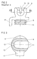
- Figur 2 eine Einzelheit bei X ohne den Bolzen und
- Figur 3 ein Schnitt nach der Linie A-A (um 90° gedreht).
- In der Zeichnung ist der Reflektor (1) in einem von Gehäuse (2) und Lichtscheibe (3) gebildeten Innenraum angeordnet und in diesem um zwei senkrecht zueinander verlaufende Achsen schwenkbar. Die Achsen werden von zwei verstellbaren Schwenkpunkten (nicht dargestellt) und einem ortsfesten Schwenkpunkt (4) gebildet. Das Gehäuse (2) weist auf seiner Rückseite eine Öffnung auf, in welches ein Kunststoffteil (5) mittels eines Drehverschlusses eingesetzt ist. In das Kunststoffteil (5) ist ein Bolzen (6) mit seinem freien Ende klemmend eingesetzt, während der Bolzen an seinem in das Innere des Gehäuses (2) ragenden freien Ende einen Kugelkopf (7) aufweist, welcher in einer Hülse (8) eines starr mit dem Reflektor (1) verbundenen Aufnahmeteils (9) angeordnet ist. Die Längsachse des Bolzens (6) verläuft etwa parallel zur optischen Achse des Scheinwerfers und die Längsachse der Hülse (8) etwa quer zur Längsachse des Bolzens (6). Auf der der Rückseite des Gehäuses (2) zugewandten Seite ist die Hülse (8) in Richtung ihrer Längsausdehnung geschlitzt. Die Breite des Schlitzes (10) ist größer als der Durchmesser des Bolzens (6), damit der Bolzen (6) beim Schwenken des Scheinwerfers nicht an die Ränder des Schlitzes (10) anstoßen kann. Die Längsachse der Hülse (8) verläuft etwa senkrecht zu der horizontal verlaufenden Schwenkachse. Die Hülse (8) ist an einem freien Ende (11) ohne einen verbleibenden Randbereich geöffnet, während das andere freie Ende (12) der Hülse eine schlitzartige Öffnung (13) aufweist, die in den Schlitz (10) in der Mantelfläche der Hülse (8) übergeht. Die schlitzartige Öffnung (13) weist eine kleinere Breite auf als der Schlitz (10) in der Mantelfläche der Hülse (8). Das die Hülse (8) an einem freien Ende tragende Aufnahmeteil (9) ist bolzenförmig ausgeführt und weist in dem Bereich, der in dem Reflektor eingesetzt ist, eine Sackbohrung (14) auf. Das bolzenförmige Aufnahmeteil (9) verjüngt sich zu seinem freien Ende hin konisch und weist an seiner Mantelfläche umlaufende Rippen (15) auf, die sich zu ihrer Stirnfläche hin verjüngen. Das bolzenförmige Aufnahmeteil (9) ist selbstklemmend in eine Vertiefung (16) der Rückseite des Reflektors (1) eingesetzt. Damit das bolzenförmige Aufnahmeteil (9) sicher in der Vertiefung (16) gehalten wird, weist das bolzenförmige Aufnahmeteil in seinem mittleren Bereich eine angeformte federnde Zunge (17) auf, deren Rastnase an ihrem freien Ende in eine Hinterschneidung des Reflektors (2) eingreift (nicht dargestellt). Nach dem Lösen des Drehverschlusses zwischen dem Kunststoffteil (5) und der Öffnung des Gehäuses (2) kann der Kugelkopf (7) aus der Hülse (8) herausgeschwenkt werden. Anschließend kann einfach und schnell von der Scheinwerferrückseite her, d. h. ohne daß der Reflektor aus dem Gehäuse herausgenommen werden muß, das Stellglied einer Leuchtweiteregelungsanlage montiert werden (nicht dargestellt). Hierbei wird zuerst der Kugelkopf des Bolzens des Stellgliedes in die Hülse hereingeschwenkt und danach das Stellglied in die Öffnung des Gehäuses eingeschraubt.
Claims (8)
- der in ein Gehäuse (2) eingesetzte Reflektor (1) ist um zwei senkrecht aufeinanderstehende Achsen verstellbar und in zwei verstellbaren Schwenkpunkten und einem dritten Schwenkpunkt (4) gelagert,
- mindestens ein Schwenkpunkt (4) wird von einem Kugelkopf (7) und einem starr mit dem Reflektor (1) verbundenen Aufnahmeteil (9) gebildet,
- der Kugelkopf (7) ist an dem freien Ende eines Bolzens (6) angeordnet, dessen Längsachse etwa parallel zur optischen Achse des Scheinwerfers verläuft,
- in die Rückseite des Gehäuses (2) ist eine Öffnung eingebracht, in die der Bolzen (6) eingreift,
dadurch gekennzeichnet, daß
- der freie Endabschnitt des Aufnahmeteils (9) als Hülse (8) ausgebildet ist, deren Längsachse senkrecht zur Längsachse des Bolzens (6) steht,
- der Innendurchmesser der Hülse (8), dem Außendurchmesser des Kugelkopfes (7) entspricht,
- die Hülse (8) auf der der Gehäuserückseite zugewandten Seite einen in Richtung ihrer Längsausdehnung verlaufenden Schlitz (10) aufweist, durch den der Bolzen (6) hindurchragt,
- die Hülse (8) zumindest an einem freien Ende ohne verbleibenden Innenrand geöffnet ist.
Applications Claiming Priority (2)
| Application Number | Priority Date | Filing Date | Title |
|---|---|---|---|
| DE8802828U DE8802828U1 (de) | 1988-03-03 | 1988-03-03 | Fahrzeugscheinwerfer |
| DE8802828U | 1988-03-03 |
Publications (2)
| Publication Number | Publication Date |
|---|---|
| EP0330885A1 true EP0330885A1 (de) | 1989-09-06 |
| EP0330885B1 EP0330885B1 (de) | 1991-05-22 |
Family
ID=6821381
Family Applications (1)
| Application Number | Title | Priority Date | Filing Date |
|---|---|---|---|
| EP89102307A Expired - Lifetime EP0330885B1 (de) | 1988-03-03 | 1989-02-10 | Fahrzeugscheinwerfer |
Country Status (6)
| Country | Link |
|---|---|
| EP (1) | EP0330885B1 (de) |
| AU (1) | AU623623B2 (de) |
| BR (1) | BR8900967A (de) |
| DD (1) | DD283672A5 (de) |
| DE (2) | DE8802828U1 (de) |
| ES (1) | ES2022727B3 (de) |
Cited By (3)
| Publication number | Priority date | Publication date | Assignee | Title |
|---|---|---|---|---|
| EP0445911A3 (en) * | 1990-03-06 | 1991-12-11 | Carello Lighting Plc | Lamp assembly |
| FR2702429A1 (fr) * | 1993-03-10 | 1994-09-16 | Valeo Vision | Projecteur pour véhicule automobile comportant des moyens de réglage de l'orientation du réflecteur et procédé de montage de ces moyens. |
| DE102018122676A1 (de) | 2017-09-29 | 2019-04-04 | Varroc Lighting Systems, s.r.o. | Scheinwerfer für Kraftfahrzeuge |
Families Citing this family (1)
| Publication number | Priority date | Publication date | Assignee | Title |
|---|---|---|---|---|
| DE3729984C1 (de) * | 1987-09-08 | 1989-02-09 | Hella Kg Hueck & Co | Kraftfahrzeugscheinwerfer |
Citations (1)
| Publication number | Priority date | Publication date | Assignee | Title |
|---|---|---|---|---|
| DE2537039A1 (de) * | 1975-08-20 | 1977-03-03 | Daimler Benz Ag | Pneumatisch arbeitende regelvorrichtung zur selbsttaetigen ausrichtung von kraftfahrzeugscheinwerfern |
Family Cites Families (8)
| Publication number | Priority date | Publication date | Assignee | Title |
|---|---|---|---|---|
| DE632214C (de) * | 1935-02-19 | 1936-10-10 | Friedrich Stuebbe | Scheinwerfer, insbesondere fuer Kraftfahrzeuge |
| DE7702536U1 (de) * | 1977-01-29 | 1978-07-27 | Robert Bosch Gmbh, 7000 Stuttgart | Kugelzapfenlager, insbesondere fuer kraftfahrzeug-scheinwerfer |
| DE2832395C2 (de) * | 1978-07-24 | 1986-11-06 | Robert Bosch Gmbh, 7000 Stuttgart | Scheinwerfer für Kraftfahrzeuge |
| DE7934640U1 (de) * | 1979-12-08 | 1980-03-13 | Westfaelische Metall Industrie Kg, Hueck & Co, 4780 Lippstadt | Fahrzeugscheinwerfer |
| DE3509831C2 (de) * | 1984-09-04 | 1994-04-14 | Bosch Gmbh Robert | Reflektorbefestigung für Kraftfahrzeugscheinwerfer |
| US4663696A (en) * | 1985-01-31 | 1987-05-05 | Koito Siesakusho Co., Ltd. | Dual purpose lamp assembly for use, for example, as a combined fog and cornering lamp on a motor vehicle |
| JPS639703U (de) * | 1986-07-08 | 1988-01-22 | ||
| US4707770A (en) * | 1986-07-16 | 1987-11-17 | General Motors Corporation | Support shoe for a vehicle headlamp assembly |
-
1988
- 1988-03-03 DE DE8802828U patent/DE8802828U1/de not_active Expired
-
1989
- 1989-01-16 AU AU28511/89A patent/AU623623B2/en not_active Ceased
- 1989-02-10 DE DE8989102307T patent/DE58900120D1/de not_active Expired - Lifetime
- 1989-02-10 EP EP89102307A patent/EP0330885B1/de not_active Expired - Lifetime
- 1989-02-10 ES ES89102307T patent/ES2022727B3/es not_active Expired - Lifetime
- 1989-02-27 DD DD89326063A patent/DD283672A5/de not_active IP Right Cessation
- 1989-03-02 BR BR898900967A patent/BR8900967A/pt not_active IP Right Cessation
Patent Citations (1)
| Publication number | Priority date | Publication date | Assignee | Title |
|---|---|---|---|---|
| DE2537039A1 (de) * | 1975-08-20 | 1977-03-03 | Daimler Benz Ag | Pneumatisch arbeitende regelvorrichtung zur selbsttaetigen ausrichtung von kraftfahrzeugscheinwerfern |
Cited By (5)
| Publication number | Priority date | Publication date | Assignee | Title |
|---|---|---|---|---|
| EP0445911A3 (en) * | 1990-03-06 | 1991-12-11 | Carello Lighting Plc | Lamp assembly |
| US5161876A (en) * | 1990-03-06 | 1992-11-10 | Carello Lighting Public Limited Company | Lamp assembly |
| FR2702429A1 (fr) * | 1993-03-10 | 1994-09-16 | Valeo Vision | Projecteur pour véhicule automobile comportant des moyens de réglage de l'orientation du réflecteur et procédé de montage de ces moyens. |
| DE102018122676A1 (de) | 2017-09-29 | 2019-04-04 | Varroc Lighting Systems, s.r.o. | Scheinwerfer für Kraftfahrzeuge |
| US10414325B2 (en) | 2017-09-29 | 2019-09-17 | Varroc Lighting Systems, s.r.o. | Headlight for motor vehicles |
Also Published As
| Publication number | Publication date |
|---|---|
| DE8802828U1 (de) | 1988-04-28 |
| DD283672A5 (de) | 1990-10-17 |
| ES2022727B3 (es) | 1991-12-01 |
| EP0330885B1 (de) | 1991-05-22 |
| BR8900967A (pt) | 1989-10-24 |
| AU623623B2 (en) | 1992-05-21 |
| DE58900120D1 (de) | 1991-06-27 |
| AU2851189A (en) | 1989-09-07 |
Similar Documents
| Publication | Publication Date | Title |
|---|---|---|
| DE69709446T2 (de) | Vorrichtung zur Kontrolle der Neigung eines Scheinwerfers | |
| DE69804149T2 (de) | Verriegelungshebelmechanismus für Verbinder | |
| DD299079A5 (de) | Bausatz fuer ein tragwerk oder geruest mit staeben und kupplungen zu deren verbinden | |
| DE69015097T2 (de) | Kraftfahrzeugskarosseriekomponente, umfassend eine Beleuchtungsvorrichtung. | |
| DE69513887T2 (de) | Verbindungsanordnung mit Spreizdübbel mit Positionierung für Kleinteile, insbesondere für Auszugführungen | |
| WO2021032346A1 (de) | Halteanordnung und verfahren zur hängenden montage eines objekts, insbesondere einer überwachungskamera | |
| EP0330885B1 (de) | Fahrzeugscheinwerfer | |
| EP0393353A1 (de) | Scheinwerfer für Fahrzeuge | |
| EP0455251A2 (de) | Abnehmbare Anhängerkupplung | |
| EP0330884B1 (de) | Fahrzeugscheinwerfer | |
| EP1085257B1 (de) | Beleuchtungsscheinwerfer mit Verdrehschutz | |
| DE69605063T2 (de) | Scheinwerfer | |
| DE10309087A1 (de) | Befestigungseinrichtung für Kraftfahrzeug-Scheinwerfer | |
| DE19507586A1 (de) | Scheinwerfer für Fahrzeuge | |
| DE4216612A1 (de) | Einachsscharnier | |
| DE10118150B4 (de) | Befestigungsvorrichtung | |
| DE202016104356U1 (de) | Vorrichtung zur Befestigung eines sanitären Bauteils, insbesondere eines Befestigungsrahmens für eine WC- oder Urinal-Betätigungsplatte | |
| EP1724417A2 (de) | Schlosselement | |
| DE3837807A1 (de) | Scheinwerfer | |
| DE202010001441U1 (de) | Justiersystem für Bauelemente | |
| DE29510396U1 (de) | Schraube versehen mit Lösungsschutz | |
| DE2734520C3 (de) | Schalungszuganker aus Kunststoff | |
| DE9400736U1 (de) | Verbindungsstück für Rohre von Möbelgestellen | |
| EP3933337A1 (de) | Montagevorrichtung zur lösbaren befestigung eines schafts an einem systemkasten einer schusswaffe | |
| CH656178A5 (en) | Hinge for the adjustable fastening of a door wing or window wing having an overlap |
Legal Events
| Date | Code | Title | Description |
|---|---|---|---|
| PUAI | Public reference made under article 153(3) epc to a published international application that has entered the european phase |
Free format text: ORIGINAL CODE: 0009012 |
|
| AK | Designated contracting states |
Kind code of ref document: A1 Designated state(s): DE ES FR GB IT SE |
|
| 17P | Request for examination filed |
Effective date: 19900117 |
|
| 17Q | First examination report despatched |
Effective date: 19901107 |
|
| ITF | It: translation for a ep patent filed | ||
| GRAA | (expected) grant |
Free format text: ORIGINAL CODE: 0009210 |
|
| AK | Designated contracting states |
Kind code of ref document: B1 Designated state(s): DE ES FR GB IT SE |
|
| GBT | Gb: translation of ep patent filed (gb section 77(6)(a)/1977) | ||
| REF | Corresponds to: |
Ref document number: 58900120 Country of ref document: DE Date of ref document: 19910627 |
|
| ET | Fr: translation filed | ||
| PLBE | No opposition filed within time limit |
Free format text: ORIGINAL CODE: 0009261 |
|
| STAA | Information on the status of an ep patent application or granted ep patent |
Free format text: STATUS: NO OPPOSITION FILED WITHIN TIME LIMIT |
|
| 26N | No opposition filed | ||
| EAL | Se: european patent in force in sweden |
Ref document number: 89102307.9 |
|
| PGFP | Annual fee paid to national office [announced via postgrant information from national office to epo] |
Ref country code: GB Payment date: 19990122 Year of fee payment: 11 |
|
| PGFP | Annual fee paid to national office [announced via postgrant information from national office to epo] |
Ref country code: SE Payment date: 19990222 Year of fee payment: 11 |
|
| PGFP | Annual fee paid to national office [announced via postgrant information from national office to epo] |
Ref country code: ES Payment date: 20000207 Year of fee payment: 12 |
|
| PG25 | Lapsed in a contracting state [announced via postgrant information from national office to epo] |
Ref country code: GB Free format text: LAPSE BECAUSE OF NON-PAYMENT OF DUE FEES Effective date: 20000210 |
|
| PG25 | Lapsed in a contracting state [announced via postgrant information from national office to epo] |
Ref country code: SE Free format text: LAPSE BECAUSE OF NON-PAYMENT OF DUE FEES Effective date: 20000211 |
|
| PGFP | Annual fee paid to national office [announced via postgrant information from national office to epo] |
Ref country code: FR Payment date: 20000216 Year of fee payment: 12 |
|
| GBPC | Gb: european patent ceased through non-payment of renewal fee |
Effective date: 20000210 |
|
| EUG | Se: european patent has lapsed |
Ref document number: 89102307.9 |
|
| PG25 | Lapsed in a contracting state [announced via postgrant information from national office to epo] |
Ref country code: ES Free format text: LAPSE BECAUSE OF NON-PAYMENT OF DUE FEES Effective date: 20010212 |
|
| PG25 | Lapsed in a contracting state [announced via postgrant information from national office to epo] |
Ref country code: FR Free format text: LAPSE BECAUSE OF NON-PAYMENT OF DUE FEES Effective date: 20011031 |
|
| REG | Reference to a national code |
Ref country code: FR Ref legal event code: ST |
|
| PGFP | Annual fee paid to national office [announced via postgrant information from national office to epo] |
Ref country code: DE Payment date: 20020315 Year of fee payment: 14 |
|
| REG | Reference to a national code |
Ref country code: ES Ref legal event code: FD2A Effective date: 20021016 |
|
| PG25 | Lapsed in a contracting state [announced via postgrant information from national office to epo] |
Ref country code: DE Free format text: LAPSE BECAUSE OF NON-PAYMENT OF DUE FEES Effective date: 20030902 |
|
| PG25 | Lapsed in a contracting state [announced via postgrant information from national office to epo] |
Ref country code: IT Free format text: LAPSE BECAUSE OF NON-PAYMENT OF DUE FEES;WARNING: LAPSES OF ITALIAN PATENTS WITH EFFECTIVE DATE BEFORE 2007 MAY HAVE OCCURRED AT ANY TIME BEFORE 2007. THE CORRECT EFFECTIVE DATE MAY BE DIFFERENT FROM THE ONE RECORDED. Effective date: 20050210 |