EP0330885A1 - Phare de véhicule - Google Patents
Phare de véhicule Download PDFInfo
- Publication number
- EP0330885A1 EP0330885A1 EP89102307A EP89102307A EP0330885A1 EP 0330885 A1 EP0330885 A1 EP 0330885A1 EP 89102307 A EP89102307 A EP 89102307A EP 89102307 A EP89102307 A EP 89102307A EP 0330885 A1 EP0330885 A1 EP 0330885A1
- Authority
- EP
- European Patent Office
- Prior art keywords
- bolt
- receiving part
- reflector
- sleeve
- housing
- Prior art date
- Legal status (The legal status is an assumption and is not a legal conclusion. Google has not performed a legal analysis and makes no representation as to the accuracy of the status listed.)
- Granted
Links
Images

Classifications
-
- B—PERFORMING OPERATIONS; TRANSPORTING
- B60—VEHICLES IN GENERAL
- B60Q—ARRANGEMENT OF SIGNALLING OR LIGHTING DEVICES, THE MOUNTING OR SUPPORTING THEREOF OR CIRCUITS THEREFOR, FOR VEHICLES IN GENERAL
- B60Q1/00—Arrangement of optical signalling or lighting devices, the mounting or supporting thereof or circuits therefor
- B60Q1/02—Arrangement of optical signalling or lighting devices, the mounting or supporting thereof or circuits therefor the devices being primarily intended to illuminate the way ahead or to illuminate other areas of way or environments
- B60Q1/04—Arrangement of optical signalling or lighting devices, the mounting or supporting thereof or circuits therefor the devices being primarily intended to illuminate the way ahead or to illuminate other areas of way or environments the devices being headlights
- B60Q1/06—Arrangement of optical signalling or lighting devices, the mounting or supporting thereof or circuits therefor the devices being primarily intended to illuminate the way ahead or to illuminate other areas of way or environments the devices being headlights adjustable, e.g. remotely-controlled from inside vehicle
- B60Q1/068—Arrangement of optical signalling or lighting devices, the mounting or supporting thereof or circuits therefor the devices being primarily intended to illuminate the way ahead or to illuminate other areas of way or environments the devices being headlights adjustable, e.g. remotely-controlled from inside vehicle by mechanical means
- B60Q1/0683—Adjustable by rotation of a screw
-
- B—PERFORMING OPERATIONS; TRANSPORTING
- B60—VEHICLES IN GENERAL
- B60Q—ARRANGEMENT OF SIGNALLING OR LIGHTING DEVICES, THE MOUNTING OR SUPPORTING THEREOF OR CIRCUITS THEREFOR, FOR VEHICLES IN GENERAL
- B60Q2200/00—Special features or arrangements of vehicle headlamps
- B60Q2200/30—Special arrangements for adjusting headlamps, e.g. means for transmitting the movements for adjusting the lamps
- B60Q2200/32—Ball-joints
Definitions
- the invention relates to a vehicle headlight with the features: the reflector inserted in a housing can optionally be pivoted about two perpendicular axes and is mounted in two adjustable pivot points and a third pivot point, at least one pivot point is formed by a spherical head and a receiving part rigidly connected to the reflector, the ball head is arranged on the free end of a bolt, the longitudinal axis of which is approximately parallel to the optical axis of the headlamp, an opening is made in the rear of the housing, into which the bolt engages,
- the bolt has a threaded shaft which is screwed into a nut inserted in the opening in the rear of the housing.
- a rotary knob is fastened to the end section of the bolt protruding from the housing, while the ball head of the bolt arranged in the interior of the housing is inserted in a self-locking manner into an articulated socket of the receiving part rigidly connected to the reflector.
- a loosening of the ball joint connection is necessary if the bolt for the manual adjustment subsequently against a bolt of the Actuator of a headlamp leveling system is to be replaced.
- Such an exchange would be very simple and quick if it could be done from the rear of the headlamp, since the other connections between the reflector and the housing do not have to be disconnected.
- the ball head of its bolt must be pressed into the socket with a relatively large force when mounting an actuator. This can destroy the interior of the actuator.
- a jerky release of the ball joint connection is avoided in a headlight according to DE-OS 35 09 831 if there is a connection between the receiving part and the reflector, which can be released through a further opening in the rear of the housing.
- the reflector In order to be able to exchange the bolt of a fixed point or the bolt of a manual setting device for the bolt of the actuator of a headlamp leveling system, the reflector must be loosened at all three bearing points, since the receiving parts are larger than the openings in the rear of the housing. Such disassembly or assembly of the reflector is very cumbersome and time-consuming.
- the object of the invention is to improve the vehicle headlights described in the generic term such that From its rear, the stationary or manually adjustable bolt carrying the ball head can be jerkily released from the connection between the ball head and the receiving part and can be pulled out of the opening in the rear of the housing.
- the bolt of the actuator of a headlamp leveling system should be able to be inserted smoothly from the rear of the housing with its ball head into the receiving part rigidly connected to the reflector.
- the reflector should be easily adjustable and securely mounted.
- the free end section of the receiving part is designed as a sleeve, the longitudinal axis of which is perpendicular to the longitudinal axis of the bolt, - the inside diameter of the sleeve corresponds to the outside diameter of the ball head, the sleeve, on the side facing the rear of the housing, has a slot running in the direction of the longitudinal extent, through which the bolt projects, - The sleeve is open at least at a free end without a remaining inner edge.
- the ball head can be swung out of the sleeve without jerking. This means that if the bolt is correctly dismantled or assembled, the headlight is not damaged at its bearing points.
- the reflector by hand e.g. B. is pulled through the housing opening serving to change the light bulb through to the rear of the housing.
- the longitudinal axis of the sleeve is perpendicular to the horizontal pivot axis of the reflector he runs.
- the sleeve can follow the pivoting movement of the reflector when the headlight is pivoted about its horizontal axis, so that there is no tension between the housing and the reflector.
- the sleeve has a slot-like opening at its closed end, which opening is open in the direction in which the bolt extends.
- the bolt can also be pressed into the sleeve when it is disassembled in the direction of insertion of the reflector.
- the sleeve is arranged at the free end of a bolt-shaped receiving part, the longitudinal axis of which is approximately perpendicular to the longitudinal axis of the sleeve and which is inserted into an opening or recess of the reflector in a self-locking and / or self-locking manner.
- a blind hole is made in the region of the bolt-shaped receiving part which is inserted into the reflector and circumferential ribs are formed on the outer surface of the bolt-shaped receiving part and bear against the inner surface of the depression or the opening of the reflector under prestress.
- the depression or the opening into which the bolt-shaped receiving part is inserted under prestress tapers conically in the direction of insertion of the receiving part. This ensures a secure fit of the receiving part on the reflector without relatively large pressure forces acting on the inner surface of the recess of the opening of the reflector due to the wedge effect of the bolt-shaped receiving part.
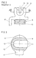
- the reflector (1) is arranged in an interior space formed by the housing (2) and the lens (3) and can be pivoted in it about two axes running perpendicular to one another.
- the axes are formed by two adjustable pivot points (not shown) and a fixed pivot point (4).
- the housing (2) has an opening on its rear side, into which a plastic part (5) is inserted by means of a twist lock.
- a pin (6) is inserted with its free end into the plastic part (5), while the pin has a ball head (7) at its free end projecting into the interior of the housing (2), which ball head (7) is in a sleeve (8) rigidly connected to the reflector (1) receiving part (9) is arranged.
- the longitudinal axis of the bolt (6) runs approximately parallel to the optical axis of the headlight and the longitudinal axis of the sleeve (8) approximately transversely to the longitudinal axis of the bolt (6).
- the sleeve (8) is slotted in the direction of its longitudinal extension on the side facing the rear of the housing (2).
- the width of the slot (10) is larger than the diameter of the bolt (6) so that the bolt (6) when pivoting the Headlamp can not hit the edges of the slot (10).
- the longitudinal axis of the sleeve (8) runs approximately perpendicular to the horizontal pivot axis.
- the sleeve (8) is open at one free end (11) without a remaining edge area, while the other free end (12) of the sleeve has a slot-like opening (13) which extends into the slot (10) in the lateral surface of the sleeve ( 8) passes.
- the slot-like opening (13) has a smaller width than the slot (10) in the lateral surface of the sleeve (8).
- the receiving part (9) carrying the sleeve (8) at a free end is designed in the form of a bolt and has a blind bore (14) in the region which is inserted in the reflector.
- the bolt-shaped receiving part (9) tapers conically towards its free end and has circumferential ribs (15) on its outer surface which taper towards its end face.
- the bolt-shaped receiving part (9) is inserted in a self-clamping manner in a recess (16) in the rear of the reflector (1). So that the bolt-shaped receiving part (9) is held securely in the recess (16), the bolt-shaped receiving part has a molded-on resilient tongue (17) in its central area, the latching lug of which engages in an undercut of the reflector (2) at its free end ( not shown).
- the ball head (7) can be swiveled out of the sleeve (8).
- the actuator of a headlamp leveling system can be installed quickly and easily from the rear of the headlamp, ie without having to remove the reflector from the housing (not shown).
- the ball head of the bolt of the actuator is pivoted into the sleeve and then the actuator is screwed into the opening of the housing.
Landscapes
- Engineering & Computer Science (AREA)
- Mechanical Engineering (AREA)
- Lighting Device Outwards From Vehicle And Optical Signal (AREA)
- Non-Portable Lighting Devices Or Systems Thereof (AREA)
Applications Claiming Priority (2)
| Application Number | Priority Date | Filing Date | Title |
|---|---|---|---|
| DE8802828U DE8802828U1 (de) | 1988-03-03 | 1988-03-03 | Fahrzeugscheinwerfer |
| DE8802828U | 1988-03-03 |
Publications (2)
| Publication Number | Publication Date |
|---|---|
| EP0330885A1 true EP0330885A1 (fr) | 1989-09-06 |
| EP0330885B1 EP0330885B1 (fr) | 1991-05-22 |
Family
ID=6821381
Family Applications (1)
| Application Number | Title | Priority Date | Filing Date |
|---|---|---|---|
| EP89102307A Expired - Lifetime EP0330885B1 (fr) | 1988-03-03 | 1989-02-10 | Phare de véhicule |
Country Status (6)
| Country | Link |
|---|---|
| EP (1) | EP0330885B1 (fr) |
| AU (1) | AU623623B2 (fr) |
| BR (1) | BR8900967A (fr) |
| DD (1) | DD283672A5 (fr) |
| DE (2) | DE8802828U1 (fr) |
| ES (1) | ES2022727B3 (fr) |
Cited By (3)
| Publication number | Priority date | Publication date | Assignee | Title |
|---|---|---|---|---|
| EP0445911A3 (en) * | 1990-03-06 | 1991-12-11 | Carello Lighting Plc | Lamp assembly |
| FR2702429A1 (fr) * | 1993-03-10 | 1994-09-16 | Valeo Vision | Projecteur pour véhicule automobile comportant des moyens de réglage de l'orientation du réflecteur et procédé de montage de ces moyens. |
| DE102018122676A1 (de) | 2017-09-29 | 2019-04-04 | Varroc Lighting Systems, s.r.o. | Scheinwerfer für Kraftfahrzeuge |
Families Citing this family (1)
| Publication number | Priority date | Publication date | Assignee | Title |
|---|---|---|---|---|
| DE3729984C1 (de) * | 1987-09-08 | 1989-02-09 | Hella Kg Hueck & Co | Kraftfahrzeugscheinwerfer |
Citations (1)
| Publication number | Priority date | Publication date | Assignee | Title |
|---|---|---|---|---|
| DE2537039A1 (de) * | 1975-08-20 | 1977-03-03 | Daimler Benz Ag | Pneumatisch arbeitende regelvorrichtung zur selbsttaetigen ausrichtung von kraftfahrzeugscheinwerfern |
Family Cites Families (8)
| Publication number | Priority date | Publication date | Assignee | Title |
|---|---|---|---|---|
| DE632214C (de) * | 1935-02-19 | 1936-10-10 | Friedrich Stuebbe | Scheinwerfer, insbesondere fuer Kraftfahrzeuge |
| DE7702536U1 (de) * | 1977-01-29 | 1978-07-27 | Robert Bosch Gmbh, 7000 Stuttgart | Kugelzapfenlager, insbesondere fuer kraftfahrzeug-scheinwerfer |
| DE2832395C2 (de) * | 1978-07-24 | 1986-11-06 | Robert Bosch Gmbh, 7000 Stuttgart | Scheinwerfer für Kraftfahrzeuge |
| DE7934640U1 (de) * | 1979-12-08 | 1980-03-13 | Westfaelische Metall Industrie Kg, Hueck & Co, 4780 Lippstadt | Fahrzeugscheinwerfer |
| DE3509831C2 (de) * | 1984-09-04 | 1994-04-14 | Bosch Gmbh Robert | Reflektorbefestigung für Kraftfahrzeugscheinwerfer |
| US4663696A (en) * | 1985-01-31 | 1987-05-05 | Koito Siesakusho Co., Ltd. | Dual purpose lamp assembly for use, for example, as a combined fog and cornering lamp on a motor vehicle |
| JPS639703U (fr) * | 1986-07-08 | 1988-01-22 | ||
| US4707770A (en) * | 1986-07-16 | 1987-11-17 | General Motors Corporation | Support shoe for a vehicle headlamp assembly |
-
1988
- 1988-03-03 DE DE8802828U patent/DE8802828U1/de not_active Expired
-
1989
- 1989-01-16 AU AU28511/89A patent/AU623623B2/en not_active Ceased
- 1989-02-10 EP EP89102307A patent/EP0330885B1/fr not_active Expired - Lifetime
- 1989-02-10 DE DE8989102307T patent/DE58900120D1/de not_active Expired - Lifetime
- 1989-02-10 ES ES89102307T patent/ES2022727B3/es not_active Expired - Lifetime
- 1989-02-27 DD DD89326063A patent/DD283672A5/de not_active IP Right Cessation
- 1989-03-02 BR BR898900967A patent/BR8900967A/pt not_active IP Right Cessation
Patent Citations (1)
| Publication number | Priority date | Publication date | Assignee | Title |
|---|---|---|---|---|
| DE2537039A1 (de) * | 1975-08-20 | 1977-03-03 | Daimler Benz Ag | Pneumatisch arbeitende regelvorrichtung zur selbsttaetigen ausrichtung von kraftfahrzeugscheinwerfern |
Cited By (5)
| Publication number | Priority date | Publication date | Assignee | Title |
|---|---|---|---|---|
| EP0445911A3 (en) * | 1990-03-06 | 1991-12-11 | Carello Lighting Plc | Lamp assembly |
| US5161876A (en) * | 1990-03-06 | 1992-11-10 | Carello Lighting Public Limited Company | Lamp assembly |
| FR2702429A1 (fr) * | 1993-03-10 | 1994-09-16 | Valeo Vision | Projecteur pour véhicule automobile comportant des moyens de réglage de l'orientation du réflecteur et procédé de montage de ces moyens. |
| DE102018122676A1 (de) | 2017-09-29 | 2019-04-04 | Varroc Lighting Systems, s.r.o. | Scheinwerfer für Kraftfahrzeuge |
| US10414325B2 (en) | 2017-09-29 | 2019-09-17 | Varroc Lighting Systems, s.r.o. | Headlight for motor vehicles |
Also Published As
| Publication number | Publication date |
|---|---|
| BR8900967A (pt) | 1989-10-24 |
| DD283672A5 (de) | 1990-10-17 |
| DE8802828U1 (de) | 1988-04-28 |
| EP0330885B1 (fr) | 1991-05-22 |
| ES2022727B3 (es) | 1991-12-01 |
| AU623623B2 (en) | 1992-05-21 |
| DE58900120D1 (de) | 1991-06-27 |
| AU2851189A (en) | 1989-09-07 |
Similar Documents
| Publication | Publication Date | Title |
|---|---|---|
| EP0870982B1 (fr) | Lampe à encastrer | |
| DE69709446T2 (de) | Vorrichtung zur Kontrolle der Neigung eines Scheinwerfers | |
| DE69804149T2 (de) | Verriegelungshebelmechanismus für Verbinder | |
| DD299079A5 (de) | Bausatz fuer ein tragwerk oder geruest mit staeben und kupplungen zu deren verbinden | |
| DE69015097T2 (de) | Kraftfahrzeugskarosseriekomponente, umfassend eine Beleuchtungsvorrichtung. | |
| WO2021032346A1 (fr) | Ensemble de maintien et procédé de montage suspendu d'un objet, en particulier d'une caméra de sécurité | |
| EP0330885B1 (fr) | Phare de véhicule | |
| DE9005050U1 (de) | Kupplungsstange für eine abnehmbare Anhängerkupplung | |
| DE3509831A1 (de) | Scheinwerfer fuer kraftfahrzeuge | |
| EP0393353A1 (fr) | Phare pour véhicule | |
| DE3222954C2 (de) | Lichtschrankeneinheit | |
| EP0330884B1 (fr) | Phare de véhicule | |
| EP1085257B1 (fr) | Projecteur d'éclairage avec verrouillage de l'articulation | |
| DE69605063T2 (de) | Scheinwerfer | |
| DE10309087A1 (de) | Befestigungseinrichtung für Kraftfahrzeug-Scheinwerfer | |
| DE19507586A1 (de) | Scheinwerfer für Fahrzeuge | |
| DE4216612A1 (de) | Einachsscharnier | |
| DE10118150B4 (de) | Befestigungsvorrichtung | |
| DE202016104356U1 (de) | Vorrichtung zur Befestigung eines sanitären Bauteils, insbesondere eines Befestigungsrahmens für eine WC- oder Urinal-Betätigungsplatte | |
| EP1724417A2 (fr) | Élément de serrure | |
| DE3837807A1 (de) | Scheinwerfer | |
| DE202010001441U1 (de) | Justiersystem für Bauelemente | |
| DE29510396U1 (de) | Schraube versehen mit Lösungsschutz | |
| DE2734520C3 (de) | Schalungszuganker aus Kunststoff | |
| DE9400736U1 (de) | Verbindungsstück für Rohre von Möbelgestellen |
Legal Events
| Date | Code | Title | Description |
|---|---|---|---|
| PUAI | Public reference made under article 153(3) epc to a published international application that has entered the european phase |
Free format text: ORIGINAL CODE: 0009012 |
|
| AK | Designated contracting states |
Kind code of ref document: A1 Designated state(s): DE ES FR GB IT SE |
|
| 17P | Request for examination filed |
Effective date: 19900117 |
|
| 17Q | First examination report despatched |
Effective date: 19901107 |
|
| ITF | It: translation for a ep patent filed | ||
| GRAA | (expected) grant |
Free format text: ORIGINAL CODE: 0009210 |
|
| AK | Designated contracting states |
Kind code of ref document: B1 Designated state(s): DE ES FR GB IT SE |
|
| GBT | Gb: translation of ep patent filed (gb section 77(6)(a)/1977) | ||
| REF | Corresponds to: |
Ref document number: 58900120 Country of ref document: DE Date of ref document: 19910627 |
|
| ET | Fr: translation filed | ||
| PLBE | No opposition filed within time limit |
Free format text: ORIGINAL CODE: 0009261 |
|
| STAA | Information on the status of an ep patent application or granted ep patent |
Free format text: STATUS: NO OPPOSITION FILED WITHIN TIME LIMIT |
|
| 26N | No opposition filed | ||
| EAL | Se: european patent in force in sweden |
Ref document number: 89102307.9 |
|
| PGFP | Annual fee paid to national office [announced via postgrant information from national office to epo] |
Ref country code: GB Payment date: 19990122 Year of fee payment: 11 |
|
| PGFP | Annual fee paid to national office [announced via postgrant information from national office to epo] |
Ref country code: SE Payment date: 19990222 Year of fee payment: 11 |
|
| PGFP | Annual fee paid to national office [announced via postgrant information from national office to epo] |
Ref country code: ES Payment date: 20000207 Year of fee payment: 12 |
|
| PG25 | Lapsed in a contracting state [announced via postgrant information from national office to epo] |
Ref country code: GB Free format text: LAPSE BECAUSE OF NON-PAYMENT OF DUE FEES Effective date: 20000210 |
|
| PG25 | Lapsed in a contracting state [announced via postgrant information from national office to epo] |
Ref country code: SE Free format text: LAPSE BECAUSE OF NON-PAYMENT OF DUE FEES Effective date: 20000211 |
|
| PGFP | Annual fee paid to national office [announced via postgrant information from national office to epo] |
Ref country code: FR Payment date: 20000216 Year of fee payment: 12 |
|
| GBPC | Gb: european patent ceased through non-payment of renewal fee |
Effective date: 20000210 |
|
| EUG | Se: european patent has lapsed |
Ref document number: 89102307.9 |
|
| PG25 | Lapsed in a contracting state [announced via postgrant information from national office to epo] |
Ref country code: ES Free format text: LAPSE BECAUSE OF NON-PAYMENT OF DUE FEES Effective date: 20010212 |
|
| PG25 | Lapsed in a contracting state [announced via postgrant information from national office to epo] |
Ref country code: FR Free format text: LAPSE BECAUSE OF NON-PAYMENT OF DUE FEES Effective date: 20011031 |
|
| REG | Reference to a national code |
Ref country code: FR Ref legal event code: ST |
|
| PGFP | Annual fee paid to national office [announced via postgrant information from national office to epo] |
Ref country code: DE Payment date: 20020315 Year of fee payment: 14 |
|
| REG | Reference to a national code |
Ref country code: ES Ref legal event code: FD2A Effective date: 20021016 |
|
| PG25 | Lapsed in a contracting state [announced via postgrant information from national office to epo] |
Ref country code: DE Free format text: LAPSE BECAUSE OF NON-PAYMENT OF DUE FEES Effective date: 20030902 |
|
| PG25 | Lapsed in a contracting state [announced via postgrant information from national office to epo] |
Ref country code: IT Free format text: LAPSE BECAUSE OF NON-PAYMENT OF DUE FEES;WARNING: LAPSES OF ITALIAN PATENTS WITH EFFECTIVE DATE BEFORE 2007 MAY HAVE OCCURRED AT ANY TIME BEFORE 2007. THE CORRECT EFFECTIVE DATE MAY BE DIFFERENT FROM THE ONE RECORDED. Effective date: 20050210 |