EP0330933B1 - Dispositif pour mesurer l'énergie d'une impulsion micro-onde - Google Patents
Dispositif pour mesurer l'énergie d'une impulsion micro-onde Download PDFInfo
- Publication number
- EP0330933B1 EP0330933B1 EP89102748A EP89102748A EP0330933B1 EP 0330933 B1 EP0330933 B1 EP 0330933B1 EP 89102748 A EP89102748 A EP 89102748A EP 89102748 A EP89102748 A EP 89102748A EP 0330933 B1 EP0330933 B1 EP 0330933B1
- Authority
- EP
- European Patent Office
- Prior art keywords
- vessel
- wall
- absorber liquid
- arrangement according
- medium
- Prior art date
- Legal status (The legal status is an assumption and is not a legal conclusion. Google has not performed a legal analysis and makes no representation as to the accuracy of the status listed.)
- Expired - Lifetime
Links
Images
Classifications
-
- G—PHYSICS
- G01—MEASURING; TESTING
- G01R—MEASURING ELECTRIC VARIABLES; MEASURING MAGNETIC VARIABLES
- G01R21/00—Arrangements for measuring electric power or power factor
- G01R21/02—Arrangements for measuring electric power or power factor by thermal methods, e.g. calorimetric
- G01R21/04—Arrangements for measuring electric power or power factor by thermal methods, e.g. calorimetric in circuits having distributed constants
-
- G—PHYSICS
- G01—MEASURING; TESTING
- G01K—MEASURING TEMPERATURE; MEASURING QUANTITY OF HEAT; THERMALLY-SENSITIVE ELEMENTS NOT OTHERWISE PROVIDED FOR
- G01K17/00—Measuring quantity of heat
- G01K17/003—Measuring quantity of heat for measuring the power of light beams, e.g. laser beams
-
- H—ELECTRICITY
- H01—ELECTRIC ELEMENTS
- H01P—WAVEGUIDES; RESONATORS, LINES, OR OTHER DEVICES OF THE WAVEGUIDE TYPE
- H01P1/00—Auxiliary devices
- H01P1/24—Terminating devices
- H01P1/26—Dissipative terminations
- H01P1/262—Dissipative terminations the dissipative medium being a liquid or being cooled by a liquid
Definitions
- the invention relates to an arrangement for measuring the energy of a microwave pulse according to the preamble of claim 1.
- the above-mentioned arrangement comprises a housing which is closed with a window which is permeable to microwaves and contains a gas which absorbs microwaves and to which a microwave conductor can be coupled.
- a second gas is present in a closed volume in the housing and expands when a microwave pulse is absorbed in the first gas. The volume expansion of this second gas serves as a measure of the energy of the microwave pulse.
- a so-called high-performance calorimeter for high frequency microwaves is e.g. known from US 4,593,259.
- the object of the invention is therefore to provide an arrangement for measuring the energy of a microwave pulse, which is particularly suitable for measuring small energies.
- a non-gassing oil is used as the absorber liquid.
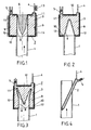
- Fig. 1 shows a section through a preferred arrangement.
- the arrangement according to the invention is arranged coaxially to one end of a waveguide 1. It comprises a vessel 2, which is filled with an absorber liquid 3, a capillary 4 and an equalizing volume 5, both of which are connected to the vessel 2. According to a preferred embodiment, it also has a reflector cone 6.
- the vessel 2 has the shape of a cylinder jacket. I.e. a volume of the vessel 2 is delimited by a cylindrical inner wall 8, a cylindrical outer wall 9 arranged coaxially therewith, and a ring-shaped bottom 10 and a corresponding ceiling 11, which close off the volume in the axial direction.
- the diameter of the inner wall corresponds essentially to the diameter of the waveguide 1.
- the vessel 2 is e.g. made of quartz or glass and has a wall thickness which is preferably less than 1/4 of a wavelength of an incident microwave pulse. It can thereby be achieved that the vessel 2 is transparent to the microwave pulse.
- the reflector cone 6 has the task of scattering the microwave pulse in such a way that its energy is distributed as evenly as possible over the volume of the vessel 2 and thus over the absorber liquid 3. In general, it will be essential to design its shape specifically for the microwave pulse, ie a guided mode of the waveguide 1.
- the reflector cone 6 is designed in two stages according to a preferred embodiment. At its pointed end it has a larger angle of inclination than at its blunt end.
- the outer wall 9, the bottom 10 and the ceiling 11 of the vessel 2 are covered with a reflection layer 12, which prevents a part of the microwave pulse that has not yet been absorbed by the reflector cone 6 from leaving the vessel to the outside.
- the inner wall 8 serves as an RF window. Of course, it should let the scattered microwave pulse pass through as weakly as possible. However, it will not be possible to avoid that part of the microwave pulse is reflected by the inner wall 8 and is again scattered by the reflector cone 6. With a suitably chosen shape of this reflector cone 6, such back and forth reflections can and should be reduced to a minimum.
- the capillary 4 is attached to the ceiling 11 of the vessel 2.
- a rising height of the absorber liquid 3 in the capillary 4 can e.g. can be read on a scale 13.
- the compensation volume 5 is there to level the rise. In Fig. 1 this possibility to change the compensation volume is indicated with a piston.
- the vessel 2 is advantageously kept at a constant working temperature.
- it can e.g. be wrapped by a cooling coil 14, which prevents the arrangement from heating up beyond the ambient temperature. Annoying radiation or Irradiation effects can be avoided.
- a microwave pulse (see arrow), which propagates in the waveguide 1, hits the reflector cone 6 and is scattered in the radial direction.
- a large part of the microwave pulse enters through the inner wall 8, ie the HF window Vessel 2, where it is absorbed by the absorber liquid 3.
- a small part of the microwave pulse will be reflected by the inner wall 8 and then by the reflector cone 6 and thus will not penetrate into the vessel 2 until the second or third attempt.
- the absorber liquid 3 heats up at least in some areas and expands accordingly. Such a thermal volume expansion is measured with the capillary 4.
- the absorber liquid 3 should absorb well in a given wavelength range, on the other hand, however, it must not gas. If gas bubbles form due to local overheating, the thermal volume expansion of the absorber liquid 3 as a whole is highly non-linear. The rise in the capillary 4 no longer clearly indicates an increase in the heat content, i.e. deduce the absorbed energy. In practice, a gassing absorber liquid 3 causes the climbing height to overshoot.
- Hydraulic oils or vacuum oils are used as absorber liquid 3. These are known to have little tendency to gas.
- Another measure is to use an absorber liquid 3 in which the microwave pulse has a high depth of penetration. Less energy is then absorbed in a given volume element, which reduces the risk of local overheating.
- the vessel 2 is advantageously dimensioned so thick (i.e. the radial distance between the outer wall 9 and the inner wall 8) that the scattered microwave pulse is at the latest after passing through the vessel twice, i.e. if after reflection on the mirrored outer wall 9 it has reached the inner wall 8 again, it has run dead.
- a great advantage of the invention is that the measurement does not require a thermal equilibrium. As long as the thermal volume expansion increases linearly with the increase in heat content resp. of the absorbed energy, it does not matter for the height of rise whether a small part of the absorber liquid 3 heats up relatively strongly locally, or whether a correspondingly large part heats up only slightly.
- the volume of the absorber liquid is also important in connection with the stabilization of the working temperature.
- the cooling coil 14, for example, should keep the working temperature constant, ie dissipate the absorbed energy but must not do so quickly that the measurement is affected. If the energy is essentially converted into heat inside the vessel 2 and not in the vicinity of the outer wall 9, it usually takes several seconds until the heat supplied is dissipated via the outer wall 9 due to the heat conduction. In practice, this is enough to determine the final value of the climbing height.
- Another disruptive effect that can be prevented is the thermal expansion of the vessel 2. This depends on how much the vessel 2 heats up because of the continuous microwave pulse and how large its expansion coefficient is. In view of a low expansion coefficient, it is therefore advantageous to use a quartz vessel. A cheaper option is to choose a glass with a high degree of transparency for the microwave pulses to be measured. In any case, it is good to keep the vessel 2 as thin-walled as possible.
- the arrangement can e.g. can be converted very quickly to microwave pulses of higher energy by inserting a larger capillary 4. With the help of the compensating volume 5, the height of the climb can be leveled again.
- the absorber liquid 3 is viscous, it can happen that the capillary 4, which would have to be used due to the expected small thermal volume expansion, is too thin for the absorber liquid 3. In such a case, a thin liquid medium is poured onto the absorber liquid 3. whose specific weight is less than that of the absorber liquid 3.
- the capillary can be optically imaged on a CCD Arrey, which is read out electronically, or the rise height can be measured acoustically by generating a standing wave in the air-filled part of the capillary 4.
- a disadvantage of the arrangement shown in FIG. 1 is that energy which is delivered to the reflector cone 6 is not included in the measurement. This will mainly affect higher energies.
- Fig. 2 shows an arrangement in which the vessel 2 has a conical indentation as an RF window.
- a volume of the vessel 2 is limited by a cylindrical outer wall 9, a conical inner wall 8, in contrast to FIG. 1, a floor 10 and a ceiling 11.
- the microwave pulse radiated from a waveguide 1 slowly runs dead, its energy is also distributed here over the entire absorber liquid 3.
- FIG. 3 shows a further preferred embodiment of the vessel 2.
- the outer wall 9, bottom 10 and ceiling 11 correspond to those of FIG. 2.
- An inner wall 8 is shaped in such a way that it looks M-shaped in axial section.
- a microwave pulse (see arrow), the energy density of which is half
- the maximum radius of the waveguide 1 is absorbed, for example, in such a way that the energy runs into the shoulders of the M-shaped axial section.
- FIGS. 2 and 3 capillary 4, reflective layer 12, etc.
- FIG. 1 The remaining parts shown in FIG. 1, which are not shown in FIGS. 2 and 3, also find their counterparts here.
- Fig. 4 shows an embodiment which is suitable in connection with a rectangular waveguide.
- the vessel 2 is a tube which is inserted into the waveguide 1 at an oblique angle.
- the capillary 4 and the equalizing volume 5 are attached to a part of the tube which protrudes from the waveguide 1.
- the energy of a microwave pulse is measured via the thermal volume expansion of an absorber liquid.
- the shape of the vessel 2 and in particular the shape of the inner wall 8 serving as HF window is of great importance. For optimal transmission, it must be based on the microwave pulse. the guided mode of the waveguide 1 must be matched. In this sense, the exemplary embodiments described are to be regarded as pioneering, but not as comprehensive. In principle, the arrangement according to the invention works with any vessel shape.
Landscapes
- Physics & Mathematics (AREA)
- Engineering & Computer Science (AREA)
- General Physics & Mathematics (AREA)
- Optics & Photonics (AREA)
- Chemical & Material Sciences (AREA)
- Combustion & Propulsion (AREA)
- Power Engineering (AREA)
- Investigating Or Analyzing Materials Using Thermal Means (AREA)
- Measurement Of Levels Of Liquids Or Fluent Solid Materials (AREA)
- Investigating Or Analysing Materials By Optical Means (AREA)
Claims (8)
- Dispositif de mesure de l'énergie d'une impulsion de micro-ondes, comprenant :a) un boîtier fermé par une fenêtre perméable aux micro-ondes, qui contient un premier agent absorbant les micro-ondes et peut être couplé à un guide de micro-ondes (1);b) dans le boîtier, un volume fermé avec un second agent, qui est en contact thermique avec le premier agent et dont le volume se dilate lorsqu'il y a absorption d'une impulsion de micro-ondes dans le premier agent, etc) un capillaire (4) pour indiquer la dilatation du volume, ce capillaire (4) étant en liaison avec le volume fermé;caractérisé en ce que :d) le premier et le second agent forment un agent commun sous la forme d'un liquide absorbant (3);e) on utilise comme liquide absorbant (3) une huile ne dégageant pas de gaz, de préférence, une huile hydraulique ou une huile vacuum;f) le boîtier est un récipient (2) destiné à recevoir le liquide absorbant (3), ayant la forme d'une enveloppe cylindrique, comportant une paroi intérieure (8) et une paroi extérieure (9) et étant agencé avec son axe de cylindre parallèle à la direction de propagation des micro-ondes à mesurer;g) la paroi intérieure (8) est conformée en fenêtre HF (7) et la paroi extérieure (9) réfléchit les micro-ondes, eth) l'épaisseur du récipient (2) entre la paroi intérieure (8) et la paroi extérieure (9) est choisie telle qu'une impulsion de micro-ondes traversant le récipient (2) soit complètement absorbée au plus tard après le second passage.
- Dispositif selon la revendication 1, caractérisé en ce qu'un cône réflecteur (6) est disposé à l'intérieur du récipient (2).
- Dispositif selon la revendication 1, caractérisé en ce que la paroi intérieure (8) a une forme conique.
- Dispositif selon la revendication 1, caractérisé en ce que la paroi intérieure (8) est conformée de manière à avoir en coupe axiale une forme en M.
- Dispositif selon l'une quelconque des revendications 1 à 4, caractérisé en ce que le récipient (2) est en liaison avec un volume de compensation (5) de sorte que, via le volume de compensation (5), on peut niveler la hauteur d'aspiration dans le capillaire (4).
- Dispositif selon l'une quelconque des revendications 1 à 5, caractérisé en ce que :a) le récipient (2) a une paroi mince;b) au moins la paroi extérieure (9) est dotée d'une couche réfléchissante (12);c) le liquide absorbant (3) a un volume qui est si grand que l'augmentation de la chaleur y contenue lors de l'absorption d'une impulsion de micro-ondes ne puisse entraîner qu'une augmentation peu sensible de la température de travail, etd) le récipient (2) est fait d'une matière présentant un coefficient de dilatation thermique faible.
- Dispositif selon l'une quelconque des revendications 1 à 6, caractérisé en ce que la hauteur d'aspiration dans le capillaire (4) est indiquée par un agent fluide, qui est versé sur le liquide absorbant (3) et ne se mélange pas à celui-ci.
- Dispositif selon l'une quelconque des revendications 1 à 7, caractérisé en ce que le récipient (2) est doté de moyens pour maintenir constante la température de travail, de préférence sous la forme d'un serpentin de refroidissement (14) enroulé autour du boîtier (2).
Applications Claiming Priority (2)
| Application Number | Priority Date | Filing Date | Title |
|---|---|---|---|
| CH75688 | 1988-03-02 | ||
| CH756/88 | 1988-03-02 |
Publications (2)
| Publication Number | Publication Date |
|---|---|
| EP0330933A1 EP0330933A1 (fr) | 1989-09-06 |
| EP0330933B1 true EP0330933B1 (fr) | 1993-08-18 |
Family
ID=4194454
Family Applications (1)
| Application Number | Title | Priority Date | Filing Date |
|---|---|---|---|
| EP89102748A Expired - Lifetime EP0330933B1 (fr) | 1988-03-02 | 1989-02-17 | Dispositif pour mesurer l'énergie d'une impulsion micro-onde |
Country Status (4)
| Country | Link |
|---|---|
| US (1) | US4968150A (fr) |
| EP (1) | EP0330933B1 (fr) |
| JP (1) | JPH01316669A (fr) |
| DE (1) | DE58905296D1 (fr) |
Families Citing this family (12)
| Publication number | Priority date | Publication date | Assignee | Title |
|---|---|---|---|---|
| US5099096A (en) * | 1990-04-05 | 1992-03-24 | Martin Marietta Energy Systems, Inc. | Microwave furnace having microwave compatible dilatometer |
| US5302024A (en) * | 1990-10-09 | 1994-04-12 | Lockheed Sanders, Inc. | Monolithic microwave power sensor using a heat sensing diode junction |
| USH1102H (en) | 1991-09-16 | 1992-09-01 | The United States Of America As Represented By The Secretary Of The Navy | Fluidic laser calorimeter |
| DE19528343C2 (de) * | 1995-08-02 | 1997-05-22 | Markus Muehleisen | Vorrichtung zur reflexionsarmen Absorption von Mikrowellen |
| US5749654A (en) * | 1996-01-16 | 1998-05-12 | Gibson, Jr.; Oliver E. | Calorimetric wattmeter for testing microwave ovens |
| US6017147A (en) * | 1996-01-16 | 2000-01-25 | Gibson, Jr.; Oliver E. | Calorimetric wattmeter for testing microwave ovens |
| GB2325053A (en) * | 1997-05-09 | 1998-11-11 | Matra Bae Dynamics | Measurement of microwave radiation |
| USD601911S1 (en) | 2008-09-15 | 2009-10-13 | Moerman Paul G | Calometric wattmeter |
| DE102009054747A1 (de) * | 2009-12-16 | 2011-06-22 | Endress + Hauser Wetzer GmbH + Co. KG, 87484 | Messeinsatz zur Temperaturmessung |
| DE102010061731A1 (de) * | 2010-11-22 | 2012-05-24 | Endress + Hauser Flowtec Ag | Gehäuse eines Temperatursensors, insbesondere eines thermischen Durchflussmessgeräts |
| US9231287B2 (en) * | 2013-09-09 | 2016-01-05 | Raytheon Company | Isothermal terminator and method for determining shape of isothermal terminator |
| RU2659963C1 (ru) * | 2017-09-04 | 2018-07-04 | Анастасия Витальевна Горелова | Жидкостная СВЧ согласованная нагрузка |
Family Cites Families (15)
| Publication number | Priority date | Publication date | Assignee | Title |
|---|---|---|---|---|
| US2451724A (en) * | 1943-08-31 | 1948-10-19 | Rca Corp | Super high frequency wattmeter |
| US2853679A (en) * | 1953-02-09 | 1958-09-23 | Varian Associates | Microwave wattmeter |
| US2850702A (en) * | 1954-09-15 | 1958-09-02 | Richard A White | Measuring apparatus |
| US2846647A (en) * | 1956-06-29 | 1958-08-05 | Alan C Macpherson | Microwave calorimetric wattmeter |
| GB839992A (en) * | 1957-03-15 | 1960-06-29 | Gen Electric Co Ltd | Improvements in or relating to arrangements for measuring the power of electromagnetic oscillations transmitted along a waveguide |
| US3040252A (en) * | 1957-11-14 | 1962-06-19 | Warren D Novak | Radio energy measuring device |
| US3143703A (en) * | 1961-03-27 | 1964-08-04 | Varian Associates | Microwave calorimeter wattmeter with a reflectionless r. f. termination |
| GB1009163A (en) * | 1963-08-29 | 1965-11-10 | Wayne Kerr Lab Ltd | Improvements in or relating to apparatus for measuring or responsive to radio frequency power |
| US3487685A (en) * | 1966-11-01 | 1970-01-06 | Hughes Aircraft Co | Absorption radiometer |
| US3670570A (en) * | 1971-04-30 | 1972-06-20 | Trw Inc | Light intensity calorimeter |
| SU362248A1 (ru) * | 1971-07-08 | 1972-12-13 | Калориметрический свч-ваттметр | |
| SU682836A1 (ru) * | 1976-09-01 | 1979-08-30 | Предприятие П/Я В-2058 | Калориметрический измеритель свч мощности |
| JPS5483484A (en) * | 1977-12-15 | 1979-07-03 | Agency Of Ind Science & Technol | Power measuring apparatus by calorimeter method |
| US4593259A (en) * | 1983-07-27 | 1986-06-03 | Varian Associates, Inc. | Waveguide load having reflecting structure for diverting microwaves into absorbing fluid |
| DE8610137U1 (de) * | 1986-04-14 | 1986-11-13 | Max-Planck-Gesellschaft zur Förderung der Wissenschaften e.V., 3400 Göttingen | Mikrowellenkalorimeter |
-
1989
- 1989-02-17 EP EP89102748A patent/EP0330933B1/fr not_active Expired - Lifetime
- 1989-02-17 DE DE8989102748T patent/DE58905296D1/de not_active Expired - Fee Related
- 1989-03-02 US US07/317,842 patent/US4968150A/en not_active Expired - Fee Related
- 1989-03-02 JP JP1048654A patent/JPH01316669A/ja active Pending
Also Published As
| Publication number | Publication date |
|---|---|
| DE58905296D1 (de) | 1993-09-23 |
| EP0330933A1 (fr) | 1989-09-06 |
| JPH01316669A (ja) | 1989-12-21 |
| US4968150A (en) | 1990-11-06 |
Similar Documents
| Publication | Publication Date | Title |
|---|---|---|
| EP0330933A1 (fr) | Dispositif pour mesurer l'énergie d'une impulsion micro-onde | |
| EP0079600B1 (fr) | Méthode et appareil de contrôle du contenu de récipient | |
| DE1548930A1 (de) | Ultraschallvorrichtung zur Messung der Niveauhoehe einer Fluessigkeit | |
| DE4126063A1 (de) | Tankueberwachungssystem | |
| DE4328046A1 (de) | Ultraschall-Flüssigkeitsstandsensor | |
| DE3822138A1 (de) | Fluessigkeitsstand-ueberwachung | |
| DE10035263C2 (de) | Optische Vorrichtung | |
| EP0942264A2 (fr) | Dispositif pour la mesure de niveau de remplissage | |
| WO2008107336A1 (fr) | Procédé et dispositif de détermination de la concentration en urée dans une solution | |
| CH670514A5 (fr) | ||
| DE19510484A1 (de) | Füllstandsmesser | |
| WO1983002500A1 (fr) | Procede de mesure et/ou de controle de la tension superficielle de liquides | |
| DE69907658T2 (de) | Nuklearer füllstandsmesser mit einem szintillationsfaserbündel als detektor | |
| DE4306193A1 (fr) | ||
| EP1774269A1 (fr) | Determination synchrone de pression et de temperature | |
| DE2636329C2 (de) | Temperaturmeßverfahren und -meßfühler | |
| DE4024741A1 (de) | Leckerfassungssystem | |
| DE1598800C3 (de) | Vorrichtung zur Bestimmung des Feuchtigkeitsgehaltes einer viskosen Masse durch Messung der Dämpfung von die Masse durchsetzenden Mikrowellen | |
| EP0379855A1 (fr) | Procédé pour mesurer des longueurs et dispositif pour la mise en oeuvre du procédé | |
| DE2137842A1 (de) | Einrichtung zur messung der brechzahl von fluessigkeiten oder gasen, insbesondere zur bestimmung des mischungsverhaeltnisses mehrerer komponenten solcher fluessigkeiten oder gase | |
| DE4317757C2 (de) | Differential-Refraktometer für die Flüssigkeits-Chromatographie | |
| DE1548930C (de) | Vorrichtung zum Bestimmen des Flussigkeitsstandes in einem Behalter anm: Commissariat a lEnergie Atomique, Paris | |
| AT397430B (de) | Vorrichtung zur längenbestimmung | |
| DE1927330A1 (de) | Gemischdurchflussanalysator | |
| DE102022103590B3 (de) | Messgerät einer radiometrischen Messeinrichtung |
Legal Events
| Date | Code | Title | Description |
|---|---|---|---|
| PUAI | Public reference made under article 153(3) epc to a published international application that has entered the european phase |
Free format text: ORIGINAL CODE: 0009012 |
|
| AK | Designated contracting states |
Kind code of ref document: A1 Designated state(s): CH DE FR GB IT LI NL |
|
| 17P | Request for examination filed |
Effective date: 19900222 |
|
| 17Q | First examination report despatched |
Effective date: 19920221 |
|
| GRAA | (expected) grant |
Free format text: ORIGINAL CODE: 0009210 |
|
| AK | Designated contracting states |
Kind code of ref document: B1 Designated state(s): CH DE FR GB IT LI NL |
|
| PG25 | Lapsed in a contracting state [announced via postgrant information from national office to epo] |
Ref country code: IT Free format text: LAPSE BECAUSE OF FAILURE TO SUBMIT A TRANSLATION OF THE DESCRIPTION OR TO PAY THE FEE WITHIN THE PRESCRIBED TIME-LIMIT;WARNING: LAPSES OF ITALIAN PATENTS WITH EFFECTIVE DATE BEFORE 2007 MAY HAVE OCCURRED AT ANY TIME BEFORE 2007. THE CORRECT EFFECTIVE DATE MAY BE DIFFERENT FROM THE ONE RECORDED. Effective date: 19930818 Ref country code: NL Effective date: 19930818 Ref country code: GB Effective date: 19930818 Ref country code: FR Effective date: 19930818 |
|
| REF | Corresponds to: |
Ref document number: 58905296 Country of ref document: DE Date of ref document: 19930923 |
|
| EN | Fr: translation not filed | ||
| NLV1 | Nl: lapsed or annulled due to failure to fulfill the requirements of art. 29p and 29m of the patents act | ||
| GBV | Gb: ep patent (uk) treated as always having been void in accordance with gb section 77(7)/1977 [no translation filed] |
Effective date: 19930818 |
|
| PG25 | Lapsed in a contracting state [announced via postgrant information from national office to epo] |
Ref country code: LI Effective date: 19940228 Ref country code: CH Effective date: 19940228 |
|
| PLBE | No opposition filed within time limit |
Free format text: ORIGINAL CODE: 0009261 |
|
| STAA | Information on the status of an ep patent application or granted ep patent |
Free format text: STATUS: NO OPPOSITION FILED WITHIN TIME LIMIT |
|
| 26N | No opposition filed | ||
| REG | Reference to a national code |
Ref country code: CH Ref legal event code: PL |
|
| PG25 | Lapsed in a contracting state [announced via postgrant information from national office to epo] |
Ref country code: DE Effective date: 19941101 |