EP0331008A1 - Elektromagnetischer Induktionsapparat mit Geräuschunterdrückungsanordung - Google Patents
Elektromagnetischer Induktionsapparat mit Geräuschunterdrückungsanordung Download PDFInfo
- Publication number
- EP0331008A1 EP0331008A1 EP19890103172 EP89103172A EP0331008A1 EP 0331008 A1 EP0331008 A1 EP 0331008A1 EP 19890103172 EP19890103172 EP 19890103172 EP 89103172 A EP89103172 A EP 89103172A EP 0331008 A1 EP0331008 A1 EP 0331008A1
- Authority
- EP
- European Patent Office
- Prior art keywords
- sound
- electromagnetic induction
- induction apparatus
- space
- floor surface
- Prior art date
- Legal status (The legal status is an assumption and is not a legal conclusion. Google has not performed a legal analysis and makes no representation as to the accuracy of the status listed.)
- Granted
Links
Images


Classifications
-
- H—ELECTRICITY
- H01—ELECTRIC ELEMENTS
- H01F—MAGNETS; INDUCTANCES; TRANSFORMERS; SELECTION OF MATERIALS FOR THEIR MAGNETIC PROPERTIES
- H01F27/00—Details of transformers or inductances, in general
- H01F27/33—Arrangements for noise damping
Definitions
- This invention relates to an electromagnetic induction apparatus with a sound suppressing arrangement and, more particularly, to a sound suppressing arrangement for reducing the noise generated by an electromagnetic induction apparatus such as an electrical transformer.
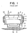
- Fig. 1 is a sectional view showing the conventional electromagnetic induction apparatus of this kind, in which reference numeral 1 designates an electrical coil assembly of an electromagnetic induction apparatus; 2 is an electrically insulating oil; 3 is a tank main body in which the coil assembly 1 is housed together with the insulating oil 2; 31 is a tank side plate constituting one portion of the tank main body 3; 32 is a tank bottom plate constituting one portion of the tank main body 3; 4 are reinforcing members for the tank side plate 31; 5 are sound shield members mounted to the reinforcing members 4; 6 are heavy objects attached to the sound shield members 5; 7 are reinforcing members for the tank bottom plate 32; 8 are electrical bushings connected to the coil assembly 1 mounted on a tank top plate 33; 9 is a floor surface on which the electromagnetic induction apparatus is installed, and 10 are spaces defined between the reinforcing members 7, the tank bottom plate 32 and the floor surface 9.
- the coil assembly 1 of the electromagnetic induction apparatus vibrates in all vertical and horizontal directions due to electromagnetic forces during normal operational conditions of the induction apparatus. Such vibrations are transmitted through the electrical insulating oil 2 to vibrate the tank main body 3, causing noises.
- the sound absorbing members 5 are mounted to the reinforcing member 4 attached to the side plates 31 of the tank main body 3, and heavy objects 6 are additionally attached to the sound absorbing members 5 to improve the sound absorbing function of the sound absorbing members 5.
- a conventional electromagnetic induction apparatus with a sound suppressing arrangement is designed as described above, noises generated due to the vibration of the tank side plate 3 can be effectively reduced by the sound absorbing members 5 attached to the tank side plates 3, but noises generated by the tank bottom plate 32 and radiated from the space 10 defined between the reinforcing members 7, the bottom plate 32 and the floor surface 9 cannot be effectively reduced. Therefore, it has been necessary to provide a large scale sound insulating arrangement such as a sound shield wall or the like around the induction apparatus in order to effectively reduce the noise of the conventional electromagnetic induction apparatus.
- This invention has been made in order to solve the above-mentioned problems of the conventional electromagnetic induction apparatus, and accordingly one object of the present invention is to provide an electromagnetic induction apparatus in which any noise generated by the vibrating induction device is effectively suppressed.
- Another object of the present invention is to provide an electromagnetic induction apparatus with a sound suppressing arrangement in which any noise generated by the vibration of the tank bottom plate and radiated from the spaces formed between the reinforcing members, the bottom plate and the floor surface is significantly suppressed, too.
- Still another object of the present invention is to provide an electromagnetic induction apparatus with a sound suppressing arrangement in which any noise generated by the vibration of the tank bottom plate is insulated.
- a further object of the present invention is to provide an electromagnetic induction apparatus with a sound suppressing arrangement in which any noise generated by the vibration of the tank bottom plate is absorbed.
- the electromagnetic induction apparatus with a sound suppressing arrangement of the present invention comprises a tank main body having a bottom plate and capable of being placed on a floor surface and containing therein an electrical device which vibrates during operation.
- the tank main body is supported by supporting members inserted between the tank bottom plate and the floor surface to define spaces therebetween, and a sound suppressing member is disposed in association with the space defined between the support members and between the tank bottom plate and the floor surface.
- the sound suppressing member may be a sound barrier member closing the space defined between the tank bottom plate and the floor surface or a sound absorbing or suppressing element disposed within the space.
- any noise generated in the space defined between the reinforcing members and the floor surface is directly insulated or suppressed.
- Figs. 2 to 4 illustrate an electromagnetic induction apparatus with a sound suppressing arrangement according to the present invention. It is seen that only a lower portion of the electromagnetic induction apparatus is illustrated for the simplisity of explanation. The other portion of the electromagnetic induction apparatus not illustrated in Figs. 2 to 4 is the same as that shown in Fig. 1 and accordingly, the illustrated electrical induction apparatus is an electrical transformer having an electrical coil assembly similar to the coil assembly 1 shown in Fig. 1.
- the electromagnetic induction apparatus comprises a tank main body 3 having side walls 31, a bottom wall 32 and a top wall 33 (Fig. 1).
- the tank main body 3 contains therein an electrically insulating oil 2 and an electrical device such as an electrical coil assembly 1 immersed in the insulating oil 2 and vibrating during operation.
- the support members 7 are box-like or block-like members attached to the outer (lower) surface of the tank bottom wall 32.
- the electromagnetic induction apparatus comprises a sound barrier member 11 disposed in association with the spaces 10 defined between the support members 7 and between the tank bottom wall 32 and the floor surface 9.
- the sound barrier member 11 is an elongated plate which is secured by welding for example at its upper side edge to the tank side wall 31 to close the spaces 10 against the exterior as best shown in Figs. 3 and 4.
- any noise generated by the vibration of the tank bottom plate 32 due to the vibration of the coil assembly 1 within the tank propagates in the space 10 as shown by arrows and is shielded and confined by the sound barrier member 11 within the spaces 10, so that the leakage of the noise to the exterior from the spaces 10 formed between the tank bottom plate 32 and the floor surface 9 is or significantly reduced.
- FIGs. 2 to 4 employs the sound barrier members 11 by which the noise generated by the tank bottom wall 32 is shielded and confined by the sound shielding members 11 mounted to the tank bottom plate 32 or the tank side plate 31 in the vicinity of the tank bottom plate 32 to close the spaces 10 below the tank bottom wall 32
- a similar sound suppressing effect can also be obtained by inserting a sound absorbing element into the spaces 10 defined between the support members 7 and between the tank bottom wall 32 and the floor surface 9.
- Figs. 5 to 8 illustrate one of such embodiments in which a sound absorbing material 12 in the form of a block of asbestos is inserted into each space 10 defined between the tank bottom wall 32 and the floor surface 9.
- a radiation impedance r4 of the outlet cross-sectional area S1 of the space 10 and a radiation impedance r2 of surface area S2 of the tank bottom wall 32 are connected in series with an acoustic source U, and an acoustic capacitance C of the space 10 and a resistance r3 of the sound absorbing material 12 are connected in parallel to the impedance r1.
- the resistance r3 is connected in parallel with the radiation impedance r1, the resultant impedance of r1 and r2 and the acoustic capacitance C is smaller than that when there is no resistance r3, whereby the sound level at the point X or the noise radiated from the space outlet of the area S1 is decreased.
- the space 10 can resonate with the vibration of the tank bottom plate 32, causing the generated noise to become much larger than that when no resonance occurs.
- the noise can be reduced by inserting a structural member 13 such as shown in Figs. 9 and 10 into each of the spaces 10 formed between the support members 7 and under the tank bottom wall 32.
- the structural element 13 has three vertical rectangular plates 13a and one horizontal rectangular plate 13b supported at the center of the vertical plates 13a to provide a cross-sectional shape of a monogram composed of an "H" and an "I" crossing the horizontal leg of "H".
- the distance of the horizontal plate 13b relative to the tank bottom wall 32 is selected so that no resonace occurs when it is inserted into the space 10.
- the structural element 13 may preferably be attached to the tank bottom wall 32.
- a structural member 14 comprises a plurality of rectangular plates 14a arranged in a plane perpendicular to the longitudinal direction of the structural member 14 and a horizontal plate 14b supported by the plates 14a.
- the horizontal plate 14b is positioned to prevent any resonance within the space 10. It is seen that the vertical plates 14a close the space 10.
- the sound absorbing arrangement for an electromagnetic induction apparatus can suppress any noise generated in the space formed between the tank bottom plate reinforcing members and the floor surface with a simple structure without employing a large scale sound insulating facility such as a sound insulating wall by shielding the above space with a sound shielding member or by disposing a sound supressing element into the space.
Landscapes
- Engineering & Computer Science (AREA)
- Power Engineering (AREA)
- Regulation Of General Use Transformers (AREA)
- Housings And Mounting Of Transformers (AREA)
Applications Claiming Priority (2)
| Application Number | Priority Date | Filing Date | Title |
|---|---|---|---|
| JP4823188A JPH01220809A (ja) | 1988-02-29 | 1988-02-29 | 電磁誘導機器の減音装置 |
| JP48231/88 | 1988-02-29 |
Publications (2)
| Publication Number | Publication Date |
|---|---|
| EP0331008A1 true EP0331008A1 (de) | 1989-09-06 |
| EP0331008B1 EP0331008B1 (de) | 1992-10-21 |
Family
ID=12797666
Family Applications (1)
| Application Number | Title | Priority Date | Filing Date |
|---|---|---|---|
| EP19890103172 Expired EP0331008B1 (de) | 1988-02-29 | 1989-02-23 | Elektromagnetischer Induktionsapparat mit Geräuschunterdrückungsanordung |
Country Status (3)
| Country | Link |
|---|---|
| EP (1) | EP0331008B1 (de) |
| JP (1) | JPH01220809A (de) |
| DE (1) | DE68903230T2 (de) |
Cited By (1)
| Publication number | Priority date | Publication date | Assignee | Title |
|---|---|---|---|---|
| EP2095381B1 (de) | 2006-12-28 | 2016-03-02 | ABB Technology Ltd | Leistungstransformator/-reaktor |
Families Citing this family (4)
| Publication number | Priority date | Publication date | Assignee | Title |
|---|---|---|---|---|
| JP5444644B2 (ja) * | 2008-06-20 | 2014-03-19 | 株式会社明電舎 | 静止誘導機器 |
| JP2013254881A (ja) * | 2012-06-08 | 2013-12-19 | Toshiba Corp | 電気機器 |
| JP6727142B2 (ja) * | 2017-01-13 | 2020-07-22 | 株式会社日立製作所 | 静止誘導電器 |
| JP7232608B2 (ja) * | 2018-10-04 | 2023-03-03 | 株式会社日立製作所 | 静止誘導電器 |
Citations (1)
| Publication number | Priority date | Publication date | Assignee | Title |
|---|---|---|---|---|
| EP0087121A1 (de) * | 1982-02-20 | 1983-08-31 | Hitachi, Ltd. | Anordnung zur Geräuschminderung bei stationären Induktionsapparaten |
-
1988
- 1988-02-29 JP JP4823188A patent/JPH01220809A/ja active Pending
-
1989
- 1989-02-23 DE DE1989603230 patent/DE68903230T2/de not_active Expired - Fee Related
- 1989-02-23 EP EP19890103172 patent/EP0331008B1/de not_active Expired
Patent Citations (1)
| Publication number | Priority date | Publication date | Assignee | Title |
|---|---|---|---|---|
| EP0087121A1 (de) * | 1982-02-20 | 1983-08-31 | Hitachi, Ltd. | Anordnung zur Geräuschminderung bei stationären Induktionsapparaten |
Cited By (1)
| Publication number | Priority date | Publication date | Assignee | Title |
|---|---|---|---|---|
| EP2095381B1 (de) | 2006-12-28 | 2016-03-02 | ABB Technology Ltd | Leistungstransformator/-reaktor |
Also Published As
| Publication number | Publication date |
|---|---|
| EP0331008B1 (de) | 1992-10-21 |
| JPH01220809A (ja) | 1989-09-04 |
| DE68903230D1 (de) | 1992-11-26 |
| DE68903230T2 (de) | 1993-05-19 |
Similar Documents
| Publication | Publication Date | Title |
|---|---|---|
| US3451503A (en) | Sound-reducing housing for alternating current electric apparatus | |
| US8044307B2 (en) | Power transformer/reactor | |
| EP0048990A2 (de) | Schalldämmvorrichtung für einen statischen Induktionsapparat | |
| EP0331008B1 (de) | Elektromagnetischer Induktionsapparat mit Geräuschunterdrückungsanordung | |
| US4054790A (en) | Light fixture | |
| US5184104A (en) | Electromagnetic induction apparatus with a sound suppressing arrangement | |
| US5814761A (en) | Passive EMI dissipation apparatus and method | |
| EP1196930B2 (de) | Schallisolierende vorrichtung für eine induktionsmaschine | |
| KR970032265A (ko) | 전기 음향 변환기 | |
| US4999745A (en) | Electrical equipment chassis unit | |
| JPS6161247B2 (de) | ||
| EP4618117A2 (de) | Transformatoranordnung | |
| JP7232608B2 (ja) | 静止誘導電器 | |
| JPS5834907A (ja) | 防音油入電気機器 | |
| JP2003243855A (ja) | 回路基板の取付け構造 | |
| JPH0516133B2 (de) | ||
| JPS639915A (ja) | 静止誘導電器 | |
| KR860003014Y1 (ko) | 정지유도전기(靜止誘導電器) | |
| JP4427893B2 (ja) | 静止誘導電器の遮音装置 | |
| JPH03120707A (ja) | 静止誘導電器 | |
| JPH0347313Y2 (de) | ||
| JPH06120057A (ja) | チョークコイル実装構造 | |
| JPS5843504A (ja) | 大容量変圧器のタンク | |
| JPH06216557A (ja) | 電磁シールド構造 | |
| JPS59182513A (ja) | 静止誘導電器 |
Legal Events
| Date | Code | Title | Description |
|---|---|---|---|
| PUAI | Public reference made under article 153(3) epc to a published international application that has entered the european phase |
Free format text: ORIGINAL CODE: 0009012 |
|
| AK | Designated contracting states |
Kind code of ref document: A1 Designated state(s): CH DE FR LI SE |
|
| 17P | Request for examination filed |
Effective date: 19890905 |
|
| 17Q | First examination report despatched |
Effective date: 19911204 |
|
| GRAA | (expected) grant |
Free format text: ORIGINAL CODE: 0009210 |
|
| AK | Designated contracting states |
Kind code of ref document: B1 Designated state(s): CH DE FR LI SE |
|
| REF | Corresponds to: |
Ref document number: 68903230 Country of ref document: DE Date of ref document: 19921126 |
|
| ET | Fr: translation filed | ||
| PLBE | No opposition filed within time limit |
Free format text: ORIGINAL CODE: 0009261 |
|
| STAA | Information on the status of an ep patent application or granted ep patent |
Free format text: STATUS: NO OPPOSITION FILED WITHIN TIME LIMIT |
|
| 26N | No opposition filed | ||
| PGFP | Annual fee paid to national office [announced via postgrant information from national office to epo] |
Ref country code: SE Payment date: 19940216 Year of fee payment: 6 |
|
| PGFP | Annual fee paid to national office [announced via postgrant information from national office to epo] |
Ref country code: DE Payment date: 19940224 Year of fee payment: 6 |
|
| PGFP | Annual fee paid to national office [announced via postgrant information from national office to epo] |
Ref country code: FR Payment date: 19940511 Year of fee payment: 6 |
|
| PGFP | Annual fee paid to national office [announced via postgrant information from national office to epo] |
Ref country code: CH Payment date: 19940516 Year of fee payment: 6 |
|
| EAL | Se: european patent in force in sweden |
Ref document number: 89103172.6 |
|
| PG25 | Lapsed in a contracting state [announced via postgrant information from national office to epo] |
Ref country code: SE Effective date: 19950224 |
|
| PG25 | Lapsed in a contracting state [announced via postgrant information from national office to epo] |
Ref country code: LI Effective date: 19950228 Ref country code: CH Effective date: 19950228 |
|
| PG25 | Lapsed in a contracting state [announced via postgrant information from national office to epo] |
Ref country code: FR Effective date: 19951031 |
|
| PG25 | Lapsed in a contracting state [announced via postgrant information from national office to epo] |
Ref country code: DE Effective date: 19951101 |
|
| EUG | Se: european patent has lapsed |
Ref document number: 89103172.6 |
|
| REG | Reference to a national code |
Ref country code: FR Ref legal event code: ST |