EP0331106B1 - Gepäckträger mit Stütz- und Verbindungsmitteln - Google Patents
Gepäckträger mit Stütz- und Verbindungsmitteln Download PDFInfo
- Publication number
- EP0331106B1 EP0331106B1 EP89103494A EP89103494A EP0331106B1 EP 0331106 B1 EP0331106 B1 EP 0331106B1 EP 89103494 A EP89103494 A EP 89103494A EP 89103494 A EP89103494 A EP 89103494A EP 0331106 B1 EP0331106 B1 EP 0331106B1
- Authority
- EP
- European Patent Office
- Prior art keywords
- bar
- luggage
- bar assembly
- assembly according
- upright
- Prior art date
- Legal status (The legal status is an assumption and is not a legal conclusion. Google has not performed a legal analysis and makes no representation as to the accuracy of the status listed.)
- Expired
Links
- 230000008878 coupling Effects 0.000 title claims description 23
- 238000010168 coupling process Methods 0.000 title claims description 23
- 238000005859 coupling reaction Methods 0.000 title claims description 23
- 230000007935 neutral effect Effects 0.000 claims description 2
- 230000013011 mating Effects 0.000 claims 2
- 230000014759 maintenance of location Effects 0.000 description 3
- 230000037431 insertion Effects 0.000 description 2
- 238000003780 insertion Methods 0.000 description 2
- 238000009434 installation Methods 0.000 description 1
- 230000000670 limiting effect Effects 0.000 description 1
- 210000002445 nipple Anatomy 0.000 description 1
- 238000010008 shearing Methods 0.000 description 1
Images

Classifications
-
- B—PERFORMING OPERATIONS; TRANSPORTING
- B60—VEHICLES IN GENERAL
- B60R—VEHICLES, VEHICLE FITTINGS, OR VEHICLE PARTS, NOT OTHERWISE PROVIDED FOR
- B60R9/00—Supplementary fittings on vehicle exterior for carrying loads, e.g. luggage, sports gear or the like
- B60R9/04—Carriers associated with vehicle roof
- B60R9/058—Carriers associated with vehicle roof characterised by releasable attaching means between carrier and roof
Definitions
- the present invention relates to a luggage bar assembly with supporting and coupling means.
- Luggage bars currently use complicated and expensive support and coupling means which should allow the bar to be adapted to the different kinds of motor vehicle, especially motor cars, which differ not only in their dimensions but also for the manner in which said coupling means are fixed to the bodywork.
- EP-A-0 105 849 which shows the features of the first part of claim 1 discloses a load carrier with the object of being suitable for use on any type of vehicle, i.e. with or without a so called rain fillet provided on the roof of the vehicle.
- Such load carrier comprises a girder extending across the body of a vehicle and being provided near its end with a support adapted to be placed on the body and with a clamping member movable with respect to the support.
- a mechanically complicated coupling system exists whereby the clamping member is movably coupled with an intermediate element which is pivotable with respect to support, whilst a stretching element in form of a locking bolt is operative between the support or the girder respectively and the clamping member.
- the aim of the present invention is to radically simplify known luggage bars by significantly improving their functionality and allowing, at the same time, to provide structures adaptable to different types of motor vehicle simply by replacing, where necessary, structure elements which differ in dimensions of configuration.
- the luggage bar assembly according to the present invention is therefore of the dedicated type, as it is constituted by elements which are sized and preset for uniform series of motor vehicles and can be adapted to other series by replacing already-preset structure elements.
- the present invention relates to a luggage bar assembly as defined in the appended claims.
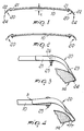
- 10 indicates the luggage bar, termed "carryall"
- 20 indicates the uprights provided at its ends and intended to support and couple said bar to the roof of the motor vehicle.
- each of the uprights 20 is constituted by a profiled element with a channel-like portion 21 intended to fit over the corresponding end of the bar 10 and by a flattened coupling portion 22 stiffened by ridges 23 and ending with a wing 24 folded substantially at right angle and adapted to cooperate with a corresponding undercut SQ of the vehicle's bodywork.
- a locking bolt 25 co-operates with the channel-like portion 21 of the upright and passes through a hole 26 of the bar; said bolt is sized so as to absorb the flexing and shearing stresses discharged on each upright 20 by the bar 10.
- one or both upright connecting bolts 25 are slackened, allowing said uprights to be divaricated by rotating them, in the vertical plane containing the axis of the bar, around the corner s of the terminal edge of the upright.
- the bolts 25 are slackened so as to allow each upright to be divaricated by an amount Y sufficient to allow the wing 24 to pass beyond the undercut SQ, allowing the structural assembly to be located on the roof of the vehicle or to be removed therefrom.
- the bolt is successively tightened to cause a reverse rotation of the uprights, the wings 24 whereof engage the undercut SQ.
- the camber of the bar 10 furthermore gives a negative pre-deformation to the bar for compensating its deformation when loaded, thus preventing, in such conditions, the loosening of the locking action on the uprights 20.
- the variated embodiment of figure 5 differs in that the upright 20a supports the bar 10 by engaging its lower surface, and the upright advantageously has, in this case, a transverse ridge 30 which defines the axis of relative rotation between the bar and the upright during the slackening or tightening of the bolt 25.
- the bar 10 (see fig. 6) can be stiffened by means of a tension element 31 arranged in its interior, which by virtue of the bar's camber arranges itself at least partially below the neutral axis of said bar in a position suitable to absorb the traction stresses arising from the flexing of the bar when it is loaded.
- the tension element 31 can be advantageously pretensioned, for example by means of a bolt 32 which engages the threaded end 33 of the tension element; the other end of the tension element is stably coupled to the corresponding end of the bar by means of a nipple 34.
- the solution shown in figures 7 to 10 relates to a different embodiment of the uprights 20 adapted to support coupling portions 240 which are removable with respect to said upright; the coupling portions 240 are replaceable with others with different profiles in relation to the type of vehicle on which the bar is mounted.
- a base plate 201 is defined at the lower end of each upright, for example by folding at right angle at least one wall of said upright, and has at least one opening 202 and at least one protruding lug 203 which co-operate by insertion coupling with a tab 241 and respectively with a slot 242 of the corresponding coupling portion 240.
- the opening 202 and the tab 241 have a substantially T-shaped profile to connect by mutual insertion coupling.
Landscapes
- Engineering & Computer Science (AREA)
- Mechanical Engineering (AREA)
- Body Structure For Vehicles (AREA)
Claims (10)
Applications Claiming Priority (2)
| Application Number | Priority Date | Filing Date | Title |
|---|---|---|---|
| IT67163/88A IT1219066B (it) | 1988-03-02 | 1988-03-02 | Struttura di barra portabagagli e relativi mezzi di supporto e vincolo all'autoveicolo |
| IT6716388 | 1988-03-02 |
Publications (3)
| Publication Number | Publication Date |
|---|---|
| EP0331106A2 EP0331106A2 (de) | 1989-09-06 |
| EP0331106A3 EP0331106A3 (en) | 1989-12-06 |
| EP0331106B1 true EP0331106B1 (de) | 1992-04-22 |
Family
ID=11300122
Family Applications (1)
| Application Number | Title | Priority Date | Filing Date |
|---|---|---|---|
| EP89103494A Expired EP0331106B1 (de) | 1988-03-02 | 1989-02-28 | Gepäckträger mit Stütz- und Verbindungsmitteln |
Country Status (3)
| Country | Link |
|---|---|
| EP (1) | EP0331106B1 (de) |
| DE (1) | DE68901282D1 (de) |
| IT (1) | IT1219066B (de) |
Families Citing this family (2)
| Publication number | Priority date | Publication date | Assignee | Title |
|---|---|---|---|---|
| SE470181B (sv) * | 1991-09-09 | 1993-11-29 | Thule Ind Ab | Anordning vid lastbärarfot |
| CN116605147B (zh) * | 2023-05-10 | 2025-11-07 | 磐吉奥科技股份有限公司 | 汽车用行李支架及汽车 |
Family Cites Families (5)
| Publication number | Priority date | Publication date | Assignee | Title |
|---|---|---|---|---|
| SE352031B (de) * | 1970-01-23 | 1972-12-18 | Saab Scania Ab | |
| NL8203504A (nl) * | 1982-09-08 | 1984-04-02 | Thule Ind Ab | Lastdrager. |
| DE8231083U1 (de) * | 1982-11-06 | 1987-03-12 | Goldbecker, Manfred, 4803 Steinhagen | Autodachkoffer |
| DE3315555A1 (de) * | 1983-04-29 | 1984-10-31 | Alois 8064 Unterzeitlbach Kauf | Trageeinrichtung zum transport von dachlasten fuer kraftfahrzeuge, insbesondere personenkraftwagen ohne dachrinnen |
| DE3406149A1 (de) * | 1984-02-21 | 1985-08-22 | Heinz Kettler Metallwarenfabrik Gmbh & Co, 4763 Ense | Dachgepaecktraeger |
-
1988
- 1988-03-02 IT IT67163/88A patent/IT1219066B/it active
-
1989
- 1989-02-28 EP EP89103494A patent/EP0331106B1/de not_active Expired
- 1989-02-28 DE DE8989103494T patent/DE68901282D1/de not_active Expired - Fee Related
Also Published As
| Publication number | Publication date |
|---|---|
| IT8867163A0 (it) | 1988-03-02 |
| EP0331106A2 (de) | 1989-09-06 |
| DE68901282D1 (de) | 1992-05-27 |
| IT1219066B (it) | 1990-04-24 |
| EP0331106A3 (en) | 1989-12-06 |
Similar Documents
| Publication | Publication Date | Title |
|---|---|---|
| EP3863875B1 (de) | Festzurranordnung für laderaumabdeckung | |
| US5848743A (en) | Vehicle roof rack | |
| US5472256A (en) | Latching crossbar apparatus for truck bed covers | |
| US6971563B2 (en) | Stationary ladder rack with double wedge interlocking mechanism | |
| US5395024A (en) | Supporting structure for a roof rack | |
| EP0640045B1 (de) | Dachgepäckkoffer | |
| CA3100526C (en) | Low profile toolbox and headache rack mounting bracket | |
| US8272683B2 (en) | Vehicle roof assembly | |
| US20190381959A1 (en) | Rack of Unitary One-Piece Construction | |
| US4065041A (en) | Wrap-around roof rack | |
| EP0331106B1 (de) | Gepäckträger mit Stütz- und Verbindungsmitteln | |
| US5984155A (en) | Utility bar assemblies for a roof rack | |
| CA1289164C (en) | Exterior extension for a truck cab | |
| US5857735A (en) | Self-supporting roof with built-in fittings directly mountable upon vehicle roofs | |
| US4902065A (en) | Roof bow support for covers on truck beds | |
| US4277098A (en) | Foldable truck cap assembly | |
| US4497425A (en) | Carrier arrangement | |
| US20250282298A1 (en) | Vehicle equipment mount | |
| WO2023018826A1 (en) | Adjustable cargo accessory | |
| HU224735B1 (en) | Suspension of trace-hook for motor vehicle | |
| EP3858678A1 (de) | Querträger und kupplungselement für einen querträger | |
| EP0258193A2 (de) | Lastverankerungsanordnung | |
| WO2022125065A1 (en) | I-beam clamp | |
| CN111409562A (zh) | 一种汽车车顶行李架结构 | |
| EP0688697B1 (de) | Selbsttragender Dachhimmel mit Aufsatzstücken für die unmittelbare Montage auf Kraftfahrzeugdächern |
Legal Events
| Date | Code | Title | Description |
|---|---|---|---|
| PUAI | Public reference made under article 153(3) epc to a published international application that has entered the european phase |
Free format text: ORIGINAL CODE: 0009012 |
|
| AK | Designated contracting states |
Kind code of ref document: A2 Designated state(s): CH DE FR LI SE |
|
| PUAL | Search report despatched |
Free format text: ORIGINAL CODE: 0009013 |
|
| AK | Designated contracting states |
Kind code of ref document: A3 Designated state(s): CH DE FR LI SE |
|
| 17P | Request for examination filed |
Effective date: 19891230 |
|
| 17Q | First examination report despatched |
Effective date: 19901127 |
|
| GRAA | (expected) grant |
Free format text: ORIGINAL CODE: 0009210 |
|
| AK | Designated contracting states |
Kind code of ref document: B1 Designated state(s): CH DE FR LI SE |
|
| PG25 | Lapsed in a contracting state [announced via postgrant information from national office to epo] |
Ref country code: SE Effective date: 19920422 |
|
| REF | Corresponds to: |
Ref document number: 68901282 Country of ref document: DE Date of ref document: 19920527 |
|
| ET | Fr: translation filed | ||
| PLBE | No opposition filed within time limit |
Free format text: ORIGINAL CODE: 0009261 |
|
| STAA | Information on the status of an ep patent application or granted ep patent |
Free format text: STATUS: NO OPPOSITION FILED WITHIN TIME LIMIT |
|
| 26N | No opposition filed | ||
| PGFP | Annual fee paid to national office [announced via postgrant information from national office to epo] |
Ref country code: CH Payment date: 19970131 Year of fee payment: 9 |
|
| PGFP | Annual fee paid to national office [announced via postgrant information from national office to epo] |
Ref country code: DE Payment date: 19970215 Year of fee payment: 9 |
|
| PGFP | Annual fee paid to national office [announced via postgrant information from national office to epo] |
Ref country code: FR Payment date: 19970221 Year of fee payment: 9 |
|
| PG25 | Lapsed in a contracting state [announced via postgrant information from national office to epo] |
Ref country code: LI Free format text: LAPSE BECAUSE OF NON-PAYMENT OF DUE FEES Effective date: 19980228 Ref country code: FR Free format text: THE PATENT HAS BEEN ANNULLED BY A DECISION OF A NATIONAL AUTHORITY Effective date: 19980228 Ref country code: CH Free format text: LAPSE BECAUSE OF NON-PAYMENT OF DUE FEES Effective date: 19980228 |
|
| REG | Reference to a national code |
Ref country code: CH Ref legal event code: PL |
|
| PG25 | Lapsed in a contracting state [announced via postgrant information from national office to epo] |
Ref country code: DE Free format text: LAPSE BECAUSE OF NON-PAYMENT OF DUE FEES Effective date: 19981103 |
|
| REG | Reference to a national code |
Ref country code: FR Ref legal event code: ST |