EP0331166B1 - Verfahren zum Trennen von asbestenthaltendem Material und Verhindern von schwebendem Staub - Google Patents
Verfahren zum Trennen von asbestenthaltendem Material und Verhindern von schwebendem Staub Download PDFInfo
- Publication number
- EP0331166B1 EP0331166B1 EP19890103659 EP89103659A EP0331166B1 EP 0331166 B1 EP0331166 B1 EP 0331166B1 EP 19890103659 EP19890103659 EP 19890103659 EP 89103659 A EP89103659 A EP 89103659A EP 0331166 B1 EP0331166 B1 EP 0331166B1
- Authority
- EP
- European Patent Office
- Prior art keywords
- asbestos
- containing material
- water
- nozzles
- preceeding
- Prior art date
- Legal status (The legal status is an assumption and is not a legal conclusion. Google has not performed a legal analysis and makes no representation as to the accuracy of the status listed.)
- Expired - Lifetime
Links
Images

Classifications
-
- E—FIXED CONSTRUCTIONS
- E04—BUILDING
- E04G—SCAFFOLDING; FORMS; SHUTTERING; BUILDING IMPLEMENTS OR AIDS, OR THEIR USE; HANDLING BUILDING MATERIALS ON THE SITE; REPAIRING, BREAKING-UP OR OTHER WORK ON EXISTING BUILDINGS
- E04G23/00—Working measures on existing buildings
-
- B—PERFORMING OPERATIONS; TRANSPORTING
- B05—SPRAYING OR ATOMISING IN GENERAL; APPLYING FLUENT MATERIALS TO SURFACES, IN GENERAL
- B05B—SPRAYING APPARATUS; ATOMISING APPARATUS; NOZZLES
- B05B1/00—Nozzles, spray heads or other outlets, with or without auxiliary devices such as valves, heating means
- B05B1/14—Nozzles, spray heads or other outlets, with or without auxiliary devices such as valves, heating means with multiple outlet openings; with strainers in or outside the outlet opening
-
- B—PERFORMING OPERATIONS; TRANSPORTING
- B05—SPRAYING OR ATOMISING IN GENERAL; APPLYING FLUENT MATERIALS TO SURFACES, IN GENERAL
- B05B—SPRAYING APPARATUS; ATOMISING APPARATUS; NOZZLES
- B05B15/00—Details of spraying plant or spraying apparatus not otherwise provided for; Accessories
- B05B15/14—Arrangements for preventing or controlling structural damage to spraying apparatus or its outlets, e.g. for breaking at desired places; Arrangements for handling or replacing damaged parts
- B05B15/16—Arrangements for preventing or controlling structural damage to spraying apparatus or its outlets, e.g. for breaking at desired places; Arrangements for handling or replacing damaged parts for preventing non-intended contact between spray heads or nozzles and foreign bodies, e.g. nozzle guards
-
- B—PERFORMING OPERATIONS; TRANSPORTING
- B05—SPRAYING OR ATOMISING IN GENERAL; APPLYING FLUENT MATERIALS TO SURFACES, IN GENERAL
- B05B—SPRAYING APPARATUS; ATOMISING APPARATUS; NOZZLES
- B05B3/00—Spraying or sprinkling apparatus with moving outlet elements or moving deflecting elements
- B05B3/02—Spraying or sprinkling apparatus with moving outlet elements or moving deflecting elements with rotating elements
- B05B3/025—Rotational joints
- B05B3/026—Rotational joints the fluid passing axially from one joint element to another
-
- B—PERFORMING OPERATIONS; TRANSPORTING
- B05—SPRAYING OR ATOMISING IN GENERAL; APPLYING FLUENT MATERIALS TO SURFACES, IN GENERAL
- B05B—SPRAYING APPARATUS; ATOMISING APPARATUS; NOZZLES
- B05B9/00—Spraying apparatus for discharge of liquids or other fluent material, without essentially mixing with gas or vapour
- B05B9/01—Spray pistols, discharge devices
-
- B—PERFORMING OPERATIONS; TRANSPORTING
- B08—CLEANING
- B08B—CLEANING IN GENERAL; PREVENTION OF FOULING IN GENERAL
- B08B3/00—Cleaning by methods involving the use or presence of liquid or steam
- B08B3/02—Cleaning by the force of jets or sprays
- B08B3/026—Cleaning by making use of hand-held spray guns; Fluid preparations therefor
- B08B3/028—Spray guns
-
- B—PERFORMING OPERATIONS; TRANSPORTING
- B09—DISPOSAL OF SOLID WASTE; RECLAMATION OF CONTAMINATED SOIL
- B09B—DISPOSAL OF SOLID WASTE NOT OTHERWISE PROVIDED FOR
- B09B3/00—Destroying solid waste or transforming solid waste into something useful or harmless
- B09B3/70—Chemical treatment, e.g. pH adjustment or oxidation
-
- E—FIXED CONSTRUCTIONS
- E04—BUILDING
- E04G—SCAFFOLDING; FORMS; SHUTTERING; BUILDING IMPLEMENTS OR AIDS, OR THEIR USE; HANDLING BUILDING MATERIALS ON THE SITE; REPAIRING, BREAKING-UP OR OTHER WORK ON EXISTING BUILDINGS
- E04G23/00—Working measures on existing buildings
- E04G23/08—Wrecking of buildings
-
- B—PERFORMING OPERATIONS; TRANSPORTING
- B09—DISPOSAL OF SOLID WASTE; RECLAMATION OF CONTAMINATED SOIL
- B09B—DISPOSAL OF SOLID WASTE NOT OTHERWISE PROVIDED FOR
- B09B2101/00—Type of solid waste
- B09B2101/35—Asbestos
-
- Y—GENERAL TAGGING OF NEW TECHNOLOGICAL DEVELOPMENTS; GENERAL TAGGING OF CROSS-SECTIONAL TECHNOLOGIES SPANNING OVER SEVERAL SECTIONS OF THE IPC; TECHNICAL SUBJECTS COVERED BY FORMER USPC CROSS-REFERENCE ART COLLECTIONS [XRACs] AND DIGESTS
- Y10—TECHNICAL SUBJECTS COVERED BY FORMER USPC
- Y10T—TECHNICAL SUBJECTS COVERED BY FORMER US CLASSIFICATION
- Y10T83/00—Cutting
- Y10T83/04—Processes
- Y10T83/0591—Cutting by direct application of fluent pressure to work
Definitions
- the invention relates to a process for separation, or stripping, of an asbestos-containing material such as asbestos sprayed to the surface of a ceiling or wall of a building, etc. from a surface while preventing the release of the separated asbestos-containing material as a fine dust into the atmosphere.
- asbestos fibers may fly off or are suspended in air when the surface spray-coated with asbestos is vibrated or when an object collides against such a surface or when the binder used in the coating is deteriorated with time. This will do harm to the health of human bodies. It is thus urgently required to remove the spayed asbestos.
- the removal of the sprayed asbestos was made by a method wherein workers wearing dust respirators and dustproof clothes strip the sprayed asbestos layer by rod-type scrapers or wire brushes in a sealed wookroom prepared for such a removal operation.
- the method of physical removal of the asbestos may be effective as a permanent solution.
- the manual removal of asbestos by use of rod-type scrapers or wire brushes is laborious and leads to high working expenses.
- this method has the problem that the asbestos fibers generated in the removal operation are suspended in air for a long time, and that the workroom must be sealed for a long time. Forced removal of the asbestos fibers requires the use of HEPA filters ( h igh e fficiency p article air filter) and a large-capacity dust collector, leading to extremely high working expenses.
- the manual removal of asbestos by the workers has the problem that many portions of asbestos are usually left unstripped, particularly at narrow areas near corners or the existing piping, and the portions of asbestos left unstripped may scale off later.
- a dust collector is used, a small amount of the asbestos fibers separated from the original surface may remain in the air or accumulate at the corners of the floor, since asbestos fibers are very difficult to collect.
- EP-A1-0200858 discloses a method for removal of asbestos from a wall surface wherein a water gun with a revolving nozzle head is used. High-pressurized water is jetted to the wall, so that the energy of the water removes the asbestos while asbestos particles are bound to the water.
- a process for separation of an asbestos-containing material from a surface to which the asbestos-containing material is adhered while preventing release into the atmosphere of the separated asbestos-containing material as a fine dust comprising the following combination of steps: disposing a polymeric water absorbent on a floor surface facing the surface from which the asbestos-containing material is separated, and jetting pressurized water from a nozzle or a plurality of nozzles to an exposed surface of said asbestos-containing material at a pressure of at least 78,4 bar (80 kg/cm2), to thereby wet and separate from the surface the asbestos-containing material by application thereto of energy possessed by the jetted flow of pressurized water and collecting and disposing of said separated wet asbestos-containing material and any of said jetted water that has fallen to the floor surface together with the polymeric water absorbent.
- a further effect on the prevention of the floating of dust of the asbestos-containing material is obtained by preliminary wetting the surface to which the asbestos-containing material is adhered.
- the asbestos-containing material may be pretreated by first spraying an initial quantity of water thereto, and allowing 4 to 5 seconds to elapse before applying said pressurized water flow.
- the pressurized water is jetted substantially in a mist form to an exposed surface of said asbestos-containing material, thereby causing asbestos to adhere to the particles of the mist and fall to the floor surface together with the particles of the mist.
- the water in this process is supplied preferably at a pressure of at least 490 bar (500 kg/cm2) and at a volumetric flow rate of 3 to 12 liters/min. to said nozzles.
- the water is supplied at a pressure of at least 686 bar (700 kg/cm2) and at a volumetric flow rate of 3 to 12 liters/min. to said nozzles for thereby jetting said high pressure water from said nozzles against said surface.
- a sheet of retaining material may be applied to enclose a space containing the surface from which the asbestos-containing material is to be separated.It is also preferred to adhere the polymeric water absorbent material to a base sheet spread over said floor surface or to distribute said polymeric water absorbent material at a rate of 30 g/m2 to 1000 g/m2 on the floor surface or the base sheet.
- the asbestos-containing material is separated, or stripped, from the surface to which the material is adhering, by the energy of pressurized water at a pressure of at least 78,4 bar (80 kg/cm2 ⁇ G).
- This process is therefore more efficient, as compared with the conventional manual work using tools such as rod-type scrapers. It may be contemplated to jet the pressurized water from a single nozzle. In that case, however, the layer of the asbest coating is removed through cutting of the layer, so that large lumps of the coating will fall to the floor causing a severe re-floating of the asbestos fibers.
- the use of a plurality of nozzles ensures sequential stripping of small portions of the layer of the asbestos coating, resulting in less re-floating of dust accompanying the falling of the stripped portions of the layer.
- the use of a plurality of nozzles enables separation of the asbestos coating at a multiplicity of points, whereby separation efficiency is further enhanced.
- the invention is characterized by the separation of the asbestos-containing material by use of water. Therefore, the asbestos fibers fall to the floor while being wetted with water. As a result, the re-floating of the asbestos fiber upon the falling thereof is substantially prevented. Further, the jetting of pressurized water from the plurality of nozzles ensures that the separation of the asbestos-containing material is effected by the action of the sum total of hydraulic energy supplied from each nozzle on the object surface. Therefore, the quantity of water required per nozzle is small, and it is possible to cause the pressurized water jetted from each nozzle to collide against the surface in a mist form.
- the object surface is constantly wetted uniformly while the separation of the asbestos-containing material is carried out, whereby the above-mentioned effect is developed.
- the particles of the mist soon falls to the floor, so that the interior of the workroom is soon made clean, and the asbestos fibers fallen to the floor together with water are caught by the water-asbestos slurry already in a wet state, without re-floating.
- the slurry accumulating on the floor during or after the separating operation is in the wet state when collected for removal by an appropriate cleaner or shovels or scoops, and the collecting and removing operation is extremely easy to perform without any floating or scattering of the matter to be collected.
- an asbestos-containing material is separated, or stripped, from the substrate surface to which the material is adhered.
- the asbestos-containing material is a mixture of asbestos, such as crysotile, amosite, crocidolite (blue asbestos), etc. with a binder such as Portland cement, whereas the substrate surface is a surface of veneer plywood, concrete (mortar), metallic plate or the like.
- a stripping machine (stripping gun) having a plurality of nozzles for jetting pressurized water is prepared.
- Pressurized water is led from a water tank to the nozzle head of the stripping machine by a high-pressure pump, and is jetted from each nozzle to the object surface.
- the pressure of the pressurized water is at least 78,4 bar, preferably at least 490 bar, more preferably at least 784,5 bar.
- the number of the nozzles may be any number greater than one, but a greater number is generally more preferable, from the viewpoint of working efficiency.
- the nozzle head may be non-rotatably fixed to the stripping machine, or may be simply rotated on an axis of rotation in the stripping machine.
- the nozzle head is revolved round the axis of rotation while rotating on its own axis. The most suitable type of stripping machine such as this will be described later.
- a sealed workroom is preliminarily formed by enclosing the object surface of separation with a sheet of polyvinyl chloride or the like so as to prevent the flying-off of the asbestos fibers, and the operation is carried out in the sealed workroom.
- the sheet is laid also over the floor surface.
- the object surface is preliminarily wetted with a liquid, preferably, water.
- a liquid preferably, water.
- a liquid preferably, water.
- sprinkling of water can be performed by spraying water from a spray gun or from the stripping machine, described later, by spacing the stripping machine apart from the object surface. After water sprinkling, a period of time of about 4 to 5 seconds is taken, before starting the next operation.
- Other liquid than water may be used for wetting. It may be contemplated, as another means of prevention of the flying-off of fine asbestos fibers, to consolidate preliminarily the object surface by use of a resin or the like, but this approach is inadvantageous because of the high material cost.
- the total quantity of the pressurized water jetted depends on the pressure of water and the number of nozzles. Where the water pressure is at least 686,5 bar, the nozzle diameter is 0.05 to 0.5 mm and the number of nozzles is at least 5, a total water quantity of 3 to 12 l/min is suitable. If the water quantity is less than 3 l/min, energy for stripping is not sufficient, whereas if the water quantity is more than 12 l/min, the reaction exerted on the operator holding the stripping machine is so great that the operator cannot endure the reaction.
- a water quantity of more than 12 l/min can, naturally, be adopted when the stripping machine is electrically or mechanically driven along a movable base.Under these conditions, the pressurized water is ejected in a mist form from each nozzle, to produce the above-mentioned effect.
- the stripping operation is carried out with the nozzle head at a distance of about 3 to 50 cm from the object surface.
- the floor surface is preliminarily scattered with a polymeric absorbent conventionally used in paper diapers and the like, for instance, starch, acrylic or polyvinyl alcohol based absorbents, which are known.
- the polymeric absorbent is generally available in a powdery form. Scattering of the polymeric absorbent powder may be carried out by simply sprinkling the powder to the floor or, if desired, by adhering the powder to a carrier base, for instance, a nonwoven fabric and spreading the thus obtained sheet over the floor.
- the amount of the polymeric absorbent scattered is preferably 30 g to 1 kg per m2 of the floor surface.
- the separating or stripping operation When the separating or stripping operation is conducted in the presence of the polymeric absorbent, jetted water falls directly to the floor surface, or the mist formed slowly falls to the floor surface, whereupon the falling water and asbestos falling together with the watering are prevented from forming a slurry matter but are converted into dry and crumbling deposits by the action of the polymeric absorbent.
- the deposits are scooped at a suitable time by shovels or scoops, put into a container such as a plastic bag or a sealed metallic container, which is fed out of the sealed workroom.
- the deposits thus removed from the workroom are then stirred and mixed with Portland cement, sand or the like in the exterior, for solidification.
- the solidifying operation may be carried out in the sealed workroom. After the solidification, the solidified waste is burried underground, deeper than 2 m below the ground.
- the worker wears a dust respirator and dustproof clothing.
- the absorption of water by the polymeric absorbent as mentioned above makes it easy for the workers wearing the dustproof clothing (foot covers, also) to walk in the workroom, unlike in the case of the slurry being formed on the floor.
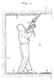
- FIGURE 1 An embodiment of the operation is shown in FIGURE 1.
- sprayed asbestos 2 is adhered to the ceiling substrate 1, and the operation is carried out in a sealed workroom 4 formed by laying a polyvinyl chloride sheet 3 on the walls and the floor, exclusive of the ceiling surface.
- a pressurized water jetting gun G Also shown are a scattered polymeric absorbent 5, and fallen matter 6.
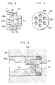
- FIGURE 2 A preferred example of the pressurized water jetting gun is shown in FIGURE 2 and the latter figures.
- a holder 10 of the stripping gun G is of substantially circular tubular form.
- the holder 10 has a front portion 10A and a rear portion 10B connected to each other by bolts 12 so that the holder can be split into the front and rear portions at the time of repair.
- a handle 14 is provided on the lower side of the front portion 10A, in a body with the portion 10A.
- a revolving driven gear 16 is disposed so that as to be rotatable around an axis through the functions of bearings 18A, 18B.
- a liquid feed pipe 20 is supported on the driven gear 16 through bearings 22, 24, with the axis C2 of the pipe 20 deviated from the axis C1 of the holder 10 by, for example, 5 mm.
- An attachment 26 is fitted integrally to a front portion of the liquid feed pipe 20 through a thrust bearing 28.
- a nozzle head 30, which will be described in detail below, is fitted integrally to the attachment 26, coaxially with the axis C2.
- the rear end of the liquid feed pipe 20 is connected to a flexible shaft 32, which is connected to an external pump (not shown) for pressurized water W through a spherical seat 20a.
- Numeral 34 denotes a joint retainer.
- a rear portion of the flexible shaft 32 is fixed by a bush 38 and a fixing nut 40 to a protective pipe 36, which is fitted to the rear portion 10B of the holder 10.
- Numeral 42 denotes an air motor with air Ai as a drive source.
- the air motor 42 is held by the right hand, whereas the handle 14 is held by the left hand, to support the entire body of the machine.
- the air motor 42 has a switch 44, and is mounted on the protective pipe 36 by a mount bracket 46.
- a cavity 48 is formed between the front portion 10A and the rear portion 10B of the holder 10.
- a driving gear 50 which is rotatably supported by bearings 52, 54.
- An output shaft of the air motor 42 and the driving gear 50 are connected to each other by a connecting rod 56, and the driving gear 50 is engaged with the driven gears 16.
- the front portion of the holder 10 is covered by a flexible cover 58 made of rubber or the like, for protection from spattered asbestos fibers, and the nozzle head 30 is also protected by a cover 60.
- the nozzle head 30 is caused to revolve round the axis C1 while rotating on its own axis, preferably at 800 to 4000 rpm. Following up to the revolution round the axis C1, a front portion of the flexible shaft 32 is rotated while being deflected. The swing is absorbed by the bearings 22, 24.
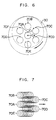
- the nozzle head 30 is provided with a plurality of nozzles 70A, 70B ..., for instance, seven nozzles, as shown in FIGURES 3 and 4.
- one nozzle is provided at the center, and six nozzles are arranged around the central nozzle at an angular pitch of 60°.
- the nozzle head 30 is provided in the center thereof with an inlet hole 71 communicating with the liquid feed pipe 20. From an intermediate portion of the inlet hole 71, connecting holes 72 are extended radially, which communicate with the nozzles 70A, 70B ... through respective introduction holes 73.
- the number of the nozzles may be more than 7.
- the diameter D of the nozzle chip 70a is set to a small value, for instance, 0.15 mm, and the tip thereof is gradually enlarged at a diverging taper angle ⁇ of 25 to 55°, preferably 35 to 45°.
- the pressure of pressurized water fed to each of the nozzles 70A, 70B, ... is preferably at least 784 bar, more preferably at least 980 bar.
- a construction may be adopted wherein the nozzle head 30 is provided with one or a plurality of curtain nozzles 74 in the angle range of, for instance, 15 to 65° from the center axis of the nozzle head 30, and the pressurized water is jetted in a mist form also from the curtain nozzles 74 while the nozzle head 30 is rotated.
- the pressurized water is jetted in a mist form also from the curtain nozzles 74 while the nozzle head 30 is rotated.
- the presence of the certain of mist prevents the asbestos fibers from flying off outward from the object surface. Even if the asbestos fibers fly out of the curtain, the asbestos fibers are wetted in the curtain, resulting in a greater effect on the prevention of re-floating of the asbestos fibers fallen to the floor.
- the operation was performed by the two workers wearing dustproof clothing, dust respirators, goggles, foot covers and gloves, in a workroom formed by laying a polyvinyl chloride sheet, 0.15 mm thick, on the floor and the walls.
- One of the two workers served as an assistant for floor cleaning or the like.
- the working efficiency was as high as 20 to 30 min per 10 m2, and satisfactory removal of the sprayed asbestos was accomplished even for the ceiling portions behind electric wiring.
- the asbestos dust concentration in the workroom was increased during the operation to 6 times the initial value. After 15 min, however, the dust concentration was lowered to a value substantially equal to the initial value, that is, the interior of the wookroom became clean. It is considered that the large amount of mist, which was generated during the operation, fell to the floor together with the asbestos dust.
- the asbestos dust concentration was increased during the operation to 23 times the initial value. Even after 1 hour, the dust concentration was as high as 9 times the initial value. In addition, floating of dust of the asbestos fallen to the floor was visually confirmed as the worker walked. Collection of asbestos was achievable by use of shovels or scoops for part of the fallen asbestos, but the collection of the residual part (one fifth of the total amount of the fallen asbestos) required the use of a dust collector.
Landscapes
- Engineering & Computer Science (AREA)
- Architecture (AREA)
- Chemical & Material Sciences (AREA)
- Chemical Kinetics & Catalysis (AREA)
- Electrochemistry (AREA)
- Mechanical Engineering (AREA)
- Civil Engineering (AREA)
- Structural Engineering (AREA)
- Health & Medical Sciences (AREA)
- General Chemical & Material Sciences (AREA)
- General Health & Medical Sciences (AREA)
- Toxicology (AREA)
- Environmental & Geological Engineering (AREA)
- Working Measures On Existing Buildindgs (AREA)
- Processing Of Solid Wastes (AREA)
- Cleaning By Liquid Or Steam (AREA)
- Cleaning In General (AREA)
- Control And Other Processes For Unpacking Of Materials (AREA)
Claims (11)
- Verfahren zum Trennen asbesthaltigen Materials von einer Oberfläche, an der es anhaftet, wobei verhindert wird, daß das abgetrennte asbesthaltige Material als feiner Staub in die Umgebung entweicht, gekennzeichnet durch folgende Kombination von Schritten:
Aufbringen eines wasserabsorbierenden Polymers auf eine Bodenoberfläche, die zu der Oberfläche, wovon das asbesthaltige Material abgetrennt wird, zeigt und
Düsenstrahlen von Druckwasser aus einer oder einer Vielzahl von Düsen mit einem Druck von mindestens 78,4 Bar (80 kg/cm²) auf eine zugängliche Oberfläche des asbesthaltigen Materials, wodurch es benetzt und von der darauf angewandten Energie, die der Druckwasser-Düsenstrom besitzt, von der Oberfläche abgetrennt wird und
Sammeln und Deponieren des abgetrennten, nassen, asbesthaltigen Materials und des Düsenwassers, das auf die Bodenoberfläche fällt, zusammen mit dem wasserabsorbierenden Polymer. - Verfahren nach Anspruch 1, wobei Druckwasser im wesentlichen tröpfchenförmig auf die zugängliche Oberfläche des asbesthaltigen Materials gesprüht wird, so daß der Asbest an die Tröpfchenpartikel bindet und zusammen damit auf die Bodenoberfläche fällt.
- Verfahren nach Anspruch 1 oder 2, wobei Wasser mit einem Druck von mindestens 490 Bar (500 kg/cm²) und einer Volumengeschwindigkeit von 3 bis 12 Liter/Minute den Düsen zugeführt wird, so daß aus den Düsen Wasser mit hohem Druck auf die Oberfläche spritzt.
- Verfahren nach Anspruch 1 oder 2, wobei Wasser mit einem Druck von mindestens 686 Bar (700 kg/cm²) und einer Volumengeschwindigkeit von 3 bis 12 Liter/Minute den Düsen zugeführt wird, so daß aus den Düsen Wasser mit hohem Druck auf die Oberfläche spritzt.
- Verfahren nach irgendeinem vorhergehenden Anspruch, wobei sich die mit hohem Druck ausgestoßenen Wasserströme räumlich überlappen, da die Düsen auf dem Düsenkopf in einem Muster so beabstandet angeordnet sind, daß sie separate Kreiswege besitzen, wenn der Düsenkopf sich dreht, vorzugsweise bei einer Geschwindigkeit von 800 bis 4000 UpM.
- Verfahren nach irgendeinem vorhergehenden Anspruch, wobei der Düsenkopf bei der Arbeit mit einem Abstand von 3 bis 50 cm von der Oberfläche des asbesthaltigen Materials gehalten wird.
- Verfahren nach irgendeinem vorhergehenden Anspruch, wobei - vor den anderen Schritten - eine Rückhaltematerialschicht aufgebracht wird, um den Raum mit der Oberfläche, von der das asbesthaltige Material abgetrennt wird, zu umschließen.
- Verfahren nach irgendeinem vorhergehenden Anspruch, wobei - vor der Anwendung des Druckwasserstrahls - das asbesthaltige Material zunächst mit etwas Wasser besprüht wird und man dann 4 bis 5 Sekunden verstreichen läßt.
- Verfahren nach irgendeinem vorhergehenden Anspruch, wobei das wasserabsorbierende Polymermaterial an einen auf der Bodenoberfläche ausgebreiteten Trägergrund gebunden ist.
- Verfahren nach irgendeinem vorhergehenden Anspruch, wobei das wasserabsorbierende Polymermaterial mit 30 g/m² bis 1000 g/m² Bodenoberfläche oder Trägergrund verteilt wird.
- Verfahren nach irgendeinem vorhergehenden Anspruch, wobei das wasserabsorbierende Polymermaterial und das abgetrennte asbesthaltige Material zur Verfestigung und Endlagerung mit einem Zementmaterial vereinigt wird.
Priority Applications (1)
| Application Number | Priority Date | Filing Date | Title |
|---|---|---|---|
| AT89103659T ATE90987T1 (de) | 1988-03-04 | 1989-03-02 | Verfahren zum trennen von asbestenthaltendem material und verhindern von schwebendem staub. |
Applications Claiming Priority (2)
| Application Number | Priority Date | Filing Date | Title |
|---|---|---|---|
| JP50692/88 | 1988-03-04 | ||
| JP63050692A JP2668696B2 (ja) | 1988-03-04 | 1988-03-04 | アスベスト含有物の剥離・飛散防止方法 |
Publications (3)
| Publication Number | Publication Date |
|---|---|
| EP0331166A2 EP0331166A2 (de) | 1989-09-06 |
| EP0331166A3 EP0331166A3 (en) | 1990-05-16 |
| EP0331166B1 true EP0331166B1 (de) | 1993-06-23 |
Family
ID=12865977
Family Applications (1)
| Application Number | Title | Priority Date | Filing Date |
|---|---|---|---|
| EP19890103659 Expired - Lifetime EP0331166B1 (de) | 1988-03-04 | 1989-03-02 | Verfahren zum Trennen von asbestenthaltendem Material und Verhindern von schwebendem Staub |
Country Status (6)
| Country | Link |
|---|---|
| US (1) | US5052756A (de) |
| EP (1) | EP0331166B1 (de) |
| JP (1) | JP2668696B2 (de) |
| AT (1) | ATE90987T1 (de) |
| AU (1) | AU623378B2 (de) |
| DE (1) | DE68907234T2 (de) |
Families Citing this family (26)
| Publication number | Priority date | Publication date | Assignee | Title |
|---|---|---|---|---|
| DE3915933C1 (de) * | 1989-05-16 | 1990-11-29 | Schneider, Geb. Loegel, Francine, Ingwiller, Fr | |
| DE4035358A1 (de) * | 1990-11-07 | 1992-05-21 | Johannes Dieter | Verfahren zur umweltschonenden, gefahrlosen entsorgung von asbesthaltigen massen sowie vorrichtung zur durchfuehrung des verfahrens |
| US5320682A (en) * | 1992-08-07 | 1994-06-14 | Chrysler Corporation | Method for cleaning paint residue from walls of a paint booth |
| US7299732B1 (en) * | 1994-10-24 | 2007-11-27 | United Technologies Corporation | Honeycomb removal |
| US5577293A (en) * | 1994-10-24 | 1996-11-26 | Waterjet Systems, Inc. | Full recovery stripping system |
| US5944263A (en) * | 1997-11-04 | 1999-08-31 | Everdry Marketing & Management, Inc. | Dust suppressing misting device for percussive tools |
| FR2815276B1 (fr) * | 2000-10-17 | 2004-01-02 | Sobaten | Procede et installation pour retirer, traiter et conditionner des matieres dangereuses |
| FR2839665B1 (fr) * | 2002-05-14 | 2004-08-06 | Bruno Vaisse | Procede de desamiantage de sols |
| JP5090748B2 (ja) * | 2007-02-08 | 2012-12-05 | 大成建設株式会社 | 処理システム |
| JP4495176B2 (ja) * | 2007-02-08 | 2010-06-30 | 大成建設株式会社 | 噴射装置 |
| JP4925344B2 (ja) * | 2007-03-08 | 2012-04-25 | エスポ化学株式会社 | 粉塵処理剤、粉塵発生層の剥離方法及び浮遊粉塵の除去方法 |
| US7662217B2 (en) * | 2007-04-03 | 2010-02-16 | Battelle Energy Alliance, Llc | Soil separator and sampler and method of sampling |
| JP5110990B2 (ja) * | 2007-07-12 | 2012-12-26 | 鹿島建設株式会社 | アスベスト除去方法 |
| JP5184898B2 (ja) * | 2008-01-17 | 2013-04-17 | ニチアス株式会社 | 構造物の破砕方法 |
| US7951227B2 (en) * | 2008-06-04 | 2011-05-31 | Greg Weatherman | Composition and method for dust suppression wetting agent |
| US9149754B2 (en) | 2008-06-04 | 2015-10-06 | Cashmir | Composition and method for dust suppression wetting agent |
| JP5403348B2 (ja) * | 2009-09-01 | 2014-01-29 | 清水建設株式会社 | アスベスト除去方法 |
| JP5276209B1 (ja) * | 2012-06-22 | 2013-08-28 | 株式会社プラーナ | 硬質ポリウレタン発泡断熱層の剥離・除去方法 |
| US10059847B2 (en) | 2012-07-27 | 2018-08-28 | Cal-West Specialty Coatings, Inc. | Protective dust suppression coating systems for paint booths |
| JP6759062B2 (ja) * | 2016-11-11 | 2020-09-23 | 日立Geニュークリア・エナジー株式会社 | 水中切断時の切り粉捕集方法 |
| CN107262320B (zh) * | 2017-06-26 | 2023-08-29 | 中信戴卡股份有限公司 | 一种混线式轮毂螺栓孔自动清粉系统及组合式清粉枪 |
| US11103988B2 (en) * | 2017-11-06 | 2021-08-31 | CJ&S, Inc. | Jack hammer silica dust suppression system |
| JP6958816B2 (ja) * | 2018-03-29 | 2021-11-02 | VEEma株式会社 | 井戸洗浄装置の噴射ノズル |
| CN109083373B8 (zh) * | 2018-08-21 | 2020-11-24 | 浙江瀚程建设有限公司 | 一种墙体腻子粉涂抹装置 |
| JP7129125B2 (ja) * | 2019-03-07 | 2022-09-01 | 株式会社日本環境エンジニアリング | アスベスト除去装置、アスベスト除去システム及びアスベスト除去方法 |
| US12533683B2 (en) * | 2022-03-29 | 2026-01-27 | A. Raymond Et Cie | Blended jet spray nozzle |
Family Cites Families (15)
| Publication number | Priority date | Publication date | Assignee | Title |
|---|---|---|---|---|
| US3207442A (en) * | 1963-12-18 | 1965-09-21 | Ingersoll Rand Co | High pressure fluid gun |
| US4112535A (en) * | 1976-06-21 | 1978-09-12 | C. H. Heist Corporation | High pressure jet wall cleaner apparatus |
| US4193635A (en) * | 1978-04-07 | 1980-03-18 | Hochrein Ambrose A Jr | Controlled cavitation erosion process and system |
| US4274676A (en) * | 1980-01-18 | 1981-06-23 | Chapel Nimrod T | Apparatus for removing material |
| DE3032191C2 (de) * | 1980-08-27 | 1986-11-20 | Heinrich-Josef 4840 Rheda-Wiedenbrück Lettmann | Vorrichtung zur Reinigung der Wände von hohen Bauwerken |
| US4626291A (en) * | 1983-10-20 | 1986-12-02 | Thomas Natale | Portable containment device for treatment of hazardous materials |
| JPH0737199B2 (ja) * | 1985-04-02 | 1995-04-26 | 株式会社ジェイエスイー | 表面の付着物除去方法 |
| US4774974A (en) * | 1985-04-10 | 1988-10-04 | Teter Bruce W | System for removing asbestos from structures |
| CH658996A5 (en) * | 1985-11-19 | 1986-12-31 | Schneider Daemmtechnik Ag | Process for the restoration of the environment during the removal of sprayed asbestos |
| US4699666A (en) * | 1986-04-09 | 1987-10-13 | Herbert B. Weisberg | Composition and method for de-installing asbestos coatings |
| US4693755A (en) * | 1986-06-05 | 1987-09-15 | Erzinger Bradley F | Method and composition for removing asbestos-containing materials |
| GB2196998B (en) * | 1986-10-25 | 1990-05-09 | Parkersville Limited | Improvements in and relating to removal of fibrous material |
| US4897121A (en) * | 1987-10-05 | 1990-01-30 | Torao Sasaki | Removal process of asbestos-filled linings or coatings |
| US4854393A (en) * | 1987-12-03 | 1989-08-08 | Palet Timothy J | Combination air hammer, water stream blaster and liquid mist dust suppressor |
| JPH01182457A (ja) * | 1988-01-12 | 1989-07-20 | Ryoji Nakamura | 吹付け石綿の除去処理方法 |
-
1988
- 1988-03-04 JP JP63050692A patent/JP2668696B2/ja not_active Expired - Lifetime
-
1989
- 1989-03-02 DE DE89103659T patent/DE68907234T2/de not_active Expired - Fee Related
- 1989-03-02 AT AT89103659T patent/ATE90987T1/de active
- 1989-03-02 EP EP19890103659 patent/EP0331166B1/de not_active Expired - Lifetime
- 1989-03-06 AU AU31003/89A patent/AU623378B2/en not_active Ceased
-
1990
- 1990-03-26 US US07/501,346 patent/US5052756A/en not_active Expired - Fee Related
Also Published As
| Publication number | Publication date |
|---|---|
| EP0331166A2 (de) | 1989-09-06 |
| ATE90987T1 (de) | 1993-07-15 |
| JPH01226979A (ja) | 1989-09-11 |
| EP0331166A3 (en) | 1990-05-16 |
| DE68907234T2 (de) | 1993-10-21 |
| US5052756A (en) | 1991-10-01 |
| AU3100389A (en) | 1989-09-07 |
| AU623378B2 (en) | 1992-05-14 |
| JP2668696B2 (ja) | 1997-10-27 |
| DE68907234D1 (de) | 1993-07-29 |
Similar Documents
| Publication | Publication Date | Title |
|---|---|---|
| EP0331166B1 (de) | Verfahren zum Trennen von asbestenthaltendem Material und Verhindern von schwebendem Staub | |
| EP0200858B1 (de) | Verfahren und Einrichtung zum Entfernen von an Oberflächen anhaftenden Stoffen | |
| WO1989004729A1 (en) | Asbestos removal method and system | |
| US5231805A (en) | Surface cleaning and asbestos removal machine | |
| JP3372543B2 (ja) | 築造体の精細掃除方法および当該方法を実施する装置 | |
| US5384990A (en) | Water blasting process | |
| JPH11207624A (ja) | 構造物表面の研掃システム | |
| US4897121A (en) | Removal process of asbestos-filled linings or coatings | |
| EP2296506B1 (de) | Bürste für eine maschine zur horizontalen und/oder vertikalen reinigung von durch rinnen, fugen, unebenheiten und/oder poren getrennten oberflächen sowie mit solchen bürsten ausgestattete maschine | |
| US4415368A (en) | Method of purifying soil polluted by oil | |
| JP2952373B1 (ja) | 建造物の清掃方法 | |
| CN211775513U (zh) | 一种建筑涂料喷涂装置 | |
| CN217232752U (zh) | 一种钢大模板表面清理用设备 | |
| CN221016870U (zh) | 一种防止涂料飞溅的喷涂机喷枪结构 | |
| JP2864121B1 (ja) | 吹付石綿の剥離方法 | |
| JPH0620502B2 (ja) | アスベスト処理装置 | |
| JPH0230850A (ja) | アスベスト除去装置 | |
| CN211358973U (zh) | 一种建筑工程用固体废弃物处理装置 | |
| JPH0835216A (ja) | 舗装面付着物の除去方法及び装置 | |
| JPH01198964A (ja) | アスベスト塗膜の除去方法 | |
| JPH086866Y2 (ja) | 掘削機械用粉麈防止装置 | |
| US11365521B2 (en) | Pavement joint cleaning system | |
| JPH09248766A (ja) | ウエットブラスト施工方法 | |
| WO2000010739B1 (en) | Process and device for treating surfaces | |
| US6584992B2 (en) | Cleaning system and method |
Legal Events
| Date | Code | Title | Description |
|---|---|---|---|
| PUAI | Public reference made under article 153(3) epc to a published international application that has entered the european phase |
Free format text: ORIGINAL CODE: 0009012 |
|
| AK | Designated contracting states |
Kind code of ref document: A2 Designated state(s): AT BE CH DE FR GB IT LI NL SE |
|
| PUAL | Search report despatched |
Free format text: ORIGINAL CODE: 0009013 |
|
| AK | Designated contracting states |
Kind code of ref document: A3 Designated state(s): AT BE CH DE FR GB IT LI NL SE |
|
| 17P | Request for examination filed |
Effective date: 19901110 |
|
| 17Q | First examination report despatched |
Effective date: 19910722 |
|
| GRAA | (expected) grant |
Free format text: ORIGINAL CODE: 0009210 |
|
| AK | Designated contracting states |
Kind code of ref document: B1 Designated state(s): AT BE CH DE FR GB IT LI NL SE |
|
| REF | Corresponds to: |
Ref document number: 90987 Country of ref document: AT Date of ref document: 19930715 Kind code of ref document: T |
|
| REF | Corresponds to: |
Ref document number: 68907234 Country of ref document: DE Date of ref document: 19930729 |
|
| ITF | It: translation for a ep patent filed | ||
| ET | Fr: translation filed | ||
| PLBE | No opposition filed within time limit |
Free format text: ORIGINAL CODE: 0009261 |
|
| STAA | Information on the status of an ep patent application or granted ep patent |
Free format text: STATUS: NO OPPOSITION FILED WITHIN TIME LIMIT |
|
| 26N | No opposition filed | ||
| EAL | Se: european patent in force in sweden |
Ref document number: 89103659.2 |
|
| PGFP | Annual fee paid to national office [announced via postgrant information from national office to epo] |
Ref country code: GB Payment date: 19960315 Year of fee payment: 8 |
|
| PGFP | Annual fee paid to national office [announced via postgrant information from national office to epo] |
Ref country code: FR Payment date: 19960318 Year of fee payment: 8 |
|
| PGFP | Annual fee paid to national office [announced via postgrant information from national office to epo] |
Ref country code: SE Payment date: 19960321 Year of fee payment: 8 Ref country code: BE Payment date: 19960321 Year of fee payment: 8 |
|
| PGFP | Annual fee paid to national office [announced via postgrant information from national office to epo] |
Ref country code: AT Payment date: 19960325 Year of fee payment: 8 |
|
| PGFP | Annual fee paid to national office [announced via postgrant information from national office to epo] |
Ref country code: NL Payment date: 19960328 Year of fee payment: 8 Ref country code: CH Payment date: 19960328 Year of fee payment: 8 |
|
| PGFP | Annual fee paid to national office [announced via postgrant information from national office to epo] |
Ref country code: DE Payment date: 19960701 Year of fee payment: 8 |
|
| PG25 | Lapsed in a contracting state [announced via postgrant information from national office to epo] |
Ref country code: GB Effective date: 19970302 Ref country code: AT Effective date: 19970302 |
|
| PG25 | Lapsed in a contracting state [announced via postgrant information from national office to epo] |
Ref country code: SE Effective date: 19970303 |
|
| PG25 | Lapsed in a contracting state [announced via postgrant information from national office to epo] |
Ref country code: LI Effective date: 19970331 Ref country code: CH Effective date: 19970331 Ref country code: BE Effective date: 19970331 |
|
| BERE | Be: lapsed |
Owner name: JSE CORP. Effective date: 19970331 Owner name: TAISEI CORP. Effective date: 19970331 |
|
| PG25 | Lapsed in a contracting state [announced via postgrant information from national office to epo] |
Ref country code: NL Effective date: 19971001 |
|
| GBPC | Gb: european patent ceased through non-payment of renewal fee |
Effective date: 19970302 |
|
| REG | Reference to a national code |
Ref country code: CH Ref legal event code: PL |
|
| PG25 | Lapsed in a contracting state [announced via postgrant information from national office to epo] |
Ref country code: FR Free format text: LAPSE BECAUSE OF NON-PAYMENT OF DUE FEES Effective date: 19971128 |
|
| NLV4 | Nl: lapsed or anulled due to non-payment of the annual fee |
Effective date: 19971001 |
|
| PG25 | Lapsed in a contracting state [announced via postgrant information from national office to epo] |
Ref country code: DE Effective date: 19971202 |
|
| EUG | Se: european patent has lapsed |
Ref document number: 89103659.2 |
|
| REG | Reference to a national code |
Ref country code: FR Ref legal event code: ST |
|
| PG25 | Lapsed in a contracting state [announced via postgrant information from national office to epo] |
Ref country code: IT Free format text: LAPSE BECAUSE OF NON-PAYMENT OF DUE FEES;WARNING: LAPSES OF ITALIAN PATENTS WITH EFFECTIVE DATE BEFORE 2007 MAY HAVE OCCURRED AT ANY TIME BEFORE 2007. THE CORRECT EFFECTIVE DATE MAY BE DIFFERENT FROM THE ONE RECORDED. Effective date: 20050302 |