EP0331463A1 - Elektrische Maschinen - Google Patents
Elektrische Maschinen Download PDFInfo
- Publication number
- EP0331463A1 EP0331463A1 EP89302041A EP89302041A EP0331463A1 EP 0331463 A1 EP0331463 A1 EP 0331463A1 EP 89302041 A EP89302041 A EP 89302041A EP 89302041 A EP89302041 A EP 89302041A EP 0331463 A1 EP0331463 A1 EP 0331463A1
- Authority
- EP
- European Patent Office
- Prior art keywords
- primary
- motor
- windings
- respect
- magnetic
- Prior art date
- Legal status (The legal status is an assumption and is not a legal conclusion. Google has not performed a legal analysis and makes no representation as to the accuracy of the status listed.)
- Withdrawn
Links
- 230000006872 improvement Effects 0.000 title description 2
- 230000005291 magnetic effect Effects 0.000 claims abstract description 48
- 238000004804 winding Methods 0.000 claims abstract description 45
- 239000012530 fluid Substances 0.000 claims abstract description 28
- 230000004888 barrier function Effects 0.000 claims abstract description 24
- 229910003460 diamond Inorganic materials 0.000 claims description 4
- 239000010432 diamond Substances 0.000 claims description 4
- QNRATNLHPGXHMA-XZHTYLCXSA-N (r)-(6-ethoxyquinolin-4-yl)-[(2s,4s,5r)-5-ethyl-1-azabicyclo[2.2.2]octan-2-yl]methanol;hydrochloride Chemical group Cl.C([C@H]([C@H](C1)CC)C2)CN1[C@@H]2[C@H](O)C1=CC=NC2=CC=C(OCC)C=C21 QNRATNLHPGXHMA-XZHTYLCXSA-N 0.000 claims 1
- 230000007704 transition Effects 0.000 abstract description 3
- 238000010276 construction Methods 0.000 description 10
- 230000005284 excitation Effects 0.000 description 10
- 239000000463 material Substances 0.000 description 8
- 229920001343 polytetrafluoroethylene Polymers 0.000 description 8
- 230000005355 Hall effect Effects 0.000 description 7
- 239000000696 magnetic material Substances 0.000 description 6
- 229910000831 Steel Inorganic materials 0.000 description 5
- 239000004020 conductor Substances 0.000 description 5
- 230000005484 gravity Effects 0.000 description 5
- 239000010959 steel Substances 0.000 description 5
- 230000008859 change Effects 0.000 description 4
- 238000004519 manufacturing process Methods 0.000 description 4
- 238000012545 processing Methods 0.000 description 4
- 238000009924 canning Methods 0.000 description 3
- 230000000694 effects Effects 0.000 description 3
- 231100001261 hazardous Toxicity 0.000 description 3
- 238000003475 lamination Methods 0.000 description 3
- 238000005007 materials handling Methods 0.000 description 3
- 238000000034 method Methods 0.000 description 3
- 230000004048 modification Effects 0.000 description 3
- 238000012986 modification Methods 0.000 description 3
- -1 polytetrafluoroethylene Polymers 0.000 description 3
- 238000007789 sealing Methods 0.000 description 3
- RYGMFSIKBFXOCR-UHFFFAOYSA-N Copper Chemical compound [Cu] RYGMFSIKBFXOCR-UHFFFAOYSA-N 0.000 description 2
- 229910052802 copper Inorganic materials 0.000 description 2
- 239000010949 copper Substances 0.000 description 2
- 238000009434 installation Methods 0.000 description 2
- 239000004810 polytetrafluoroethylene Substances 0.000 description 2
- 239000007787 solid Substances 0.000 description 2
- 229910001220 stainless steel Inorganic materials 0.000 description 2
- 229910000851 Alloy steel Inorganic materials 0.000 description 1
- 229910000576 Laminated steel Inorganic materials 0.000 description 1
- 229910001209 Low-carbon steel Inorganic materials 0.000 description 1
- 102220521238 Lysosomal protective protein_D90L_mutation Human genes 0.000 description 1
- 239000004698 Polyethylene Substances 0.000 description 1
- XUIMIQQOPSSXEZ-UHFFFAOYSA-N Silicon Chemical compound [Si] XUIMIQQOPSSXEZ-UHFFFAOYSA-N 0.000 description 1
- 238000013459 approach Methods 0.000 description 1
- 239000002131 composite material Substances 0.000 description 1
- 238000011109 contamination Methods 0.000 description 1
- 210000003298 dental enamel Anatomy 0.000 description 1
- 238000013461 design Methods 0.000 description 1
- 230000001627 detrimental effect Effects 0.000 description 1
- 238000010586 diagram Methods 0.000 description 1
- 239000003814 drug Substances 0.000 description 1
- 229940079593 drug Drugs 0.000 description 1
- 230000005294 ferromagnetic effect Effects 0.000 description 1
- 230000005669 field effect Effects 0.000 description 1
- 239000000446 fuel Substances 0.000 description 1
- 230000006698 induction Effects 0.000 description 1
- 230000036512 infertility Effects 0.000 description 1
- 238000002955 isolation Methods 0.000 description 1
- 239000010410 layer Substances 0.000 description 1
- 230000001050 lubricating effect Effects 0.000 description 1
- 238000007567 mass-production technique Methods 0.000 description 1
- 239000002184 metal Substances 0.000 description 1
- 229910052751 metal Inorganic materials 0.000 description 1
- 229910044991 metal oxide Inorganic materials 0.000 description 1
- 150000004706 metal oxides Chemical class 0.000 description 1
- 230000002906 microbiologic effect Effects 0.000 description 1
- 230000037361 pathway Effects 0.000 description 1
- 229920000573 polyethylene Polymers 0.000 description 1
- 230000008569 process Effects 0.000 description 1
- 230000002285 radioactive effect Effects 0.000 description 1
- 239000004065 semiconductor Substances 0.000 description 1
- 229910052710 silicon Inorganic materials 0.000 description 1
- 239000010703 silicon Substances 0.000 description 1
- 230000003068 static effect Effects 0.000 description 1
- 239000000126 substance Substances 0.000 description 1
- 239000002344 surface layer Substances 0.000 description 1
- 239000002699 waste material Substances 0.000 description 1
Images


Classifications
-
- H—ELECTRICITY
- H02—GENERATION; CONVERSION OR DISTRIBUTION OF ELECTRIC POWER
- H02K—DYNAMO-ELECTRIC MACHINES
- H02K41/00—Propulsion systems in which a rigid body is moved along a path due to dynamo-electric interaction between the body and a magnetic field travelling along the path
- H02K41/02—Linear motors; Sectional motors
- H02K41/03—Synchronous motors; Motors moving step by step; Reluctance motors
- H02K41/031—Synchronous motors; Motors moving step by step; Reluctance motors of the permanent magnet type
Definitions
- This invention relates to electric machines.
- the invention is particularly applicable to a variable reluctance electric motor or actuator.
- Linear reluctance motors for moving articles which comprise an elongate stationary primary, an at least partially magnetisable secondary movable relative to the primary, and a plurality of electrically conductive windings disposed along the length of the primary which are selectively energisable to create a controllable magnetic field to move and maintain the position of the secondary with respect to the primary.
- the present invention is characterised by non-magnetic support which spaces the secondary from the primary and the secondary, in use, is constituted, at least in part, by a payload, to be moved by the motor, which runs along the support.
- the secondary is constituted by a majority of the payload, or even the complete payload.
- the support comprises a non-magnetic guide or plate which is fixed relative to the primary, the secondary, in use, running along the surface of the plate remote from the primary.
- the plate is provided with a dry bearing surface along which the payload is constrained to run. It is also preferable that the plate constitutes part of an enclosed duct through which, in use, the payload travels.
- the windings are energisable to move a plurality of payloads along the support simultaneously either in a line along the support or generally laterally spaced across the support.
- the payload may be located beneath the primary and the primary can then be energisable to attract the payload toward it.
- the payload may be located beneath the support and the primary is then energisable to attract the payload against the support.
- the weight of the payload is overcome by the attractive force of the primary.
- the attractive force is preferably just enough to overcome the weight of the payload so that the friction caused by the contact between the barrier and the payload is minimised.
- the support may be located beneath the payload.
- the primary is energisable to tend to attract the payload toward the primary away from the support.
- the attractive force is sufficient to counteract the weight of the payload bearing on the support so that the amount of friction existing between the support and the payload is reduced without necessarily raising the payload off the support.
- a method of moving an at least partially ferritic payload along a linear reluctance motor which comprises a primary and a secondary; the method comprising placing the payload on a non-magnetic support interposed between the primary and secondary; and energising windings, associated with the primary, to create a travelling magnetic wave which urges the payload to move along such that the payload constitutes the secondary of the linear motor.
- Materials handling systems have been proposed which use a battery operated self-propelled carrier vehicle travelling within the duct to move articles.
- Linear reluctance motor in which the primary and secondary are separated by a barrier which may form part of a duct.
- the motor secondary forms part of the carrier vehicle and is pulled along by the travelling magnetic field produced by the motor primary which is positioned outside the containment barrier forming the duct.
- the linear reluctance motor system requires that the barrier material be non-magnetic so that magnetic fields can pass through it substantially undisturbed to influence the movement of the secondary.
- Linear reluctance motors are reliable as no active elements are contained within the duct.
- Reluctance motor s which comprise a primary, a secondary having at least one magnetic element and being movable along a line with respect to the primary, and a plurality of electrically conductive windings associated with the primary and having at least a portion extending generally normal to the direction of movement of the secondary, which windings are selectively energisable to create a controllable magnetic field to move and maintain the position of the secondary with respect to the primary.
- the present invention is characterised in that the lateral dimension of the magnetic element with respect to the line increases progressively from a leading edge for at least a part of its length.
- the tapered form of the secondary element provides a smooth transition region as the secondary passes over the primary.
- the element is symmetrical about the line.
- the element may, for example, be kite or diamond shaped but is preferably a square which, in any case, has one diagonal parallel to the line.
- the secondary can be formed as a flat circular disc.
- the longitudinal distance from the leading edge to the point at which the width of the secondary is a maximum is equal to the length between an integral number of spaced portions of the windings extending generally normal to the movement of the secondary.
- the secondary element is mounted on a substantially non-magnetic trolley.
- a plurality of secondary elements can be mounted parallel to the line. Additionally, to accommodate movement in more than one direction, the plurality of secondary elements are provided in cruciform.
- an electric reluctance machine for actuating a fluid control element located within a fluid bearing conduit, the machine comprising a primary, a secondary movable relative to the primary, a plurality of electrically conductive windings associated with the primary which are selectively energisable to create a controllable magnetic field to move and maintain the position of the secondary with respect to the primary, and a non-magnetic barrier interposed between the primary and the secondary of the machine, characterised in that the barrier constitutes part of the fluid bearing conduit and the secondary is both located within the conduit and operably attached to the control element.
- the fluid control element can be a pump rotor, a valve member or a cell disrupter for use in, for example, micro-biological applications.
- the secondary may be rotatable within the primary.
- the secondary also constitutes the fluid control element.
- the machine is in the form of a rotary motor.
- the barrier may constitute a section of pipe forming the fluid bearing conduit and the secondary is the rotor of the motor.
- the secondary be constituted by at least one vane radially extending from the axis of rotation of the machine.
- the vane may be registrable with at least one inlet and/or outlet port leading to the interior of the pipe section, constituting the barrier, to regulate the supply of fluid therethrough in accordance with the energisation of the windings associated with the primary.
- a spaced relationship between the primary and the secondary be maintained by means of a dry-bearing shoe or shoes mounted on the radially outer edge of the or each vane, which shoe bears on the interior of the barrier constituting the section of pipe.
- the or each port is formed in an end wall extending across the barrier, one surface of which end wall is engageable with an adjacent end surface of the vane or vanes to control the flow of fluid therethough.
- one or both of the surface(s) of the end wall and the end surface is/are formed with a dry bearing surface layer.
- each is engageable selectively to control the flow through specific ports.
- the material be polytetrafluoroethylene.
- primaries for linear reluctance motors comprise a laminated steel core having a series of lateral slots into which are received the side arms of generally hexagonal lap windings made of copper.
- One arm of a first winding lies in a slot on or beneath another arm of a second winding in the characteristic lap wound fashion.
- the level of the one arm lying in a slot is different from the other arm lying in a subsequent slot in the primary.
- Such a winding shape is in itself expensive. Furthermore, constructing such a winding is time consuming and not easily applied to mass-production techniques.
- a linear reluctance motor comprising a primary consisting of a former and a plurality of windings associated therewith, and a secondary movable relative to the primary, the windings of the primary being selectively energisable to create a controllable magnetic field to move and maintain the position of the secondary with respect to the primary, wherein the former comprises a core of magnetic material in the form of a bar, each of the windings being in the form of a coil wound around the bar and the windings being spaced from one another by a plurality of plates each of which is interposed between adjacent windings along the length of the bar.
- the plate is apertured and received on the bar through the aperture.
- the dimensions of each plate preferably correspond to that of each coil.
- each coil is wound on itself to constitute a disc which extends transversely to the longitudinal axis of the bar.
- each plate is rectangular.
- the length of each side is generally equal to the maximum transverse dimension of the windings. It is sometimes desirable to build the core up from a number of laminations. In this case it is desirable that the laminations extend parallel to the longitudinal axis of the composite bar.
- the linear motor In some applications it will be necessary for the linear motor to be able to move the secondary with respect to the primary along more than a single straight path. To change direction it is preferable for the linear motor to incorporate an intersection, whether it be a cross-over, a T-junction, an L-section or any combination thereof.
- the junction of the portion of the primary comprises a block of magnetic material from which the bars forming the core of each portion extend. In this case it is desirable that the dimensions of the face of the block facing a corresponding portion of primary match those of the adjacent plate constituting part of the the corresponding portion of primary of the motor.
- the coils be excited by a three phase alternating current supply.
- the secondary constitutes at least part of a carrier which is movable along a track made of non-magnetic material which is interposed between the primary and secondary fo the linear motor.
- the secondary is mounted on a non-magnetic trolley which rides on the track.
- the secondary may be in the form of a line of three separate elements of magnetic material.
- the secondary could be in a cruciform of five separate blocks of magnetic material, defining four limbs of equal length. This construction of secondary is particularly suited to a linear motor in which changes in direction can occur.
- the carrier must be at least bi-directional to accommodate the changes in direction.
- the primary is made in convenient lengths, referred to hereinafter as modules or sections, which are attachable end-to-end to form a primary, for example, beneath a track, of the desired length.
- a controller which is operable to control the movement of the secondary with respect to the primary can control the energisation of the windings associated with each section of primary. In this way it is possible to control the movement of more than one secondary on the primary track such that, for example, each secondary is spaced from adjacent secondaries by substantially the length of one section of primary.
- the controller when the controller is used to control the energisation of the coils, the voltage of each of the three-phases is varied in discrete steps.
- the controller may comprise counting means to monitor the energisation of the coils by counting the incremental and/or decremental steps of the variable waveforms.
- a three-phase short secondary linear reluctance motor and components thereof, according to a first embodiment of the present invention, are illustrated in Figures 1 to 7.
- the linear motor comprises a primary 10 and a secondary 12 which is mounted on a trolley 14 to move along the length of the primary 10.
- the primary comprises a core 16 which is sub-divided into 750 mm long sections or modules 18 (see Figure 6) of solid ferromagnetic mild steel for ease of manufacture and installation.
- Each module 18 is formed with a succession of similar laterally extending slots 20 which are, in this embodiment, 125 mm wide and 60 mm deep.
- One arm of each of two of a plurality of pulled-diamond wound enamel insulated conductors 22 are received in each slot 20 to form a double layer lap excitation winding (see Figures 2 and 3).
- a first arm 24 of one conductor 22 is received in the bottom of a corresponding slot and a second, opposite arm 26 of the one conductor 22 is received in a further slot 20 which is, in this embodiment, five slots along the core (see Figure 2).
- the second arm 26 rests on the top of a first arm 24 of a further conductor 22 in that slot 20.
- the conductors each comprise four rectangular section elements 23 which are wound side by side in an oval to create the offset arms 24
- the bottom surface 28 of an enclosing duct extends in the air gap 30 between the primary 10 and the secondary 12.
- the duct comprises side walls and a roof (not shown) such that the interior of the duct is effectively isolated from the primary and the external environment.
- the wall of the duct are constructed from a rolled sheet of 6.4 mm (0.25 inch) austenitic steel.
- the trolley 14 which rides along the inside of the duct comprises an austenitic steel chassis 32 supported on four non-magnetic steel ball bearings 34.
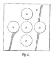
- the secondary 12 consists of five flat 19 mm (0.75 inch) thick ferritic stainless steel flat circular plate elements 36 which are 127 mm (5 inches) in diameter.
- the plate elements 36 are mounted on the underside of the chassis 32 in a cross-configuration (see Figure 4).
- the flat surfaces of the plate elements 36 face the primary 10.
- the air gap i.e. the distance between the flat faces of the secondary and the top of the primary, is 9.5 mm (0.37 inch).
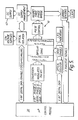
- All the modules or sections 18 are controlled by a central controller computer 38 (see Figure 6) which actuates a drive circuit 40 associated with a corresponding module 18.
- the drive circuit 40 energises the windings of the primary 10, to create the necessary travelling or stationary magnetic field to move or detain the secondary 12 mounted on the trolley 14.
- the drive circuit 40 is a three-phase pulse width modulated (PWM) inverter based on a power metal oxide silicon field effect transistor (MOSFET) three-phase bridge circuit having arms A, B and C corresponding to the three-phases (see Figure 7).
- the arms of the bridge of MOSFETS 42 are each driven by a digital transformer-isolated system from a d.c. supply 43 (see Figure 5).
- Feedback signals, relating to the position of the secondary with respect to the primary, are provided by Hall-effect transducers 44, which are placed strategically along the length of the primary 10.
- Each Hall-effect transducer device 44 is located centrally in a corresponding slot 20 above the associated winding therein but recessed slightly within the slot 20 to provide mechanical protection (see Figure 2).
- the Hall-effect device 44 will generate a change in output due to the distortion of the magnetic field created by the windings as the secondary 12 passes over it. This change in signal is fed to the controller computer 38 via a data acquisition module which converts the signals into a digital form.
- a pair of Hall-effect devices 44 are each mounted in corresponding slots 20 which are spaced apart by a distance corresponding to the overall length of the secondary 12 mounted on the trolley 14.
- the Hall-effect devices 44 are placed along the length of the primary 10 spaced from one another by the length of the secondary 12.
- a travelling magnetic wave of alternating north and south poles is set up between the slots 20 of the primary 10 by creating an eight-bit resolution digitised sinusoidal excitation current in the windings.
- the trolley 14 comprising the magnetic secondary 12 is caused to move along the duct at a speed related to the speed of movement of the travelling magnetic field substantially unaffected by the duct.
- the controller 38 can be operated to maintain a fixed or standing magnetic wave configuration and thus hold the secondary and the trolley 14 in a specific position.
- Each module or section 18 of primary 10 is separately driven by a dedicated drive circuit 40 under the command of the controller computer 38. By this, it is possible to control the movement of more than one trolley 14 on the same linear motor primary.
- the controller computer 38 is programmed to create a series of travelling magnetic waves. Each one of the waves carries with it a trolley 14. Between each moving trolley 14 is a dead region of unexcited windings of at least one module's length to create a suitable buffer zone to avoid the risk of collision between trolleys.
- the controller computer 38 counts the digitised steps in the increase and decrease in excitation current as the travelling wave moves through one of the modules 18 under the actuation of the associated drive circuit 40. In this way, the controller 38 is able to effect a smoother hand-over between modules 18 as the travelling magnetic wave passes along the length of the primary 10. This is because there is no ambiguity in the excitation of windings at the end of a module 18 which might otherwise occur if the windings in an adjacent module 18 were indpendently energised without reference to the excitation of the previous module.
- the count of the digitised steps of the energising current could also be used to derive information related to the position of the trolley 14 it is possible for the trolley to experience an amount of lag within the influence of the magnetic field. To a large extent this will be due to the weight of the material carried on the trolley.
- the Hall-effect transducers 44 the precise location of the trolley 14 can be monitored by measuring the increase in magnetic field without having to breach the duct.
- Table I summarises the dimensions and design data of the first embodiment of the invention.
- the solid core 16 is replaced by a laterally laminated alloy steel core.
- the laminations extend for the length of each module 18 and are held together by a series of lateral tie bolts in the bed of the core.
- Each slot defined by the laminated core is lined with a polyethylene lining sleeve which protects the windings from damage.
- the trolley is replaced by a static dry bearing surface of polytetrafluoroethylene (ptfe) which is fixed to the bottom surface 28 of the duct.
- ptfe polytetrafluoroethylene
- the article to be transported will have to include a suitable amount of ferritic material in order for it to be influenced by the travelling magnetic field.
- this aspect of the invention is particularly applicable to the food processing and canning industry in which experience has shown that it is prejudicial to sales of canned foodstuffs if the can appears dented or otherwise damaged whether or not the seal of the can is broken.
- the cans do not have to be isolated from the environment and the enclosed duct may be replaced by an open channel.
- the computer controller 38 is again programmed to create a series of travelling magnetic waves.
- Each one of the waves carries a plurality of cans sliding along the dry bearing surface.
- further primaries can be employed to create travelling magnetic waves which run parallel to the first. In this way a plurality of, for example, cans can be transported in a laterally spaced relationship, with respect to the original primary, by the travelling magnetic waves.
- the cans moved by the travelling magnetic wave are separated by one half of a wavelength such that a space exists between them. In this way the cans are transported without colliding.
- the ptfe bearing surface must be replaced when it is worn. To make it easier to do this it is possible to use a pair of ptfe rails received in grooves in the floor of the duct or channel. The rails can simply be stripped from the grooves and replaced with fresh ones as required.
- the secondary elements are hexagonal plates which are each mounted on the trolley 14 with two sides parallel to the longitudinal axis of the primary 10.
- the plates are dimensioned such that the central leading tip, with respect to the direction of movement of the secondary, is directly above the edge of a slot 20 as the laterally disposed tips are leaving the area directly above another of the slots 20.
- each of four interconnecting primary sections 50 is constructed around a central tie bar 52.
- the general principle of construction is illustrated with reference to a three-phase linear reluctance motor primary having portions intersecting at right angles, but clearly the invention is equally applicable to joined straight sections of primary, T-junctions and the like.
- the tie bars 52 are secured to a central cube 54 of magnetic steel and extend outwardly therefrom in a common plane.
- a plurality of insulated copper conducting disc-like coils 56 each of 100 turns, which constitute the excitation windings.
- Apertured plates 58 of magnetic steel are received on the tie bar 52, each interposed between adjacent coils 56.
- the plates 58 are acting as teeth which define slots in which the coils 56 are located.
- the end of each length of portion of primary 50 is completed by a nut (not shown) which is threadedly received on the tie bar 52 to hold the series of coils 56 and plates 58 in position.
- a secondary constructed on a trolley similarly to that described in relation to the first embodiment, can be used to transport the goods.
- the dimensions of the portions 50 of the second embodiment dictate that the dimensions of the secondary will be modified accordingly.
- a non-magnetic duct on which the trolley travels is mounted above the primary, as before.
- a controller computer is used to excite sections of windings to move more than one trolley at a time and to create the necessary supplementary excitation at a junction to change the direction of movement of the trolley.
- the inventors have also developed a further advantageous configuration of linear reluctance motor which is particularly applicable to the transport of goods in which at least a part of the goods constitute the ferritic secondary element, such as the cans previously described.
- the arrangement of the primary and secondary is inverted so that the active surface of the primary element is on its underside and the secondary is located beneath the primary element.
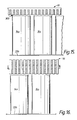
- FIG. 11 and 12 A first embodiment of this is shown in Figures 11 and 12 in relation to the diamond lap wound primary illustrated in Figure 1.
- the primary 10 is inverted and a non-magnetic barrier 28a is located beneath the active surface.
- the secondary consists of a plurality of at least partially ferritic payloads, such as cans 14a, travelling in rows abreast.
- the travelling magnetic field of the primary 10 creates an attractive force which is exerted on each secondary payload 14a.
- the force is greater than the force of gravity exerted on each payload 14a and each is thus attracted to the non-magnetic barrier 28a separating the primary and secondary.
- the travelling magnetic field also exerts the motive force on each payload tending to cause them to move along the barrier 28a beneath the primary 10.
- the windings of the motor are energised both to move the payload and to attract it to the barrier. Because the upward force exerted by the primary on the secondary is greater than the downward force of gravity only by sufficient to maintain the secondary in contact with the barriers the net force between barrier and secondary is significantly smaller than either force. Consequently, the enhanced friction due to the force of the contact between the payload and barrier is controllable so that it can be substantially reduced. Becuase of this a dry bearing surface between the barrier and payload, as previously described, is not necessary.
- FIG. 13 and 14 Another embodiment of the inverted configuration is illustrated in Figures 13 and 14 in which the ring-core construction of the primary 50 of Figure 8 is used.
- the principle of operation is substantially the same as that in the embodiment of Figure 11.
- the travelling magnetic field of the primary creates an upward force on the secondary as well as the propelling force.
- this upward force is less than that exerted by gravity on the payload and the payload remains in contact with the support.
- the attracting force exerted by the primary on the secondary is only slightly less than the force of gravity, the frictional force resisting motion of the secondary is much reduced. If the attractive force is chosen correctly to be sufficiently close to the force gravity a dry bearing surface may be unnecessary for loads that would otherwise require it.
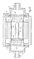
- a third embodiment of the invention is a control valve incorporated in a rotary reluctance motor.
- a motor casing 60 supports a stator 62 comprising a stator core 64 and three phase windings 66.
- a metal non-magnetic sleeve 68 is fitted within the internal diameter of the stator winding 66.
- a rotor 70 of ferritic stainless steel is rotatable within the non-magnetic sleeve 68.
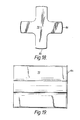
- the rotor 70 has a lateral cross-section in the form of a cross (see Figure 18).
- the arms 69 of the cross can be rotated to coincide with ports 71 in an end plate 72a.
- the end plate 72a is received within one end of the casing 60 to selectively engage the adjacent end of the sleeve 68 by means of an annular shoulder 74 which mates with an o-ring seal 76 located on the internal surface of the sleeve 68.
- a similar end plate 72b is received in the opposite end of the casing 60 and similarly engages an o-ring seal 76 in the sleeve 68.
- Each adaptor 78 is mounted on each end of the casing 60.
- Each adaptor 78 comprises an adaptor pipe 82 which opens into a chamber 83 adjacent a corresponding end plate 72 a or b.
- Each of the end plates 72a and b is clamped to the casing 60 by means of bolts (not shown) which extend through a flange 77 on the end-adaptor 78 of the casing 60, through a flange on the end plate 72 and into threaded holes in the casing 60.
- the rotor 70 has a dry bearing surface 84 of polytetrafluorothylene (ptfe) on an end face and ptfe dry bearing shoes 86 let into the ends of the radially outwardly facing surface of each arm 69, which bear against the internal surface of the sleeve 68.
- a ptfe dry bearing pad 73 is let into one face of the end plate 72a which has ports 71 through which fluid is delivered to the valve. The pad 73 is in sealing contact with the surface 84 on the end face of the rotor 70.
- the adaptor pipes 82 are connected into a fluid path to be controlled by the valve.
- the fluid to be controlled flows through ports 71 in one end of the casing 60, into the interior of the sleeve 68 and out through the ports 71 in the end plate 72b.
- the rotor 70 When the winding 66 of the three phase stator 62 are energised the rotor 70 will rotate within the sleeve 68 and also urge the dry bearing surfaces 84 axially with respect to the axis of the motor into sealing contact with the pad 73 of the adjacent end plate 72. Thus, as the rotor 70 rotates and the arms 69 register with the ports 71 in the end plate 72, the flow path therethrough is sealed off. A shift in the phase of the excitation of the winding 66 will rotate the rotor 70 out of sealing registration with the ports 71 and flow through the valve can be resumed. During relative movement between the rotor 70 and stator 62 the dry bearing plates 86 bear on the internal surface of the sleeve 68 and maintain the spaced relationship between the two.
- the motor casing 60 and three phase winding 66 are taken from a conventional induction motor, specifically one manufactured by the General Electric Company, model D90L, 1.5kw.
- valve assembly the only moving part of the valve assembly is the rotor of the motor which also constitutes the valve member.
- the pipework to which the valve is connected is sealed and no breach of the pipe wall is required to effect the control of the valve member.
- the actuator could execute a linear movement.
- a linear reluctance motor primary is used.
- the primary is energised to move a magnetisable gate which is the equivalent of the rotor 70.
- a non-magnetisable barrier which may completely define the fluid conduit through which the fluid whose flow is to be controlled passes.
- the primary is thus energisable to move the gate to permit or limit fluid flow through the conduit.
- the limited flow can constitute a fraction of the total flow or a total blockage.
- the barrier is constituted by a first pipe which is disposed within a second pipe of larger bore.
- the primary element is located outside at least the first pipe and actuates a secondary within the first pipe, which secondary is in the form of a toroid or disc located coaxially with respect to the first pipe.
- the secondary is actuated to move along the axis into and out of registry with a port in the wall of the pipe to control the flow from one pipe to the other.
- the shapes of the secondary and the ports can be designed to provide valve opening characteristics for a given amount of travel in accordance with a particular application, as will be apparent to the person skilled in the art.
Landscapes
- Engineering & Computer Science (AREA)
- Physics & Mathematics (AREA)
- Chemical & Material Sciences (AREA)
- Combustion & Propulsion (AREA)
- Electromagnetism (AREA)
- Power Engineering (AREA)
- Linear Motors (AREA)
- Control Of Linear Motors (AREA)
- Control Of Vehicles With Linear Motors And Vehicles That Are Magnetically Levitated (AREA)
- Non-Mechanical Conveyors (AREA)
Applications Claiming Priority (2)
| Application Number | Priority Date | Filing Date | Title |
|---|---|---|---|
| GB888804991A GB8804991D0 (en) | 1988-03-02 | 1988-03-02 | Improvements in electric motors |
| GB8804991 | 1988-03-02 |
Publications (1)
| Publication Number | Publication Date |
|---|---|
| EP0331463A1 true EP0331463A1 (de) | 1989-09-06 |
Family
ID=10632724
Family Applications (1)
| Application Number | Title | Priority Date | Filing Date |
|---|---|---|---|
| EP89302041A Withdrawn EP0331463A1 (de) | 1988-03-02 | 1989-03-01 | Elektrische Maschinen |
Country Status (3)
| Country | Link |
|---|---|
| EP (1) | EP0331463A1 (de) |
| JP (1) | JPH01268449A (de) |
| GB (1) | GB8804991D0 (de) |
Cited By (5)
| Publication number | Priority date | Publication date | Assignee | Title |
|---|---|---|---|---|
| US6355993B1 (en) | 1998-04-10 | 2002-03-12 | Nikon Corporation | Linear motor having polygonal shaped coil units |
| WO2006077511A1 (en) * | 2005-01-18 | 2006-07-27 | Koninklijke Philips Electronics N.V. | Coil assembly for use with an electric motor |
| CN103746535A (zh) * | 2014-01-20 | 2014-04-23 | 长沙一派数控机床有限公司 | 一种流体支撑直线电机 |
| CN112953159A (zh) * | 2021-04-26 | 2021-06-11 | 合肥工业大学 | 一种高推力密度的双边型永磁辅助直线同步磁阻电机 |
| CN113726262A (zh) * | 2021-09-02 | 2021-11-30 | 实时侠智能控制技术有限公司 | 一种磁输送线驱动系统、磁输送线和磁输送线驱动方法 |
Citations (10)
| Publication number | Priority date | Publication date | Assignee | Title |
|---|---|---|---|---|
| FR788423A (fr) * | 1934-07-13 | 1935-10-10 | Dispositif pour le transport de lettres ou autres objets analogues | |
| FR1249223A (fr) * | 1957-10-07 | 1960-12-30 | Propulseur-pompe électro-magnétique | |
| US3167168A (en) * | 1963-08-15 | 1965-01-26 | Chester P Park | Electromagnetic conveyor |
| US3708251A (en) * | 1968-07-01 | 1973-01-02 | North American Rockwell | Gearless drive method and means |
| FR2277016A1 (fr) * | 1974-07-04 | 1976-01-30 | Peugeot & Renault | Dispositif perfectionne pour le transport de pieces metalliques |
| FR2369716A1 (fr) * | 1976-10-29 | 1978-05-26 | Auxilec | Structure de la partie fixe et de la partie mobile d'un systeme a reluctance variable |
| FR2386181A1 (fr) * | 1977-03-31 | 1978-10-27 | Higelin Morand | Generatrices et moteurs electriques mono et polyphases, lineaires et circulaires a dents de transfert et de modulation des flux magnetiques |
| DE2903817A1 (de) * | 1979-02-01 | 1980-08-07 | Siegfried Dr Ing Kofink | Elektromagnetische kolbenpumpe fuer fluessige und gasfoermige medien |
| DE3037648A1 (de) * | 1979-10-17 | 1981-04-30 | Jenoptik Jena Gmbh, Ddr 6900 Jena | Zweikoordinatenschrittmotor |
| EP0207353A1 (de) * | 1985-06-25 | 1987-01-07 | Kabushiki Kaisha Yaskawa Denki Seisakusho | Oberflächen-Impulsmotor |
-
1988
- 1988-03-02 GB GB888804991A patent/GB8804991D0/en active Pending
-
1989
- 1989-03-01 EP EP89302041A patent/EP0331463A1/de not_active Withdrawn
- 1989-03-02 JP JP1050970A patent/JPH01268449A/ja active Pending
Patent Citations (10)
| Publication number | Priority date | Publication date | Assignee | Title |
|---|---|---|---|---|
| FR788423A (fr) * | 1934-07-13 | 1935-10-10 | Dispositif pour le transport de lettres ou autres objets analogues | |
| FR1249223A (fr) * | 1957-10-07 | 1960-12-30 | Propulseur-pompe électro-magnétique | |
| US3167168A (en) * | 1963-08-15 | 1965-01-26 | Chester P Park | Electromagnetic conveyor |
| US3708251A (en) * | 1968-07-01 | 1973-01-02 | North American Rockwell | Gearless drive method and means |
| FR2277016A1 (fr) * | 1974-07-04 | 1976-01-30 | Peugeot & Renault | Dispositif perfectionne pour le transport de pieces metalliques |
| FR2369716A1 (fr) * | 1976-10-29 | 1978-05-26 | Auxilec | Structure de la partie fixe et de la partie mobile d'un systeme a reluctance variable |
| FR2386181A1 (fr) * | 1977-03-31 | 1978-10-27 | Higelin Morand | Generatrices et moteurs electriques mono et polyphases, lineaires et circulaires a dents de transfert et de modulation des flux magnetiques |
| DE2903817A1 (de) * | 1979-02-01 | 1980-08-07 | Siegfried Dr Ing Kofink | Elektromagnetische kolbenpumpe fuer fluessige und gasfoermige medien |
| DE3037648A1 (de) * | 1979-10-17 | 1981-04-30 | Jenoptik Jena Gmbh, Ddr 6900 Jena | Zweikoordinatenschrittmotor |
| EP0207353A1 (de) * | 1985-06-25 | 1987-01-07 | Kabushiki Kaisha Yaskawa Denki Seisakusho | Oberflächen-Impulsmotor |
Cited By (9)
| Publication number | Priority date | Publication date | Assignee | Title |
|---|---|---|---|---|
| US6355993B1 (en) | 1998-04-10 | 2002-03-12 | Nikon Corporation | Linear motor having polygonal shaped coil units |
| US6373153B1 (en) | 1998-04-10 | 2002-04-16 | Nikon Corporation | Stage device, and exposure apparatus with linear motor having polygonal shaped coil units |
| WO2006077511A1 (en) * | 2005-01-18 | 2006-07-27 | Koninklijke Philips Electronics N.V. | Coil assembly for use with an electric motor |
| CN103746535A (zh) * | 2014-01-20 | 2014-04-23 | 长沙一派数控机床有限公司 | 一种流体支撑直线电机 |
| CN103746535B (zh) * | 2014-01-20 | 2016-01-27 | 长沙一派数控股份有限公司 | 一种流体支撑直线电机 |
| CN112953159A (zh) * | 2021-04-26 | 2021-06-11 | 合肥工业大学 | 一种高推力密度的双边型永磁辅助直线同步磁阻电机 |
| CN112953159B (zh) * | 2021-04-26 | 2022-07-12 | 合肥工业大学 | 一种高推力密度的双边型永磁辅助直线同步磁阻电机 |
| CN113726262A (zh) * | 2021-09-02 | 2021-11-30 | 实时侠智能控制技术有限公司 | 一种磁输送线驱动系统、磁输送线和磁输送线驱动方法 |
| CN113726262B (zh) * | 2021-09-02 | 2024-04-19 | 上海捷勃特机器人有限公司 | 一种磁输送线驱动系统、磁输送线和磁输送线驱动方法 |
Also Published As
| Publication number | Publication date |
|---|---|
| GB8804991D0 (en) | 1988-03-30 |
| JPH01268449A (ja) | 1989-10-26 |
Similar Documents
| Publication | Publication Date | Title |
|---|---|---|
| US12341043B2 (en) | Modular material handling robot platform | |
| US6876107B2 (en) | Controlled motion system | |
| US10843880B2 (en) | Linear-motor conveyor system | |
| CN102387973B (zh) | 改进的由短块线性同步电机和换向机构驱动的运输系统 | |
| TWI272665B (en) | Universal modular wafer transport system | |
| US6770988B2 (en) | Linear electromagnetic machine | |
| US8616134B2 (en) | Transport system powered by short block linear synchronous motors | |
| US4766993A (en) | Conveying apparatus | |
| WO2019238416A1 (de) | Beförderungsvorrichtung zum befördern mindestens eines wafers | |
| US12395057B2 (en) | Stator modules and robotic systems | |
| EP0331463A1 (de) | Elektrische Maschinen | |
| US20210370777A1 (en) | System and Method for Collision Prevention in a Linear Motion System | |
| JPH0687603B2 (ja) | 浮上式搬送装置 | |
| US4216397A (en) | Linear induction motor | |
| US20190305661A1 (en) | Curvilinear motor | |
| DE3402143C2 (de) | Verfahren und Vorrichtung zum berührungsfreien Fördern von Gegenständen | |
| CN206232123U (zh) | 磁性直线导轨模组及磁性直线导轨装置 | |
| CN114228751A (zh) | 一种采用直线电机驱动的物流传输系统 | |
| JPH0741992B2 (ja) | 磁気浮上搬送装置 | |
| JPH04269148A (ja) | 移動磁界による電磁誘導作用を利用した切粉(キリコ)除去装 置 | |
| JPH03112301A (ja) | リニア式カプセル型走行装置の管路分岐装置 | |
| JPS62166706A (ja) | 磁気浮上式のリニアモ−タ利用の搬送設備 | |
| WO2026025198A2 (en) | Stator device for a displacement system | |
| JPH0676235U (ja) | 磁気浮上式搬送装置 | |
| JPH06156731A (ja) | 搬送装置 |
Legal Events
| Date | Code | Title | Description |
|---|---|---|---|
| PUAI | Public reference made under article 153(3) epc to a published international application that has entered the european phase |
Free format text: ORIGINAL CODE: 0009012 |
|
| AK | Designated contracting states |
Kind code of ref document: A1 Designated state(s): AT BE CH DE ES FR GB GR IT LI LU NL SE |
|
| 17P | Request for examination filed |
Effective date: 19900226 |
|
| STAA | Information on the status of an ep patent application or granted ep patent |
Free format text: STATUS: THE APPLICATION IS DEEMED TO BE WITHDRAWN |
|
| 18D | Application deemed to be withdrawn |
Effective date: 19911015 |