EP0331517A2 - Procédé de fabrication d'un aimant permanent à base de terre rare - Google Patents
Procédé de fabrication d'un aimant permanent à base de terre rare Download PDFInfo
- Publication number
- EP0331517A2 EP0331517A2 EP89302154A EP89302154A EP0331517A2 EP 0331517 A2 EP0331517 A2 EP 0331517A2 EP 89302154 A EP89302154 A EP 89302154A EP 89302154 A EP89302154 A EP 89302154A EP 0331517 A2 EP0331517 A2 EP 0331517A2
- Authority
- EP
- European Patent Office
- Prior art keywords
- magnet
- heat treatment
- solid solution
- solution heat
- ingot
- Prior art date
- Legal status (The legal status is an assumption and is not a legal conclusion. Google has not performed a legal analysis and makes no representation as to the accuracy of the status listed.)
- Granted
Links
Images
Classifications
-
- H—ELECTRICITY
- H01—ELECTRIC ELEMENTS
- H01F—MAGNETS; INDUCTANCES; TRANSFORMERS; SELECTION OF MATERIALS FOR THEIR MAGNETIC PROPERTIES
- H01F1/00—Magnets or magnetic bodies characterised by the magnetic materials therefor; Selection of materials for their magnetic properties
- H01F1/01—Magnets or magnetic bodies characterised by the magnetic materials therefor; Selection of materials for their magnetic properties of inorganic materials
- H01F1/03—Magnets or magnetic bodies characterised by the magnetic materials therefor; Selection of materials for their magnetic properties of inorganic materials characterised by their coercivity
- H01F1/032—Magnets or magnetic bodies characterised by the magnetic materials therefor; Selection of materials for their magnetic properties of inorganic materials characterised by their coercivity of hard-magnetic materials
- H01F1/04—Magnets or magnetic bodies characterised by the magnetic materials therefor; Selection of materials for their magnetic properties of inorganic materials characterised by their coercivity of hard-magnetic materials metals or alloys
- H01F1/047—Alloys characterised by their composition
- H01F1/053—Alloys characterised by their composition containing rare earth metals
- H01F1/055—Alloys characterised by their composition containing rare earth metals and magnetic transition metals, e.g. SmCo5
- H01F1/0555—Alloys characterised by their composition containing rare earth metals and magnetic transition metals, e.g. SmCo5 pressed, sintered or bonded together
- H01F1/0557—Alloys characterised by their composition containing rare earth metals and magnetic transition metals, e.g. SmCo5 pressed, sintered or bonded together sintered
-
- H—ELECTRICITY
- H01—ELECTRIC ELEMENTS
- H01F—MAGNETS; INDUCTANCES; TRANSFORMERS; SELECTION OF MATERIALS FOR THEIR MAGNETIC PROPERTIES
- H01F1/00—Magnets or magnetic bodies characterised by the magnetic materials therefor; Selection of materials for their magnetic properties
- H01F1/01—Magnets or magnetic bodies characterised by the magnetic materials therefor; Selection of materials for their magnetic properties of inorganic materials
- H01F1/03—Magnets or magnetic bodies characterised by the magnetic materials therefor; Selection of materials for their magnetic properties of inorganic materials characterised by their coercivity
- H01F1/032—Magnets or magnetic bodies characterised by the magnetic materials therefor; Selection of materials for their magnetic properties of inorganic materials characterised by their coercivity of hard-magnetic materials
- H01F1/04—Magnets or magnetic bodies characterised by the magnetic materials therefor; Selection of materials for their magnetic properties of inorganic materials characterised by their coercivity of hard-magnetic materials metals or alloys
- H01F1/047—Alloys characterised by their composition
- H01F1/053—Alloys characterised by their composition containing rare earth metals
- H01F1/055—Alloys characterised by their composition containing rare earth metals and magnetic transition metals, e.g. SmCo5
Definitions
- the present invention relates to a rare earth permanent magnet which is useful not only for various electric and electronic devices, but also for motors installed in automotive vehicles. More particularly it relates to a high-performance magnet of the type containing cerium as the rare earth element, with the typical ratio of Ce to other elements being 1 : 5.
- Ce-containing magnets and Sm-containing magnets which are basically composed of intermetallic compounds, CeCo5 and SmCo5, respectively, are widely employed. (These are conventionally called 1/5 magnets.)
- the use of the Sm-containing 1/5 magnets in the fields of electric devices and electronics has sharply increased, despite the fact that these magnets contain expensive samarium and cobalt, because the Sm-containing magnets are capable of exhibiting very high magnetic characteristics.
- the maximum energy products (BH) max of some Sm-containing 1/5 magnets are about 20 MG ⁇ Oe, which is several times as high as those of conventional ferrite and Alnico magnets.
- a permanent magnet formed from SmCo5 and Sm2C o7 which has an energy product as high as 15 MG ⁇ Oe and up to 20 MG ⁇ Oe is disclosed in U.S. Pat. No.4,075,042.
- Sm-containing magnets it is known that high magnetic characteristics are maintained even when the Fe content exceeds 0.2 or approaches 0.3 (ref. J. Appl. Phys. 52(3)2517, 1981). These Sm-containing magnets wherein the Fe content is from 0.2 to 0.3 are conventionally called "2/17 magnets" because the ratio of Sm content to the others is roughly 2 : 17.
- An object of the present invention is to provide Ce-containing magnets which has high Fe contents and exhibits the desired level of magnetic properties. The Sm-containing 2/17 magnets do not suggest how to do this, since the solid solubility of Fe in Sm-containing 2/17 magnets is quite different from that in Ce-containing 1/5 magnets.
- Magnets which exhibit a maximum energy product of 10 MG ⁇ Oe or higher include NdFeB magnets and SmCo plastic magnets. Although the former contain materials which give rise to high magnetic properties, the stability of their magnetic properties with respect to temperature changes is poor. Also, the existence of neodymium renders the magnet so vulnerable to oxidation (rusting) that it must be coated, and consequently the overall cost becomes as high as that of Sm-containing 2/17 magnets.
- the SmCo plastic magnet is favored because it can be formed in arbitrary shapes and it needs no finishing treatments such as coating. However, since a magnetic powder containing 90 wt% or more of samarium must be employed, the material cost becomes very high.
- a rare earth permanent magnet with a decreased Co content and which possesses good magnetic properties whose composition is represented by the formula: Ce(Co 1-x-y-a Fe x Cu y M a ) z in which a, x, y, and z are numbers falling in the following ranges: 0.005 ⁇ a ⁇ 0.10; 0.2 ⁇ x ⁇ 0.4; 0.10 ⁇ y ⁇ 0.30; 4.8 ⁇ z ⁇ 6.0; and M designates one or more elements selected from zirconium, titanium, nickel, and manganese.
- x, y, and z are such that: 0.010 ⁇ a ⁇ 0.060; 0.20 ⁇ x ⁇ 0.30; 0.15 ⁇ y ⁇ 0.25; and 4.8 ⁇ z ⁇ 5.5.
- the invention also provides a method for manufacturing the rare earth permanent magnet of the above compositions which method comprises steps of: (i) applying a first solid solution heat treatment to an alloy ingot having the above composition at temperatures of from 900 to 1100°C for a period from 10 minutes to 100 hours; (ii) pulverizing the alloy ingot; (iii) obtaining a magnet body from this pulverized alloy by the powder metallurgy method; (iv) sintering the magnet; (v) applying a second solid solution heat treatment to the sintered magnet at temperatures of from 900 to 1100°C for a period from 10 minutes to 100 hours; and (vi) applying an aging heat treatment to the sintered magnet.
- the first and second solid solution heat treatments described above are conducted at temperatures of 900 to 1000°C for a period from one hour to 30 hours.
- the permanent magnet according to the present invention can be said to be a very iron-rich magnet. If the fraction x is smaller than 0.2, the magnetic properties of the magnet of the invention degrade to the level of the conventional magnets so that the economical merit gained through reduction of the Co content is mostly cancelled. If the fraction x is greater than 0.4, the coercive force (iHc) decreases and the squareness of the magnetic hysteresis loop is largely lost, i.e., the value given by 4Br ⁇ 2(BH) max becomes far smaller than unity, Br being the residual magnetization, such that the magnet cannot be put to practical use.
- iHc coercive force
- the conventional Ce-containing magnets having comparatively high Fe contents do not exhibit desirous magnetic properties because the Fe dendrite phase existing in the ingot does not orient when the magnet powder is pressed in a magnetic field and the Fe dendrite phase reacts with its surrounding fine powder during sintering, thereby affecting the orientation degree of the sintered magnet.
- the Cu content is restricted such that 0.10 ⁇ y ⁇ 0.30 since if y ⁇ 0.1, the coercive force (iHc) becomes too small and if y>0.30, the saturation magnetization (4 ⁇ Ms) becomes too low.
- one or more elements selected from the group of Zr, Ti, Ni, Mn is/are contained, which have the effect of improving the squareness of the magnetic hysteresis loop, i.e., causing the value 4Br ⁇ 2(BH) max to approach unity.
- These additives (M) are not capable of improving the coercive force (iHc) of the Ce-containing magnets, unlike the case of the Sm-containing magnets.
- the amount of the additive(s) M is such that a ⁇ 0.005
- the squareness of the magnetic hysteresis loop is not appreciably improved, and if a>0.10, the saturation magnetization is significantly lowered.
- the ratio of the Ce content to the non-Ce content when the ratio is such that z ⁇ 4.8 or 6.0 ⁇ z, the coercive force and the squareness of the magnetic hysteresis loop are both significantly affected adversely.
- the solid solution heat treatment of the invention should be applied twice, first to the ingot form and then to the sintered form.
- the reason for applying the solid solution heat treatment to the ingot form is to cause the Fe dendrite phase to disappear from the ingot and obtain a uniform 1-5 phase throughout the ingot.
- the reason for restricting the temperature to effect the solid solution formation to the range of 900 to 1100°C is that if the temperature is lower than 900 °C, the Fe dendrite phase does not disappear, and if the temperature is higher than 1100 °C, a phase separates from the 1-5 phase having a melting point lower than that of the 1-5 phase, whereby the magnetic properties are degraded.
- the second solid solution heat treatment applied after sintering since the sintering temperature is 10 to 100 °C higher than the temperature for effecting solid solution formation, a phase of a relatively low melting point separates in the sintered alloy if the Fe content of the alloy is not sufficiently low. Consequently, the formation of the uniform 1-5 phase is not achieved like on the occasion of applying the first solid solution heat treatment to the ingot. Therefore, it is necessary to adopt the same temperature range and the same time range in conducting the second solid solution heat treatment, as the first solid solution heat treatment. If, and only if, these conditions are observed, can one achieve uniform 1-5 phase in the alloy and obtain the desired magnetic properties.
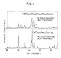
- Fig. 1 shows the X-ray diffractions of an alloy ingot of the inventive composition represented by Ce(Co 0.515 Fe 0.25 Cu 0.175 Ni 0.05 Zr 0.01 ) 5.2 , and of an alloy ingot of the composition represented by Ce(Co 0.72 Fe 0.14 Cu 0.14 ) 5.0 , which belongs to the prior art.
- the line width* of the peaks characteristic of the CaCu5 structure exhibited by the alloy of the present invention is larger than those exhibited by the alloy of the prior art.
- the X-ray diffraction of the alloy of the present invention includes peaks that are foreign to the CaCu5 structure as indicated by the arrows in Fig. 1.
- the line width of a peak in an X-ray diffraction chart is the width of the peak at the middle height of the peak.
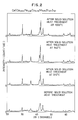
- the upper X-ray diffraction pattern in Fig. 1 is reproduced at the bottom of Fig. 2, for comparison with the X-ray diffractions of the ingot of the same composition of the present invention after the solid solution heat treatment at temperatures at 910 °C, 940 °C, and 1000 °C, respectively. It is seen that as a result of the solid solution heat treatment at these temperatures, the ingot of the invention became purer in CaCu5 structure, which provides the easily magnetizable phase. Of these temperatures, 940 °C is the optimum temperature for this solid solution heat treatment, because the X-ray diffraction obtained after the heat treatment at 940 °C is the one most akin to the diffraction pattern attributable to the CaCu5 structure.
- a magnet in the form of an ingot having the composition of Ce(Co 0.53 Fe 0.25 Cu 0.18 Ni 0.03 Ti 0.01 ) 5.5 was prepared.
- the contents of Co and Fe were 37.0 wt% and 16.6 wt%, respectively. See No. 1 (a) in Table 1.
- the additives were Ni and Ti.
- This ingot was melted in an argon atmosphere of 1 atm by induction heating and a magnetic ingot was obtained.
- this ingot was placed in a sintering furnace and was subjected to solid solution heat treatment in an argon atmosphere of 200 Torr at 920 °C which lasted for 20 hours. As a result, the Fe dendrite phase disappeared and a uniform 1-5 phase was obtained.
- this ingot was pulverized and reformed into a magnet by means of the powder metallurgy method using the following procedures.
- the ingot was roughly pulverized by a crusher (a jaw crusher and a Brown mill), then the crushed fragments were finely pulverized to a mean particle diameter of 3 ⁇ m by a nitrogen gas jet mill.
- This fine powder was oriented in a static magnet field of 10 kOe, and pressed under a pressure of 2 t/cm2 .
- the compact was sintered in the sintering furnace for one hour at a temperature of 1020 °C in an argon atmosphere of 200 Torr.
- the sintered body was subjected to a second solid solution heat treatment at 990 °C, which lasted two hours. This caused the phase of lower melting point, which separated during the sintering operation, to disappear and become an integral part of the uniform 1-5 phase again.
- the magnet body was subjected to an aging heat treatment at 500 °C in an argon atmosphere of 1 atm, and a permanent magnet having the properties as shown in No. 1 (a) in Table 1 was obtained.
- a magnet of the same composition was made in the same manner as the magnet of No.1 (a) except that the first and second solid solution heat treatments were not applied.
- the magnetic properties of the resulting magnet are shown at No.1 (b) in Table 1.
- the No. 1 (b) magnet exhibits poorer magnetic properties in all of aspects shown in the Table 1, for the apparent reason that the uniform 1-5 phase failed to develop exclusively, and as a result, much of the squareness of the magnetic hysteresis loop was lost.
- a magnet in the form of an ingot having the composition of Ce(Co 0.58 Fe 0.25 Cu 0.16 Zr 0.01 ) 5.2 was prepared.
- the contents of Co and Fe were 39.7 wt% and 16.2 wt%, respectively. See No. 2 (a) in Table 1.
- Zirconium was the only additive.
- This ingot was processed in the same manner as in Example 1 except that the ingot was subjected to the first solid solution heat treatment at 960°C for ten hours. As a result, a permanent magnet having the properties as shown in No. 2 (a) in Table 1 was obtained.
- a magnet of the same composition was made in the same manner as the magnet of No.2 (a) except that the first and second solid solution heat treatments were not applied.
- the magnetic properties of the resulting magnet are shown at No.2 (b) in Table 1.
- the No. 2 (b) magnet exhibits poorer magnetic properties in all aspects since the uniform 1-5 phase failed to develop exclusively, and consequently, the squareness of the magnetic hysteresis loop was much lost.
- a magnet in the form of an ingot having the composition of Ce(Co 0.515 Fe 0.25 Cu 0.175 Ni 0.05 Zr 0.01 ) 5.2 was prepared.
- the contents of Co and Fe were 35.2 wt% and 16.2 wt%, respectively. See No. 3 (a) in Table 1.
- the additives were nickel and zirconium.
- This ingot was processed in the same manner as in Example 1 except for the following details.
- the ingot was subjected to the first solid solution heat treatment at 960 °C for four hours.
- the compact was sintered for one hour at 1010 °C. After sintering, the solid solution heat treatment was conducted at 950 °C for three hours.
- the temperature for the aging heat treatment was controlled to 550 °C.
- a permanent magnet having the properties as shown in No. 3 (a) in Table 1 was obtained.
- a magnet of the same composition was made in the same manner as the magnet of No. 3 (a) except that the first solid solution heat treatment was not applied.
- the magnetic properties of the resulting magnet are shown at No. 3 (b) in Table 1.
- the No. 3 (b) magnet exhibits poorer magnetic properties in all aspects, although the squareness of the magnetic hysteresis loop was not as bad as No.1 (b) and No. 2 (b) magnets. It is therefore clear that the first solid solution heat treatment applied to the ingot is essential.
- a magnet in the form of an ingot having the composition of Ce(Co 0.44 Fe 0.30 Cu 0.20 Ni 0.05 Zr 0.01 ) 5.3 was prepared.
- the contents of Co and Fe were 30.3 wt% and 19.6 wt%, respectively. See No. 4 (a) in Table 1.
- the additives were nickel and zirconium.
- This ingot was processed in the same manner as in Example 1 except for the following details.
- the ingot was subjected to the first solid solution heat treatment at 980 °C for ten hours. After sintering, the second solid solution heat treatment was conducted at 930 °C for four hours.
- the temperature for the aging heat treatment was controlled to 550 °C.
- a permanent magnet having the properties as shown in No. 4 (a) in Table 1 was obtained.
- a magnet of the same composition was made in the same manner as the magnet of No. 4 (a) except that the second solid solution heat treatment was not applied.
- the magnetic properties of the resulting magnet are shown at No.4 (b) in Table 1.
- the No. 4 (b) magnet exhibits poorer magnetic properties in all aspects but the residual magnetization, or remanence, (Br).
- the squareness of the magnetic hysteresis loop was even worse than that of No.3 (b) and it is clear that the second solid solution heat treatment applied after the sintering is essential too.
- a magnet in the form of an ingot having the composition of Ce(Co 0.41 Fe 0.35 Cu 0.20 Mn 0.03 Zr 0.01 ) 5.5 was prepared.
- the contents of Co and Fe were 28.6 wt% and 23.1 wt%, respectively. See No. 5 in Table 1.
- the additives were manganese and zirconium.
- This ingot was processed in the same manner as in Example 1 except for the following details.
- the ingot was subjected to the first solid solution heat treatment at 990 °C for twenty hours.
- the compact was sintered for two hours at 1030°C. After sintering, the second solid solution heat treatment was conducted at 970 °C for ten hours.
- the temperature for the aging heat treatment was controlled to 600 °C.
- a permanent magnet having the properties as shown in No. 5 in Table 1 was obtained. It is noted that the iron content is as high as 23.1 wt%, and that the residual magnetization is quite high.
- a magnet in the form of an ingot having the composition of Ce(Co 0.45 Fe 0.30 Cu 0.25 ) 5.5 was prepared.
- the contents of Co and Fe were 31.3 wt% and 19.8 wt%, respectively. See No. 7 in Table 2. No additives were used, and therefore the composition is outside the scope of the invention.
- This ingot was melted in an argon atmosphere of 1 atm by induction heating and a magnetic ingot was obtained. Next, this ingot was placed in a sintering furnace and was subjected to solid solution heat treatment in an argon atmosphere of 200 Torr at 980 °C which lasted for 10 hours.
- this ingot was pulverized and reformed into a magnet by means of the powder metallurgy method using the following procedures.
- the ingot was roughly pulverized by a crusher (a jaw crusher and a Brown mill), then the crushed fragments were finely pulverized to a mean particle diameter of 3 ⁇ m by a nitrogen gas jet mill.
- This fine powder was oriented in a static magnet field, and pressed under a pressure of 2 t/cm2 .
- the compact was sintered in the sintering furnace for two hours at a temperature of 1030 °C in an argon atmosphere of 200 Torr. After the sintering the sintered body was subjected to a second solid solution heat treatment at 950 °C which lasted four hours. Thereafter, the magnet body was subjected to an aging heat treatment at 550 °C in an argon atmosphere of 1 atm, and a permanent magnet having the properties as shown in No. 7 in Table 2 was obtained.
- the magnet of this composition exhibits a low squareness of the magnetic hysteresis loop compared with Examples 1 through 5, and the magnetic properties are also low.
- a magnet in the form of an ingot having the composition of Ce(Co 0.31 Fe 0.45 Cu 0.20 Mn 0.03 Zr 0.01 ) 5.0 was prepared.
- the contents of Co and Fe were 21.1 wt% and 29.0 wt%, respectively. See No. 6 in Table 2.
- the additives used were Mn and Zr like Example 5, and the fraction x of Fe content is as high as 0.45 and thus the composition is outside the scope of the invention.
- This ingot was processed in the same manner as in Comparative Example 2 except that the first solid solution heat treatment was conducted at 980 °C for 30 hours.
- the compact obtained after the powder metallurgy was sintered at 1020 °C for two hours.
- the sintered body was subjected to a second solid solution heat treatment at 970 °C for twenty hours.
- the subsequent aging heat treatment was conducted at 620 °C, and a permanent magnet having the properties as shown in No. 6 in Table 2 was obtained.
Landscapes
- Chemical & Material Sciences (AREA)
- Crystallography & Structural Chemistry (AREA)
- Inorganic Chemistry (AREA)
- Engineering & Computer Science (AREA)
- Power Engineering (AREA)
- Hard Magnetic Materials (AREA)
Applications Claiming Priority (2)
| Application Number | Priority Date | Filing Date | Title |
|---|---|---|---|
| JP50799/88 | 1988-03-04 | ||
| JP63050799A JPH01225101A (ja) | 1988-03-04 | 1988-03-04 | 希土類永久磁石 |
Publications (3)
| Publication Number | Publication Date |
|---|---|
| EP0331517A2 true EP0331517A2 (fr) | 1989-09-06 |
| EP0331517A3 EP0331517A3 (en) | 1990-09-26 |
| EP0331517B1 EP0331517B1 (fr) | 1993-09-15 |
Family
ID=12868833
Family Applications (1)
| Application Number | Title | Priority Date | Filing Date |
|---|---|---|---|
| EP89302154A Expired - Lifetime EP0331517B1 (fr) | 1988-03-04 | 1989-03-03 | Procédé de fabrication d'un aimant permanent à base de terre rare |
Country Status (4)
| Country | Link |
|---|---|
| US (1) | US5057165A (fr) |
| EP (1) | EP0331517B1 (fr) |
| JP (1) | JPH01225101A (fr) |
| DE (1) | DE68909070T2 (fr) |
Cited By (2)
| Publication number | Priority date | Publication date | Assignee | Title |
|---|---|---|---|---|
| DE4015683A1 (de) * | 1990-05-16 | 1991-11-21 | Schramberg Magnetfab | Legierung fuer permanentmagnete sowie verfahren zum hestellen von permanentmagneten aus dieser legierung |
| CN112435846A (zh) * | 2020-10-28 | 2021-03-02 | 包头市沃野对外贸易有限责任公司 | 一种耐550度高温型钐钴永磁材料的制造方法 |
Families Citing this family (4)
| Publication number | Priority date | Publication date | Assignee | Title |
|---|---|---|---|---|
| FR2686730B1 (fr) * | 1992-01-23 | 1994-11-04 | Aimants Ugimag Sa | Methode de reglage de l'induction remanente d'un aimant fritte et produit ainsi obtenu. |
| CN1044940C (zh) * | 1992-08-13 | 1999-09-01 | Ybm麦格奈克斯公司 | 基于钕铁硼的生产永久磁铁的方法 |
| CN1297678C (zh) * | 2001-11-09 | 2007-01-31 | 株式会社三德 | 用于Sm-Co基磁体的合金,其生产方法,烧结磁体以及粘结磁体 |
| CN102436888A (zh) * | 2011-12-21 | 2012-05-02 | 钢铁研究总院 | 一种铈基1:5永磁材料及制备方法 |
Family Cites Families (8)
| Publication number | Priority date | Publication date | Assignee | Title |
|---|---|---|---|---|
| JPS5417284B2 (fr) * | 1974-04-10 | 1979-06-28 | ||
| CH603802A5 (fr) * | 1975-12-02 | 1978-08-31 | Bbc Brown Boveri & Cie | |
| JPS5496421A (en) * | 1978-01-17 | 1979-07-30 | Tdk Corp | Permanent magnet material |
| JPS5810454B2 (ja) * | 1980-02-07 | 1983-02-25 | 住友特殊金属株式会社 | 永久磁石合金 |
| JPS58125804A (ja) * | 1982-01-22 | 1983-07-27 | Sumitomo Special Metals Co Ltd | 永久磁石の原料粉末およびその製造方法 |
| JPS58153306A (ja) * | 1982-03-08 | 1983-09-12 | Seiko Instr & Electronics Ltd | 希土類磁石の製造方法 |
| JPS60121239A (ja) * | 1983-12-06 | 1985-06-28 | Hitachi Metals Ltd | 永久磁石合金の製造方法 |
| JPS6328844A (ja) * | 1986-07-23 | 1988-02-06 | Toshiba Corp | 永久磁石材料 |
-
1988
- 1988-03-04 JP JP63050799A patent/JPH01225101A/ja active Pending
-
1989
- 1989-03-03 DE DE89302154T patent/DE68909070T2/de not_active Expired - Fee Related
- 1989-03-03 EP EP89302154A patent/EP0331517B1/fr not_active Expired - Lifetime
-
1990
- 1990-07-27 US US07/558,788 patent/US5057165A/en not_active Expired - Fee Related
Cited By (2)
| Publication number | Priority date | Publication date | Assignee | Title |
|---|---|---|---|---|
| DE4015683A1 (de) * | 1990-05-16 | 1991-11-21 | Schramberg Magnetfab | Legierung fuer permanentmagnete sowie verfahren zum hestellen von permanentmagneten aus dieser legierung |
| CN112435846A (zh) * | 2020-10-28 | 2021-03-02 | 包头市沃野对外贸易有限责任公司 | 一种耐550度高温型钐钴永磁材料的制造方法 |
Also Published As
| Publication number | Publication date |
|---|---|
| DE68909070T2 (de) | 1994-01-20 |
| EP0331517B1 (fr) | 1993-09-15 |
| JPH01225101A (ja) | 1989-09-08 |
| DE68909070D1 (de) | 1993-10-21 |
| US5057165A (en) | 1991-10-15 |
| EP0331517A3 (en) | 1990-09-26 |
Similar Documents
| Publication | Publication Date | Title |
|---|---|---|
| US4601875A (en) | Process for producing magnetic materials | |
| EP0251871B1 (fr) | Aimant permanent à base de terre rare | |
| US5071493A (en) | Rare earth-iron-boron-based permanent magnet | |
| US4284440A (en) | Rare earth metal-cobalt permanent magnet alloy | |
| EP0258609B1 (fr) | Aimant permanent à bonne stabilité thermique | |
| US4971637A (en) | Rare earth permanent magnet | |
| US3947295A (en) | Hard magnetic material | |
| JPH07105289B2 (ja) | 希土類永久磁石の製造方法 | |
| US5230751A (en) | Permanent magnet with good thermal stability | |
| JP2720040B2 (ja) | 焼結永久磁石材料とその製造方法 | |
| EP0331517B1 (fr) | Procédé de fabrication d'un aimant permanent à base de terre rare | |
| Kuhrt | Processing of permanent magnet materials based on rare earth-transition metal intermetallics | |
| JPH10106875A (ja) | 希土類磁石の製造方法 | |
| JPH04268051A (ja) | 不可逆減磁の小さい熱安定性に優れたR−Fe−Co−B−C系永久磁石合金 | |
| JP3222482B2 (ja) | 永久磁石の製造方法 | |
| JP3303044B2 (ja) | 永久磁石とその製造方法 | |
| JPH0320046B2 (fr) | ||
| JPH0549737B2 (fr) | ||
| JPH0461042B2 (fr) | ||
| JP3143157B2 (ja) | 希土類永久磁石の製造方法 | |
| JPH045739B2 (fr) | ||
| JPH0535211B2 (fr) | ||
| JPS61147504A (ja) | 希土類磁石 | |
| JP2648422B2 (ja) | 永久磁石 | |
| JPH06295808A (ja) | 希土類焼結磁石およびその製造方法 |
Legal Events
| Date | Code | Title | Description |
|---|---|---|---|
| PUAI | Public reference made under article 153(3) epc to a published international application that has entered the european phase |
Free format text: ORIGINAL CODE: 0009012 |
|
| AK | Designated contracting states |
Kind code of ref document: A2 Designated state(s): DE FR GB |
|
| 17P | Request for examination filed |
Effective date: 19900312 |
|
| PUAL | Search report despatched |
Free format text: ORIGINAL CODE: 0009013 |
|
| AK | Designated contracting states |
Kind code of ref document: A3 Designated state(s): DE FR GB |
|
| 17Q | First examination report despatched |
Effective date: 19921029 |
|
| GRAA | (expected) grant |
Free format text: ORIGINAL CODE: 0009210 |
|
| AK | Designated contracting states |
Kind code of ref document: B1 Designated state(s): DE FR GB |
|
| REF | Corresponds to: |
Ref document number: 68909070 Country of ref document: DE Date of ref document: 19931021 |
|
| ET | Fr: translation filed | ||
| PLBE | No opposition filed within time limit |
Free format text: ORIGINAL CODE: 0009261 |
|
| STAA | Information on the status of an ep patent application or granted ep patent |
Free format text: STATUS: NO OPPOSITION FILED WITHIN TIME LIMIT |
|
| 26N | No opposition filed | ||
| PGFP | Annual fee paid to national office [announced via postgrant information from national office to epo] |
Ref country code: GB Payment date: 19950220 Year of fee payment: 7 |
|
| PGFP | Annual fee paid to national office [announced via postgrant information from national office to epo] |
Ref country code: DE Payment date: 19950222 Year of fee payment: 7 |
|
| PGFP | Annual fee paid to national office [announced via postgrant information from national office to epo] |
Ref country code: FR Payment date: 19950309 Year of fee payment: 7 |
|
| PG25 | Lapsed in a contracting state [announced via postgrant information from national office to epo] |
Ref country code: GB Effective date: 19960303 |
|
| GBPC | Gb: european patent ceased through non-payment of renewal fee |
Effective date: 19960303 |
|
| PG25 | Lapsed in a contracting state [announced via postgrant information from national office to epo] |
Ref country code: FR Effective date: 19961129 |
|
| PG25 | Lapsed in a contracting state [announced via postgrant information from national office to epo] |
Ref country code: DE Effective date: 19961203 |
|
| REG | Reference to a national code |
Ref country code: FR Ref legal event code: ST |