EP0332139B1 - Antenne à large bande pour communications mobiles - Google Patents
Antenne à large bande pour communications mobiles Download PDFInfo
- Publication number
- EP0332139B1 EP0332139B1 EP89104001A EP89104001A EP0332139B1 EP 0332139 B1 EP0332139 B1 EP 0332139B1 EP 89104001 A EP89104001 A EP 89104001A EP 89104001 A EP89104001 A EP 89104001A EP 0332139 B1 EP0332139 B1 EP 0332139B1
- Authority
- EP
- European Patent Office
- Prior art keywords
- plate
- radiator
- ground plate
- sub
- antenna device
- Prior art date
- Legal status (The legal status is an assumption and is not a legal conclusion. Google has not performed a legal analysis and makes no representation as to the accuracy of the status listed.)
- Expired - Lifetime
Links
- 238000010295 mobile communication Methods 0.000 title description 3
- 239000004020 conductor Substances 0.000 claims description 11
- 239000000945 filler Substances 0.000 claims description 11
- 239000003989 dielectric material Substances 0.000 claims description 8
- PPBRXRYQALVLMV-UHFFFAOYSA-N Styrene Chemical compound C=CC1=CC=CC=C1 PPBRXRYQALVLMV-UHFFFAOYSA-N 0.000 claims description 7
- 238000000465 moulding Methods 0.000 claims description 7
- 229920005989 resin Polymers 0.000 claims description 7
- 239000011347 resin Substances 0.000 claims description 7
- 239000004809 Teflon Substances 0.000 claims description 6
- 229920006362 Teflon® Polymers 0.000 claims description 6
- 239000003822 epoxy resin Substances 0.000 claims description 4
- 239000011521 glass Substances 0.000 claims description 4
- 229920000647 polyepoxide Polymers 0.000 claims description 4
- 239000012777 electrically insulating material Substances 0.000 claims description 3
- 230000005540 biological transmission Effects 0.000 description 11
- 238000004891 communication Methods 0.000 description 7
- 239000000969 carrier Substances 0.000 description 3
- 230000001105 regulatory effect Effects 0.000 description 3
- 230000002411 adverse Effects 0.000 description 2
- 230000009977 dual effect Effects 0.000 description 2
- 239000000463 material Substances 0.000 description 2
- 238000010276 construction Methods 0.000 description 1
- 230000008878 coupling Effects 0.000 description 1
- 238000010168 coupling process Methods 0.000 description 1
- 238000005859 coupling reaction Methods 0.000 description 1
- 238000005516 engineering process Methods 0.000 description 1
- WABPQHHGFIMREM-UHFFFAOYSA-N lead(0) Chemical compound [Pb] WABPQHHGFIMREM-UHFFFAOYSA-N 0.000 description 1
- 239000004033 plastic Substances 0.000 description 1
- 230000000750 progressive effect Effects 0.000 description 1
- 230000035939 shock Effects 0.000 description 1
- 238000004904 shortening Methods 0.000 description 1
- 229910000679 solder Inorganic materials 0.000 description 1
- 230000000087 stabilizing effect Effects 0.000 description 1
- 238000003466 welding Methods 0.000 description 1
Images





Classifications
-
- H—ELECTRICITY
- H01—ELECTRIC ELEMENTS
- H01Q—ANTENNAS, i.e. RADIO AERIALS
- H01Q1/00—Details of, or arrangements associated with, antennas
- H01Q1/40—Radiating elements coated with or embedded in protective material
- H01Q1/405—Radome integrated radiating elements
-
- H—ELECTRICITY
- H01—ELECTRIC ELEMENTS
- H01Q—ANTENNAS, i.e. RADIO AERIALS
- H01Q1/00—Details of, or arrangements associated with, antennas
- H01Q1/27—Adaptation for use in or on movable bodies
- H01Q1/32—Adaptation for use in or on road or rail vehicles
-
- H—ELECTRICITY
- H01—ELECTRIC ELEMENTS
- H01Q—ANTENNAS, i.e. RADIO AERIALS
- H01Q19/00—Combinations of primary active antenna elements and units with secondary devices, e.g. with quasi-optical devices, for giving the antenna a desired directional characteristic
- H01Q19/005—Patch antenna using one or more coplanar parasitic elements
-
- H—ELECTRICITY
- H01—ELECTRIC ELEMENTS
- H01Q—ANTENNAS, i.e. RADIO AERIALS
- H01Q5/00—Arrangements for simultaneous operation of antennas on two or more different wavebands, e.g. dual-band or multi-band arrangements
- H01Q5/30—Arrangements for providing operation on different wavebands
- H01Q5/378—Combination of fed elements with parasitic elements
Definitions
- the present invention relates to an antenna to be mounted on a travelling equipment such as vehicle or the like according to the preamble of claim 1 and claim 11.
- the signals are modulated by the use of carriers having different frequencies, respectively.
- the frequencies of the respective carriers for sending and returning signals must be separated away from each other sufficiently to prevent the interference between two carriers.
- an antenna mounted on a vehicle must have its sufficiently widened resonant frequency band to contain said two different frequencies for transmission and reception, and it must be small and low profile.
- the small antenna on the vehicle is frequently in the form of inverted F antenna shown in Figure 11, which comprises an L-shaped radiator plate 5 having one leg connected electrically and mechanically with a ground plate 2.
- the antenna is fed at a point which is slightly spaced away from the bent portion of the L-shaped radiator (offset feed).
- Such an antenna has only its very narrow band width which is in the order of a few percent of the carrier frequency. Due to any external factor, thus, the resonant frequency of the antenna would be frequently shifted to be forced out of the frequency bands covering the transmission and reception frequencies, resulting in interrupted transmission or reception.
- an antenna includes an auxiliary plate (sub-radiator) 11 positioned in parallel to the radiator 5, as shown in Figure 12.
- the sub-radiator plate 11 is non-feed driven.
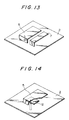
- an additional plate 7 is positioned adjacent to the radiator 5, as shown in Figure 13.
- an antenna includes an impedance compensating element 12 additionally connected with the feed line of the antenna to increase the resonant frequency band width such that the impedance matching with the feed line is provided ( Figure 14).
- This broadband microstrip antenna comprises at least two sheet radiators having the same resonant frequency and having their radiating edges spaced parallel to each other to provide capacitive coupling between them. Both radiators are fed in a well-known manner which substantially is not effecting an increase of the bandwidth.
- the broadband performance of this microstrip antenna is optimized up to a certain degree but does not meet all of the substantial requirements for mobile radio communication.
- the two way simultaneous transmission and reception system for automobiles which is intended by the present invention, has an antenna surrounded by various automobile components by which the transmission and reception of the antenna would be adversely affected. It is therefore desired to provide a radio communication antenna which has a widened band width with a degree of freedom for stabilizing the transmission and reception even under the above circumstances.
- the present invention which is defined by claims 1 and 11 provides a wide band antenna system for mobile communications, comprising a ground plate having a flat surface, an L-shaped radiator plate having one leg of L arranged parallel to said ground plate with the other leg being positioned perpendicular to said ground plate, said radiator plate being disposed having a gap between the lower end of said vertical leg and the upper surface of said ground plate, a coaxial feed cable for connecting said ground plate with an outer conductor and also for connecting an inner conductor with substantially the center of said vertical leg end of said radiator plate, and an additional conductive no-feed element (sub-radiator) formed by an L-shaped plate rigidly mounted on said ground plate at a position in close proximity to said radiator plate, said sub-radiator having one leg extending parallel to said ground plate with the end thereof being spaced away from the end of the parallel leg of said radiator plate by a given distance, the vertical leg of said L-shaped plate having the end connected with said ground plate to provide an increased band width.
- a ground plate having a flat surface
- the opened end of the radiator plate is located opposite to that of the sub-radiator with a given spacing therebetween.
- This is intended to utilize the variations of a feed point impedance due to a current induced in the sub-radiator to provide a very widened frequency band in which the real part of the impedance can be maintained, at the same value as or a value very near to the impedance of the feed line (normally equal to 50 Ohms) under a resonant condition (or when the imaginary part of the impedance is equal zero).
- the antenna system of the present invention there is further a given gap between the lower end of the radiator plate connected with feed line and the upper surface of the ground plate.
- a gap provides a capacitance functioning to offset a reactance component corresponding to the imaginary part of the impedance of the antenna.
- the imaginary part of the impedance could be maintained substantially at zero or a value substantially equal to zero over the widened frequency band width.
- Figure 2 shows the relationship between the real and imaginary parts of the feed point impedance of the antenna, relative to a frequency used by the aforementioned antenna system which is constructed according to the present invention.
- the frequency band matching the impedance of the feed line 50 Ohms
- the resonant frequency band can be increased sufficiently.
- the antenna system can have a widened frequency band (resonant frequency band) in which the sufficient number of different frequency bands can be included, since the antenna system comprises a radiator plate having its opened end opposed to the opened end of a sub-radiator element, the impedance of the feed point being regulated to create a dual resonance by the use of a current induced in the sub-radiator element. Accordingly, the transmission and reception can be carried out satisfactorily even though the antenna is adversely affected to shift the resonant frequency band by any external factor.
- the antenna system of the present invention could have a fractional resonant frequency band width of 30% or higher which could match the impedance in the feed line.
- the antenna system is of a very simplified construction and can easily realize a matching in a desired ferequency band by modifying the size and shape of the antenna.
- the antenna system may be applied to various applications and is optimum for a transmitter and receiver antenna which is to be mounted on any vehicle such as automobile or the like.
- the antenna system of the present invention can be reduced in size.
- the entire antenna system can be reduced in size by the fact that a dielectric material is interposed between the radiator plate and the ground plate and between the sub-radiator element and the ground plate.
- the relative dielectric constant of the dielectric material used in the antenna system of the present invention is ⁇ r
- the shortening coefficient of wave-length is approximately represented by 1/ ⁇ ⁇ r ⁇ . This means that the effective resonant length of the antenna can be shortened by using a dielectric material having its increased relative dielectric constant.
- the present invention preferably uses a material having its increased relative dielectric constant such as epoxy resin, Teflon, glass or the like.
- Figure 1 is a schematic view showing the first embodiment of the present invention.
- Figure 2 is a graph showing the variations of real and imaginary parts of the antenna feed point impedance relative to various frequencies.
- Figure 3 is a graph showing the return loss characteristic of the antenna in the first embodiment of the present invention.
- Figure 4 is a graph showing the return loss characteristic of the antenna in the second embodiment of the present invention.
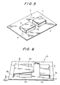
- Figure 5 is a schematic view of the third embodiment of the present invention.
- Figure 6 is a schematic view of the fourth embodiment of the present invention in which a radiator plate is supported by a supporter relative to a ground plate.
- FIG. 7 is a cross-sectional view of the fifth embodiment of the present invention in which a radiator plate is spaced away from a ground plate by a given gap and rigidly supported on the ground plate by means of a molding resin.
- Figure 8 is a schematic view of the sixth embodiment of the present invention in which a radiator plate and a sub-radiator element are molded by a supporter having sloping outer wall faces.
- Figure 9 is a corss-sectional view of the sixth embodiment shown in the Fig. 8.
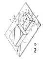
- Figure 10 is a schematic view of the seventh embodiment of the present invention in which a sub-radiator element is electrically connected with a ground plate through a narrow bridge portion.
- FIGS 11, 12, 13 and 14 are schematic views showing various antenna configurations in the prior art.
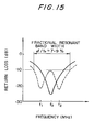
- Figure 15 is a graph showing the variations of return loss relative to various frequencies in an antenna system constructed according to the prior art.
- an antenna 1 for vehicles which is adapted to be mounted on an automobile body and to perform the transmission and reception of radio waves between the automobile and a radio base station.
- the antenna 1 comprises a ground plate 2 formed of a flat conductive plate.
- the ground plate 2 includes an opening 3 formed therethrough.
- the opening 3 receives an inner conductor (core wire) 4b of a coaxial feed cable 4 without electrical connection while the inner edge of the opening 3 is electrically connected with an outer conductor 4a of the coaxial cable 4.
- the radiator plate 5 is formed of an L-shaped conductive plate with one leg 5a being positioned parallel to the ground plate 3.
- the other or vertival leg 5b of the radiator plate 5 has one edge 5c spaced apart from the ground plate 2 by a given narrow gap 6 (g1 ).
- the edge 5c of the radiator plate 5 is electrically connected substantially at its center with the inner conductor 4b of the coaxial feed cable 4.
- a sub-radiator element 7 formed of an L-shaped conductive plate is mounted on the ground plate in proximity to the radiator plate 5 with one leg 7a being positioned parallel to the ground plate 2.
- the one leg 7a of the sub-radiator element 7 is located opposed to the end 5d of the radiator plate 5 with a given gap 8 (g2) therebetween.
- the other or vertical leg 7c of the sub-radiator element 7 has one end 7d connected with the ground plate 2.
- the length L1 of the radiator plate 5 measured from the feed end 4b of the coaxial cable 4 to the end 5d of the radiator plate 5 is set to be slightly larger than one-fourth the wave-length ⁇ used herein while the length L2 of the sub-radiator element 7 is selected to be slightly smaller than one-fourth the wave-length ⁇ used herein.
- the antenna having the aforementioned dimensions has return loss characterisitics shown in Figure 3.
- the fractional resonant band exceeds 20% in the first embodiment of the present invention.
- the fractional resonant band could be inceased to 40% if the heights H1 and H2 of the radiator and sub-radiator plates were increased up to 30 mm respectively.
- a further increased band width can be realized by regulating the widths (W11, W12; W21, W22) of the radiator and sub-radiator plates in the antenna system.
- the antenna system having the above dimensions has return loss characteristics shown in Figure 4. It can be seen from this figure that the fractional resonant band becomes 30% or more.
- the first and second embodiments of the present inventon can provide an antenna system having an increased degree of freedom which provide a widened frequency band width (resonant frequency band width) by modifying the size and shape of the antenna.
- FIG. 5 there is shown in the third embodiment providing an antenna system 1 which is further reduced in size and has an increased mechanical strength.
- fillers each formed of a dielectric material having its good high-frequency characteristics, such as Teflon, epoxy resin, glass or the like are interposed between the ground plate 2 and the radiator plate 5 and between the ground plate 2 and the sub-radiator element 7.
- the size of the entire antenna could be reduced up to about 20%.
- the interposition of the fillers 9 permits the antenna system to withstand vibrations from the vehicle on which it is mounted.
- Figure 6 shows the fourth embodiment of the present invention having a structure similar to that of the first embodiment shown in Figure 1, wherein an L-shaped radiator plate 5 is floated above a ground plate 2 with a gap 6 (g1) formed therebetween.
- the radiator plate 5 has one leg 5a placed on a supporter 20 parallel to the ground plate 2. Such an arrangement supports the radiator plate 5 above the ground plate 2 while maintaining the gap 6 (g1) properly.
- the supporter 20 is preferably made of any suitable electrically insulating material such as foamed styrene or the like.
- FIG. 7 shows the fifth embodiment of the present invention in which an antenna system 1 is mounted within a casing.
- the casing comprises a base plate 21 and a closure 22, both of which are made of any suitable electrically insulating material such as plastic material or the like.
- a ground plate 2 is rigidly mounted on the base plate 21 by any suitable joining means such as adhesion or the like.
- the base plate 21 also rigidly supports a coaxial cable 4 by clip means such that the coaxial cable 4 is introduced into the casing.
- the coaxial cable 4 includes an outer conductor 4a joined to the ground plate 2 and an inner conductor 4b connected with the vertical leg 5b of an L-shaped radiator plate 5 at its edge.
- an L-shaped sub-radiator element 7 has its vertical leg 7c rigidly connected at one end with the ground plate 2 by any suitable joining means such as welding or the like.
- a molding resin 24 is charged into the casing such that the radiator plate 5 is rigidly mounted on the ground plate 2 with a gap 6 (g1) formed therebetween.
- the molding resin is preferably of foamed styrene or Teflon.
- the radiator plate 5 can be properly positioned relative to the ground plate 2 with the gap formed therebetween, by the use of the molding resin.
- Figures 8 and 9 show the sixth embodiment of the present invention in which an L-shaped radiator plate 5 and a similar L-shaped sub-radiator element 7 are supported on a ground plate 2 by means of fillers 9 and further covered by supporter 20 having the shape of a frustum of a pyramid.
- the fillers are made of dielectric material which has good high-frequency characteristics. Teflon, epoxy resin or glass are preferable to provide such dielectric material. Molded resin is interposed between the ground plate 2 and the radiator plate 5 to make a slightly narrow channel therebetween for supporting the radiator plate 5 in separated disposition above the ground plate 2.
- the sub-radiator element 7 is rigidly mounted on the ground plate 2 with the parallel leg thereof being opposed to the parallel leg of the radiator plate 5. The spaced room between the sub-radiator 7 and the ground plate 2 is then filled with molded resin for increasing the dieletric constant of the sub-radiator.
- the antenna of the embodiment is further molded by supporter 20 being made of foamed styren for example to solidify the shape of the antenna. Molding the supporter 20 provides the external shape of a frustum of a pyramid to the antenna in which the upper surfaces of the radiator plate 5 and the sub-radiator element 7 are exposed outwardly. Such a frustum of a pyramid shaped supporter 20 can protect the antenna from collision or mechanical shock. As shown in figures the molding supporter 20 can cover the radiator plate 5 and the sub-radiator element 7 except their upper surfaces for securely mounting the plate 5 and the element 7 on the ground plate 2.
- the supporter 20 has sloping outer wall faces on its four sides so as to provide the rounding off shape on the outer surface thereof.
- the above mentioned shape is preferable to realize a well-formed design for an antenna equipment being placed on the back seat tray of the automobiles.
- Figure 10 shows the seventh embodiment of the present invention which is similar to the third embodiment shown in Fig. 5.
- the sub-radiator element 7 of the present embodiment has a connecting bridge portion 7e for making an electrical conductivity between the sub-radiator 7 and the ground plate 2 within a restricted narrow path. Accordingly the remainder of the end portion 7d of the sub-radiator element 7 is kept in electrically insulated relation to the ground plate 2.
- the bridge portion 7e is preferably provided on one side of the vertical leg 7c of the sub-radiator element 7.
- the seventh embodiment shown in Fig. 10 can provide an antenna having a widened resonant band width.
- the bridge portion 7e of the shown embodiment is composed in the projected portion from the vertical leg 7c of the element 7, the bridge of this invention can be formed by a solder conductivity path, a lead wire or the like.
Landscapes
- Details Of Aerials (AREA)
- Waveguide Aerials (AREA)
Claims (12)
- Une structure d'antenne (1) pour des véhicules, comprenant
une plaque de masse (2) ayant une surface plane, une plaque rayonnante en forme de L (5) ayant une branche (5a) du L disposée parallèlement à la plaque de masse (2), et l'autre branche (5b) verticale et placée perpendiculairement à la plaque de masse (2), et
un élément rayonnant auxiliaire (7) formé par une plaque en forme de L montée de façon rigide sur la plaque de masse (2) en une position proche de la plaque rayonnante (5),
cet élément rayonnant auxiliaire (7) ayant une branche (7a) qui s'étend parallèlement à la plaque de masse (2) avec son extrémité (7b) espacée d'une distance donnée (8g2) par rapport à l'extrémité (5d) de la branche parallèle (5a) de la plaque rayonnante (5),
l'extrémité (7d) d'une branche verticale (7c) de la plaque en forme de L (7) étant reliée à la plaque de masse (2),
caractérisée par
le fait que la plaque rayonnante est disposée de façon qu'un espace étroit (6g1) soit formé entre l'extrémité inférieure (5c) de la branche verticale (5b) et la surface supérieure de la plaque de masse,
un câble coaxial d'alimentation (4) pour connecter la plaque de masse à un conducteur extérieur (4a), et également pour connecter un conducteur intérieur (4b) avec pratiquement le centre de l'extrémité inférieure de la branche verticale (5c) de la plaque rayonnante, pour donner une largeur de bande de résonance accrue. - Une structure d'antenne selon la revendication 1, comprenant en outre des moyens de remplissage (24) destinés à entourer la plaque de masse (2), la plaque rayonnante (5) et l'élément rayonnant auxiliaire (7), ces moyens de remplissage étant constitués par une matière diélectrique qui présente de bonnes caractéristiques en haute fréquence.
- Une structure d'antenne selon la revendication 1, dans laquelle les moyens de remplissage (9, 24) sont au moins intercalés entre la plaque de masse (2) et la plaque rayonnante (5) et entre la plaque de masse (2) et l'élément rayonnant auxiliaire (7).
- Une structure d'antenne selon la revendication 3, dans laquelle les moyens de remplissage sont constitués par une matière sélectionnée parmi le Téflon, la résine époxy ou le verre.
- Une structure d'antenne selon la revendication 3, comprenant en outre des moyens de support (20) qui recouvrent la partie de surface extérieure de la plaque rayonnante (5) et de l'élément rayonnant auxiliaire (7), pour monter de façon rigide la plaque rayonnante et la plaque d'élément rayonnant auxiliaire sur la plaque de masse (2).
- Une structure d'antenne selon la revendication 5, dans lequel la surface extérieure des moyens de support (20) présente des faces de paroi extérieure en pente, pour éviter que cette surface extérieure ne forme des angles vifs.
- Une structure d'antenne selon la revendication 1, comprenant en outre des moyens de support (20, 24) pour monter de façon rigide la plaque rayonnante (5) sur la plaque de masse (2) avec l'extrémité de la branche verticale (5b) de la plaque rayonnante (5) flottant au-dessus de la plaque de masse (2) en étant séparée de cette dernière par un espace étroit donné (6g1), les moyens de support étant constitués par un matériau électriquement isolant.
- Une structure d'antenne selon la revendication 6 ou 7, dans laquelle les moyens de support consistent en mousse de styrène.
- Une structure d'antenne selon la revendication 7, dans laquelle les moyens de support (24) comprennent une résine de moulage qui est disposée de façon à entourer la plaque rayonnante (5) et l'élément rayonnant auxiliaire (7), avec la plaque rayonnante (5) séparée de la plaque de masse par l'espace étroit donné (6g1) précité.
- Une structure d'antenne selon l'une quelconque des revendications 1 à 9, dans laquelle la longueur (L₁) de la plaque rayonnante (5) est fixée de façon à être légèrement supérieure au quart de la longueur d'onde λ d'une porteuse, et dans laquelle la longueur (L₂) de l'élément rayonnant auxiliaire (7) est fixée de façon à être légèrement inférieure au quart de la longueur d'onde λ de la porteuse.
- Une structure d'antenne pour des véhicules, comprenant
une plaque de masse (2) ayant une surface plane, une plaque rayonnante en forme de L (5) ayant une branche (5a) du L disposée parallèlement à la plaque de masse (2), tandis que l'autre branche (5b), qui est verticale, est disposée perpendiculairement à la plaque de masse (2), et
un élément rayonnant auxiliaire (7) formé par une plaque en forme de L qui est disposée à proximité de la plaque de masse (2), dans une position adjacente à la plaque rayonnante (5),
cet élément rayonnant auxiliaire (7) ayant une branche (7a) qui s'étend parallèlement à la plaque de masse (2) avec son extrémité (7b) espacée d'une distance donnée (8g2) par rapport à l'extrémité (5d) de la branche parallèle (5a) de la plaque rayonnante (5), et cet élément rayonnant auxiliaire ayant également une branche verticale (7c),
caractérisée en ce que
la plaque rayonnante est dispcsée de façon qu'il existe un espace étroit (6g1) entre l'extrémité inférieure (5c) de la branche verticale (5b) et la surface supérieure de la plaque de masse, et en qu'un câble coaxial d'alimentation (4) est incorporé pour connecter la plaque de masse à un conducteur extérieur (4a) et également pour connecter un conducteur intérieur (4b) avec pratiquement le centre de l'extrémité (5c) de la branche verticale de la plaque rayonnante, et
la branche verticale (7c) de la plaque en forme de L (7) comporte une partie de pont de connexion (7e) qui est connectée de façon rigide à la plaque de masse (2), d'un côté de la branche verticale, pour augmenter une largeur de bande de résonance. - Une structure d'antenne selon la revendication 11, comprenant en outre des moyens de remplissage (9) qui sont destinés à entourer la plaque de masse (2), la plaque rayonnante (5) et l'élément rayonnant auxiliaire (7), ces moyens de remplissage étant constitués par une matière diélectrique qui a de bonnes caractéristiques en haute fréquence, dans laquelle la longueur (L₁) de la plaque rayonnante (7) est fixée de façon à être légèrement supérieure au quart de la longueur d'onde λ d'une porteuse, et dans laquelle la longueur (L₂) de l'élément rayonnant auxiliaire (7) est fixée de façon à être légèrement inférieure au quart de la longueur d'onde λ de la porteuse.
Applications Claiming Priority (2)
| Application Number | Priority Date | Filing Date | Title |
|---|---|---|---|
| JP57206/88 | 1988-03-10 | ||
| JP63057206A JPH0659009B2 (ja) | 1988-03-10 | 1988-03-10 | 移動体用アンテナ |
Publications (3)
| Publication Number | Publication Date |
|---|---|
| EP0332139A2 EP0332139A2 (fr) | 1989-09-13 |
| EP0332139A3 EP0332139A3 (en) | 1990-07-18 |
| EP0332139B1 true EP0332139B1 (fr) | 1993-09-15 |
Family
ID=13049032
Family Applications (1)
| Application Number | Title | Priority Date | Filing Date |
|---|---|---|---|
| EP89104001A Expired - Lifetime EP0332139B1 (fr) | 1988-03-10 | 1989-03-07 | Antenne à large bande pour communications mobiles |
Country Status (5)
| Country | Link |
|---|---|
| US (1) | US4907006A (fr) |
| EP (1) | EP0332139B1 (fr) |
| JP (1) | JPH0659009B2 (fr) |
| CA (1) | CA1313408C (fr) |
| DE (1) | DE68909072T2 (fr) |
Cited By (11)
| Publication number | Priority date | Publication date | Assignee | Title |
|---|---|---|---|---|
| US8004470B2 (en) | 2004-06-28 | 2011-08-23 | Pulse Finland Oy | Antenna, component and methods |
| US8466756B2 (en) | 2007-04-19 | 2013-06-18 | Pulse Finland Oy | Methods and apparatus for matching an antenna |
| US8473017B2 (en) | 2005-10-14 | 2013-06-25 | Pulse Finland Oy | Adjustable antenna and methods |
| US8564485B2 (en) | 2005-07-25 | 2013-10-22 | Pulse Finland Oy | Adjustable multiband antenna and methods |
| US8618990B2 (en) | 2011-04-13 | 2013-12-31 | Pulse Finland Oy | Wideband antenna and methods |
| US8629813B2 (en) | 2007-08-30 | 2014-01-14 | Pusle Finland Oy | Adjustable multi-band antenna and methods |
| US8648752B2 (en) | 2011-02-11 | 2014-02-11 | Pulse Finland Oy | Chassis-excited antenna apparatus and methods |
| US8786499B2 (en) | 2005-10-03 | 2014-07-22 | Pulse Finland Oy | Multiband antenna system and methods |
| US8847833B2 (en) | 2009-12-29 | 2014-09-30 | Pulse Finland Oy | Loop resonator apparatus and methods for enhanced field control |
| US9406998B2 (en) | 2010-04-21 | 2016-08-02 | Pulse Finland Oy | Distributed multiband antenna and methods |
| US9450291B2 (en) | 2011-07-25 | 2016-09-20 | Pulse Finland Oy | Multiband slot loop antenna apparatus and methods |
Families Citing this family (128)
| Publication number | Priority date | Publication date | Assignee | Title |
|---|---|---|---|---|
| JPH02308604A (ja) * | 1989-05-23 | 1990-12-21 | Harada Ind Co Ltd | 移動通信用平板アンテナ |
| JPH03219705A (ja) * | 1989-11-15 | 1991-09-27 | Matsushita Electric Works Ltd | トップローディングアンテナ |
| JP2870940B2 (ja) * | 1990-03-01 | 1999-03-17 | 株式会社豊田中央研究所 | 車載アンテナ |
| DE4022072A1 (de) * | 1990-07-11 | 1992-01-16 | Michael Woelfelschneider | Reflektor-antenne in microstriptechnik |
| JP3308558B2 (ja) * | 1991-05-02 | 2002-07-29 | 富士通株式会社 | アンテナモジュール |
| US5200756A (en) * | 1991-05-03 | 1993-04-06 | Novatel Communications Ltd. | Three dimensional microstrip patch antenna |
| US5355142A (en) * | 1991-10-15 | 1994-10-11 | Ball Corporation | Microstrip antenna structure suitable for use in mobile radio communications and method for making same |
| US5206626A (en) * | 1991-12-24 | 1993-04-27 | Knogo Corporation | Stabilized article surveillance responder |
| US5467095A (en) * | 1992-06-19 | 1995-11-14 | Rodal; Eric B. | Low profile antenna |
| US5319378A (en) * | 1992-10-09 | 1994-06-07 | The United States Of America As Represented By The Secretary Of The Army | Multi-band microstrip antenna |
| DE4239785A1 (de) * | 1992-11-26 | 1994-06-01 | Forschungsgesellschaft Fuer In | Gruppenantenne in Streifenleitertechnik |
| FR2699740B1 (fr) * | 1992-12-23 | 1995-03-03 | Patrice Brachat | Antenne large bande à encombrement réduit, et dispositif d'émission et/ou de réception correspondant. |
| US5400040A (en) * | 1993-04-28 | 1995-03-21 | Raytheon Company | Microstrip patch antenna |
| JPH0750508A (ja) * | 1993-08-06 | 1995-02-21 | Fujitsu Ltd | アンテナモジュール |
| JP3326935B2 (ja) * | 1993-12-27 | 2002-09-24 | 株式会社日立製作所 | 携帯無線機用小型アンテナ |
| GB9410557D0 (en) * | 1994-05-26 | 1994-07-13 | Schlumberger Ind Ltd | Radio antennae |
| US5471221A (en) * | 1994-06-27 | 1995-11-28 | The United States Of America As Represented By The Secretary Of The Army | Dual-frequency microstrip antenna with inserted strips |
| GB9417450D0 (en) | 1994-08-25 | 1994-10-19 | Symmetricom Inc | An antenna |
| US5510804A (en) * | 1994-10-03 | 1996-04-23 | Ford Motor Company | F-shaped three element dipole antenna for motor vehicles |
| DE19504577A1 (de) * | 1995-02-11 | 1996-08-14 | Fuba Automotive Gmbh | Flachantenne |
| US5631659A (en) * | 1995-03-17 | 1997-05-20 | Lucent Technologies Inc. | Microstrip patch antennas with radiation control |
| DE59501555D1 (de) * | 1995-04-20 | 1998-04-09 | Fuba Automotive Gmbh | Flachantennen-Anordnung |
| FR2739225B1 (fr) * | 1995-09-27 | 1997-11-14 | Cga Hbs | Element d'antenne a hyperfrequences |
| JP3114582B2 (ja) * | 1995-09-29 | 2000-12-04 | 株式会社村田製作所 | 表面実装型アンテナおよびこれを用いた通信機 |
| US5748149A (en) * | 1995-10-04 | 1998-05-05 | Murata Manufacturing Co., Ltd. | Surface mounting antenna and antenna apparatus |
| US5675345A (en) * | 1995-11-21 | 1997-10-07 | Raytheon Company | Compact antenna with folded substrate |
| US6087988A (en) * | 1995-11-21 | 2000-07-11 | Raytheon Company | In-line CP patch radiator |
| US5898404A (en) * | 1995-12-22 | 1999-04-27 | Industrial Technology Research Institute | Non-coplanar resonant element printed circuit board antenna |
| JP3319268B2 (ja) * | 1996-02-13 | 2002-08-26 | 株式会社村田製作所 | 表面実装型アンテナおよびこれを用いた通信機 |
| JP3296189B2 (ja) * | 1996-06-03 | 2002-06-24 | 三菱電機株式会社 | アンテナ装置 |
| US5841401A (en) * | 1996-08-16 | 1998-11-24 | Raytheon Company | Printed circuit antenna |
| JP3180683B2 (ja) * | 1996-09-20 | 2001-06-25 | 株式会社村田製作所 | 表面実装型アンテナ |
| DE19646100A1 (de) * | 1996-11-08 | 1998-05-14 | Fuba Automotive Gmbh | Flachantenne |
| FI110395B (fi) * | 1997-03-25 | 2003-01-15 | Nokia Corp | Oikosuljetuilla mikroliuskoilla toteutettu laajakaista-antenni |
| WO1998044588A1 (fr) * | 1997-03-31 | 1998-10-08 | Qualcomm Incorporated | Antenne a plaques a deux bandes de frequence comportant des elements actifs et passifs alternants |
| US6114996A (en) * | 1997-03-31 | 2000-09-05 | Qualcomm Incorporated | Increased bandwidth patch antenna |
| US6008762A (en) * | 1997-03-31 | 1999-12-28 | Qualcomm Incorporated | Folded quarter-wave patch antenna |
| US6151480A (en) * | 1997-06-27 | 2000-11-21 | Adc Telecommunications, Inc. | System and method for distributing RF signals over power lines within a substantially closed environment |
| US6184833B1 (en) | 1998-02-23 | 2001-02-06 | Qualcomm, Inc. | Dual strip antenna |
| GB9813002D0 (en) * | 1998-06-16 | 1998-08-12 | Symmetricom Inc | An antenna |
| EP0978729A3 (fr) * | 1998-08-07 | 2002-03-20 | Hitachi, Ltd. | Appareil d'émission-réception à haute fréquence pour applications comme système radar sur véhicule |
| SE513525C2 (sv) | 1998-11-20 | 2000-09-25 | Smarteq Ab | En antennanordning |
| GB9828768D0 (en) | 1998-12-29 | 1999-02-17 | Symmetricom Inc | An antenna |
| GB9902765D0 (en) | 1999-02-08 | 1999-03-31 | Symmetricom Inc | An antenna |
| GB9912441D0 (en) | 1999-05-27 | 1999-07-28 | Symmetricon Inc | An antenna |
| DE69941025D1 (de) * | 1999-07-09 | 2009-08-06 | Ipcom Gmbh & Co Kg | Zweibandfunkgerät |
| JP2001127525A (ja) | 1999-08-18 | 2001-05-11 | Alps Electric Co Ltd | アンテナ |
| CA2341736A1 (fr) * | 1999-09-09 | 2001-03-15 | Murata Manufacturing Co | Antenne montee en surface et dispositif de communication comprenant cette antenne |
| FI114254B (fi) * | 2000-02-24 | 2004-09-15 | Filtronic Lk Oy | Tasoantennirakenne |
| JP3640595B2 (ja) * | 2000-05-18 | 2005-04-20 | シャープ株式会社 | 積層パターンアンテナ及びそれを備えた無線通信装置 |
| WO2001091233A1 (fr) * | 2000-05-23 | 2001-11-29 | Telefonaktiebolaget Lm Ericsson (Publ) | Antenne multibande |
| EP1168491B1 (fr) * | 2000-05-23 | 2007-01-24 | Telefonaktiebolaget LM Ericsson (publ) | Antenne pour plusieurs fréquences |
| JP2002050924A (ja) * | 2000-08-01 | 2002-02-15 | Sansei Denki Kk | 広帯域内蔵アンテナ、および、その構成方法 |
| WO2002013306A1 (fr) * | 2000-08-08 | 2002-02-14 | Koninklijke Philips Electronics N.V. | Terminal sans fil |
| DE60120089T2 (de) * | 2000-11-22 | 2007-01-04 | Matsushita Electric Industrial Co., Ltd., Kadoma | Antenne und drahtloses Gerät mit einer solchen Antenne |
| JP2002299933A (ja) * | 2001-04-02 | 2002-10-11 | Murata Mfg Co Ltd | アンテナの電極構造およびそれを備えた通信機 |
| JP3629448B2 (ja) | 2001-07-27 | 2005-03-16 | Tdk株式会社 | アンテナ装置及びそれを備えた電子機器 |
| JP2003158419A (ja) * | 2001-09-07 | 2003-05-30 | Tdk Corp | 逆fアンテナ及びその給電方法並びにそのアンテナ調整方法 |
| JP2005531177A (ja) * | 2002-06-25 | 2005-10-13 | フラクトゥス・ソシエダッド・アノニマ | ハンドヘルド端末装置用マルチバンドアンテナ |
| JP3812503B2 (ja) * | 2002-06-28 | 2006-08-23 | 株式会社デンソー | 車両用アンテナの搭載構造および車両用アンテナの搭載方法 |
| EP1547194A1 (fr) | 2002-09-10 | 2005-06-29 | Fractus, S.A. | Antennes multibandes couplees |
| US7202826B2 (en) * | 2002-09-27 | 2007-04-10 | Radiall Antenna Technologies, Inc. | Compact vehicle-mounted antenna |
| JP2004129062A (ja) * | 2002-10-04 | 2004-04-22 | Sharp Corp | 周波数共用アンテナ |
| EP1443595A1 (fr) * | 2003-01-17 | 2004-08-04 | Sony Ericsson Mobile Communications AB | Antenne |
| WO2004066439A1 (fr) * | 2003-01-17 | 2004-08-05 | Sony Ericsson Mobile Communication Ab | Antenne |
| JP2005064938A (ja) | 2003-08-14 | 2005-03-10 | Nec Access Technica Ltd | 小型無線機用アンテナ装置 |
| JP2005269301A (ja) * | 2004-03-19 | 2005-09-29 | Nec Corp | 内蔵アンテナおよびこれを有する電子機器 |
| JP3852113B2 (ja) * | 2004-03-31 | 2006-11-29 | 東陶機器株式会社 | マイクロストリップアンテナ及び高周波センサ |
| JP4063833B2 (ja) * | 2004-06-14 | 2008-03-19 | Necアクセステクニカ株式会社 | アンテナ装置及び携帯無線端末 |
| JP2006186851A (ja) * | 2004-12-28 | 2006-07-13 | Toshiba Corp | アンテナ装置 |
| KR100787229B1 (ko) | 2005-02-04 | 2007-12-21 | 삼성전자주식회사 | 이중 대역 역 에프 평판안테나 |
| JP4308786B2 (ja) * | 2005-02-24 | 2009-08-05 | パナソニック株式会社 | 携帯無線機 |
| EP1859507A4 (fr) * | 2005-03-16 | 2012-08-15 | Lk Products Oy | Composant d antenne |
| US7733279B2 (en) * | 2005-04-07 | 2010-06-08 | Behzad Tavassoli Hozouri | Multi-band or wide-band antenna including driven and parasitic top-loading elements |
| US7242352B2 (en) * | 2005-04-07 | 2007-07-10 | X-Ether, Inc, | Multi-band or wide-band antenna |
| JP4820671B2 (ja) * | 2005-06-28 | 2011-11-24 | ミツミ電機株式会社 | 複合アンテナ装置 |
| US7505008B2 (en) * | 2005-09-26 | 2009-03-17 | Electronics And Telecommunications Research Institute | Electrical loop antenna with unidirectional and uniform current radiation source |
| FI119535B (fi) | 2005-10-03 | 2008-12-15 | Pulse Finland Oy | Monikaistainen antennijärjestelmä |
| FI118872B (fi) | 2005-10-10 | 2008-04-15 | Pulse Finland Oy | Sisäinen antenni |
| FI118837B (fi) | 2006-05-26 | 2008-03-31 | Pulse Finland Oy | Kaksoisantenni |
| KR100815736B1 (ko) * | 2006-07-28 | 2008-03-20 | 주식회사 포스코 | 금속환경을 위한 rfid 태그 안테나 및 이를 이용한rfid 태그 |
| JP5114045B2 (ja) * | 2006-11-27 | 2013-01-09 | 日本電気株式会社 | アンテナ装置及び携帯無線端末 |
| TWI330905B (en) * | 2006-12-28 | 2010-09-21 | Yageo Corp | Antenna for gps |
| US10211538B2 (en) | 2006-12-28 | 2019-02-19 | Pulse Finland Oy | Directional antenna apparatus and methods |
| JP2008199113A (ja) * | 2007-02-08 | 2008-08-28 | Toshiba Corp | マイクロストリップアンテナおよびマイクロストリップアンテナ組立体 |
| WO2008126724A1 (fr) * | 2007-04-05 | 2008-10-23 | Murata Manufacturing Co., Ltd. | Antenne et dispositif de radiocommunication |
| KR101323853B1 (ko) * | 2007-07-16 | 2013-10-31 | 삼성전자주식회사 | 평판형 역 에프 안테나 |
| TWM330583U (en) * | 2007-09-13 | 2008-04-11 | Wistron Neweb Corp | Wide-band antenna and related dual-band antenna |
| JP4970206B2 (ja) * | 2007-09-21 | 2012-07-04 | 株式会社東芝 | アンテナ装置 |
| US7999744B2 (en) * | 2007-12-10 | 2011-08-16 | City University Of Hong Kong | Wideband patch antenna |
| EP2107639A1 (fr) * | 2008-03-31 | 2009-10-07 | Laird Technologies AB | Dispositif d'antenne doté d'une diversité de récepteurs et dispositif de communication radio portable comportant un tel dispositif d'antenne |
| FI20085304A0 (fi) | 2008-04-11 | 2008-04-11 | Polar Electro Oy | Resonaattorirakenne pienikokoisissa radiolaitteissa |
| US8085203B1 (en) | 2008-04-18 | 2011-12-27 | Aero Antenna Inc. | Ground surrounded non-resonant slot-like patch antenna |
| US8665170B2 (en) * | 2008-06-30 | 2014-03-04 | Tyco Electronics Corporation | Antenna assembly having multiple antenna elements with hemispherical coverage |
| JP5263383B2 (ja) * | 2009-02-20 | 2013-08-14 | 株式会社村田製作所 | アンテナ装置 |
| FI20096134A0 (fi) | 2009-11-03 | 2009-11-03 | Pulse Finland Oy | Säädettävä antenni |
| TWI409993B (zh) * | 2009-11-27 | 2013-09-21 | Quanta Comp Inc | Multi - frequency antenna |
| FI20096251A0 (sv) | 2009-11-27 | 2009-11-27 | Pulse Finland Oy | MIMO-antenn |
| WO2011096021A1 (fr) * | 2010-02-05 | 2011-08-11 | 三菱電機株式会社 | Dispositif à antenne à plaque raccourcie et son procédé de fabrication |
| FI20105158A7 (fi) | 2010-02-18 | 2011-08-19 | Pulse Finland Oy | Kuorisäteilijällä varustettu antenni |
| FI20115072A0 (fi) | 2011-01-25 | 2011-01-25 | Pulse Finland Oy | Moniresonanssiantenni, -antennimoduuli ja radiolaite |
| US9673507B2 (en) | 2011-02-11 | 2017-06-06 | Pulse Finland Oy | Chassis-excited antenna apparatus and methods |
| US8854265B1 (en) * | 2011-04-28 | 2014-10-07 | Airgain, Inc. | L-shaped feed for a matching network for a microstrip antenna |
| US8866689B2 (en) | 2011-07-07 | 2014-10-21 | Pulse Finland Oy | Multi-band antenna and methods for long term evolution wireless system |
| US9123990B2 (en) | 2011-10-07 | 2015-09-01 | Pulse Finland Oy | Multi-feed antenna apparatus and methods |
| US9531058B2 (en) | 2011-12-20 | 2016-12-27 | Pulse Finland Oy | Loosely-coupled radio antenna apparatus and methods |
| US9484619B2 (en) | 2011-12-21 | 2016-11-01 | Pulse Finland Oy | Switchable diversity antenna apparatus and methods |
| US8988296B2 (en) | 2012-04-04 | 2015-03-24 | Pulse Finland Oy | Compact polarized antenna and methods |
| US9979078B2 (en) | 2012-10-25 | 2018-05-22 | Pulse Finland Oy | Modular cell antenna apparatus and methods |
| US10069209B2 (en) | 2012-11-06 | 2018-09-04 | Pulse Finland Oy | Capacitively coupled antenna apparatus and methods |
| US10079428B2 (en) | 2013-03-11 | 2018-09-18 | Pulse Finland Oy | Coupled antenna structure and methods |
| US9647338B2 (en) | 2013-03-11 | 2017-05-09 | Pulse Finland Oy | Coupled antenna structure and methods |
| US9252502B2 (en) * | 2013-06-18 | 2016-02-02 | Telefonaktiebolaget L M Ericsson (Publ) | Inverted F-antennas at a wireless communication node |
| US9634383B2 (en) | 2013-06-26 | 2017-04-25 | Pulse Finland Oy | Galvanically separated non-interacting antenna sector apparatus and methods |
| US9680212B2 (en) | 2013-11-20 | 2017-06-13 | Pulse Finland Oy | Capacitive grounding methods and apparatus for mobile devices |
| US9590308B2 (en) | 2013-12-03 | 2017-03-07 | Pulse Electronics, Inc. | Reduced surface area antenna apparatus and mobile communications devices incorporating the same |
| US9350081B2 (en) | 2014-01-14 | 2016-05-24 | Pulse Finland Oy | Switchable multi-radiator high band antenna apparatus |
| US9973228B2 (en) | 2014-08-26 | 2018-05-15 | Pulse Finland Oy | Antenna apparatus with an integrated proximity sensor and methods |
| US9948002B2 (en) | 2014-08-26 | 2018-04-17 | Pulse Finland Oy | Antenna apparatus with an integrated proximity sensor and methods |
| US9722308B2 (en) | 2014-08-28 | 2017-08-01 | Pulse Finland Oy | Low passive intermodulation distributed antenna system for multiple-input multiple-output systems and methods of use |
| US9906260B2 (en) | 2015-07-30 | 2018-02-27 | Pulse Finland Oy | Sensor-based closed loop antenna swapping apparatus and methods |
| US10263341B2 (en) * | 2016-04-19 | 2019-04-16 | Ethertronics, Inc. | Low profile antenna system |
| CN112928445B (zh) | 2019-12-06 | 2023-01-10 | 北京小米移动软件有限公司 | 天线结构和电子设备 |
| WO2021153035A1 (fr) * | 2020-01-30 | 2021-08-05 | 株式会社村田製作所 | Dispositif antenne |
| US12176631B1 (en) * | 2020-08-06 | 2024-12-24 | Bae Systems Space & Mission Systems Inc. | Electrically small wideband resonant loop antenna systems and methods |
| US20240170845A1 (en) * | 2021-03-25 | 2024-05-23 | Yokowo Co., Ltd. | Antenna device |
| US12316013B1 (en) | 2021-05-27 | 2025-05-27 | Bae Systems Space & Mission Systems Inc. | Ultra-broadband current sheet array |
| US12548912B2 (en) * | 2022-07-01 | 2026-02-10 | Kabushiki Kaisha Tokai Rika Denki Seisakusho | Metal plate antenna and antenna device |
Family Cites Families (8)
| Publication number | Priority date | Publication date | Assignee | Title |
|---|---|---|---|---|
| US4326203A (en) * | 1975-04-24 | 1982-04-20 | The United States Of America As Represented By The Secretary Of The Navy | Corner fed electric non rectangular microstrip dipole antennas |
| GB2067842B (en) * | 1980-01-16 | 1983-08-24 | Secr Defence | Microstrip antenna |
| JPS58104504A (ja) * | 1981-12-16 | 1983-06-22 | Matsushita Electric Ind Co Ltd | 無線機用アンテナ |
| US4605933A (en) * | 1984-06-06 | 1986-08-12 | The United States Of America As Represented By The Secretary Of The Navy | Extended bandwidth microstrip antenna |
| JPH0669122B2 (ja) * | 1984-08-01 | 1994-08-31 | 日本電信電話株式会社 | 広帯域伝送線路アンテナ |
| JPS6259922A (ja) * | 1985-09-10 | 1987-03-16 | Canon Inc | 強誘電性液晶素子 |
| JPS62209904A (ja) * | 1986-03-11 | 1987-09-16 | Nec Corp | 小形無線機用アンテナ装置 |
| GB2198290B (en) * | 1986-11-29 | 1990-05-09 | Stc Plc | Dual band circularly polarised antenna with hemispherical coverage |
-
1988
- 1988-03-10 JP JP63057206A patent/JPH0659009B2/ja not_active Expired - Fee Related
-
1989
- 1989-03-07 EP EP89104001A patent/EP0332139B1/fr not_active Expired - Lifetime
- 1989-03-07 DE DE89104001T patent/DE68909072T2/de not_active Expired - Fee Related
- 1989-03-09 US US07/321,271 patent/US4907006A/en not_active Expired - Fee Related
- 1989-03-09 CA CA000593188A patent/CA1313408C/fr not_active Expired - Fee Related
Cited By (12)
| Publication number | Priority date | Publication date | Assignee | Title |
|---|---|---|---|---|
| US8004470B2 (en) | 2004-06-28 | 2011-08-23 | Pulse Finland Oy | Antenna, component and methods |
| US8390522B2 (en) | 2004-06-28 | 2013-03-05 | Pulse Finland Oy | Antenna, component and methods |
| US8564485B2 (en) | 2005-07-25 | 2013-10-22 | Pulse Finland Oy | Adjustable multiband antenna and methods |
| US8786499B2 (en) | 2005-10-03 | 2014-07-22 | Pulse Finland Oy | Multiband antenna system and methods |
| US8473017B2 (en) | 2005-10-14 | 2013-06-25 | Pulse Finland Oy | Adjustable antenna and methods |
| US8466756B2 (en) | 2007-04-19 | 2013-06-18 | Pulse Finland Oy | Methods and apparatus for matching an antenna |
| US8629813B2 (en) | 2007-08-30 | 2014-01-14 | Pusle Finland Oy | Adjustable multi-band antenna and methods |
| US8847833B2 (en) | 2009-12-29 | 2014-09-30 | Pulse Finland Oy | Loop resonator apparatus and methods for enhanced field control |
| US9406998B2 (en) | 2010-04-21 | 2016-08-02 | Pulse Finland Oy | Distributed multiband antenna and methods |
| US8648752B2 (en) | 2011-02-11 | 2014-02-11 | Pulse Finland Oy | Chassis-excited antenna apparatus and methods |
| US8618990B2 (en) | 2011-04-13 | 2013-12-31 | Pulse Finland Oy | Wideband antenna and methods |
| US9450291B2 (en) | 2011-07-25 | 2016-09-20 | Pulse Finland Oy | Multiband slot loop antenna apparatus and methods |
Also Published As
| Publication number | Publication date |
|---|---|
| DE68909072D1 (de) | 1993-10-21 |
| EP0332139A2 (fr) | 1989-09-13 |
| EP0332139A3 (en) | 1990-07-18 |
| US4907006A (en) | 1990-03-06 |
| DE68909072T2 (de) | 1994-03-24 |
| JPH01231404A (ja) | 1989-09-14 |
| JPH0659009B2 (ja) | 1994-08-03 |
| CA1313408C (fr) | 1993-02-02 |
Similar Documents
| Publication | Publication Date | Title |
|---|---|---|
| US4907006A (en) | Wide band antenna for mobile communications | |
| US4839660A (en) | Cellular mobile communication antenna | |
| US6853341B1 (en) | Antenna means | |
| KR100724300B1 (ko) | 하프 루프 안테나 | |
| US4835541A (en) | Near-isotropic low-profile microstrip radiator especially suited for use as a mobile vehicle antenna | |
| EP0444679B1 (fr) | Antenne mobile | |
| US5451966A (en) | Ultra-high frequency, slot coupled, low-cost antenna system | |
| US5363114A (en) | Planar serpentine antennas | |
| US4658259A (en) | On-glass antenna | |
| US5880697A (en) | Low-profile multi-band antenna | |
| US6157348A (en) | Low profile antenna | |
| US6326919B1 (en) | Patch antenna | |
| US6433756B1 (en) | Method of providing increased low-angle radiation sensitivity in an antenna and an antenna having increased low-angle radiation sensitivity | |
| EP0137391B1 (fr) | Antenne pour la communication à radiotéléphone mobile | |
| US5793336A (en) | Conformal antenna assemblies | |
| GB2402552A (en) | Broadband dielectric resonator antenna system | |
| US5343214A (en) | Cellular mobile communications antenna | |
| US5285210A (en) | Double loop antenna with reactance elements | |
| US4975713A (en) | Mobile mesh antenna | |
| US5497167A (en) | Antenna for mounting on a vehicle window | |
| US6292150B1 (en) | Glass antenna device | |
| US8004465B2 (en) | Multiband omnidirectional antenna | |
| KR20040035581A (ko) | 독립 조절이 가능하고 절곡부를 가지는 다중 대역 안테나 | |
| EP1091444B1 (fr) | Antenne plane pour véhicules à moteur | |
| JP2759471B2 (ja) | 移動体用アンテナ |
Legal Events
| Date | Code | Title | Description |
|---|---|---|---|
| PUAI | Public reference made under article 153(3) epc to a published international application that has entered the european phase |
Free format text: ORIGINAL CODE: 0009012 |
|
| AK | Designated contracting states |
Kind code of ref document: A2 Designated state(s): DE GB |
|
| PUAL | Search report despatched |
Free format text: ORIGINAL CODE: 0009013 |
|
| 17P | Request for examination filed |
Effective date: 19900425 |
|
| AK | Designated contracting states |
Kind code of ref document: A3 Designated state(s): DE GB |
|
| 17Q | First examination report despatched |
Effective date: 19920825 |
|
| GRAA | (expected) grant |
Free format text: ORIGINAL CODE: 0009210 |
|
| AK | Designated contracting states |
Kind code of ref document: B1 Designated state(s): DE GB |
|
| REF | Corresponds to: |
Ref document number: 68909072 Country of ref document: DE Date of ref document: 19931021 |
|
| PLBE | No opposition filed within time limit |
Free format text: ORIGINAL CODE: 0009261 |
|
| STAA | Information on the status of an ep patent application or granted ep patent |
Free format text: STATUS: NO OPPOSITION FILED WITHIN TIME LIMIT |
|
| 26N | No opposition filed | ||
| REG | Reference to a national code |
Ref country code: GB Ref legal event code: 746 Effective date: 19941116 |
|
| PGFP | Annual fee paid to national office [announced via postgrant information from national office to epo] |
Ref country code: GB Payment date: 19970226 Year of fee payment: 9 |
|
| PGFP | Annual fee paid to national office [announced via postgrant information from national office to epo] |
Ref country code: DE Payment date: 19970314 Year of fee payment: 9 |
|
| PG25 | Lapsed in a contracting state [announced via postgrant information from national office to epo] |
Ref country code: GB Free format text: LAPSE BECAUSE OF NON-PAYMENT OF DUE FEES Effective date: 19980307 |
|
| GBPC | Gb: european patent ceased through non-payment of renewal fee |
Effective date: 19980307 |
|
| PG25 | Lapsed in a contracting state [announced via postgrant information from national office to epo] |
Ref country code: DE Free format text: LAPSE BECAUSE OF NON-PAYMENT OF DUE FEES Effective date: 19981201 |