EP0332428A2 - Bilderzeugungsverfahren - Google Patents
Bilderzeugungsverfahren Download PDFInfo
- Publication number
- EP0332428A2 EP0332428A2 EP89302318A EP89302318A EP0332428A2 EP 0332428 A2 EP0332428 A2 EP 0332428A2 EP 89302318 A EP89302318 A EP 89302318A EP 89302318 A EP89302318 A EP 89302318A EP 0332428 A2 EP0332428 A2 EP 0332428A2
- Authority
- EP
- European Patent Office
- Prior art keywords
- toner
- image
- volume
- latent image
- particle size
- Prior art date
- Legal status (The legal status is an assumption and is not a legal conclusion. Google has not performed a legal analysis and makes no representation as to the accuracy of the status listed.)
- Granted
Links
- 238000000034 method Methods 0.000 title claims abstract description 51
- 239000002245 particle Substances 0.000 claims abstract description 125
- 238000009826 distribution Methods 0.000 claims abstract description 22
- 238000012545 processing Methods 0.000 claims abstract description 7
- 238000012546 transfer Methods 0.000 claims description 41
- 239000006249 magnetic particle Substances 0.000 claims description 23
- 229920005989 resin Polymers 0.000 claims description 14
- 239000011347 resin Substances 0.000 claims description 14
- 239000000463 material Substances 0.000 claims description 11
- 238000000926 separation method Methods 0.000 claims description 5
- 229910000859 α-Fe Inorganic materials 0.000 claims description 4
- 239000011247 coating layer Substances 0.000 claims 1
- 239000000049 pigment Substances 0.000 description 30
- 239000003086 colorant Substances 0.000 description 27
- 239000004065 semiconductor Substances 0.000 description 10
- 230000000694 effects Effects 0.000 description 9
- 230000001105 regulatory effect Effects 0.000 description 7
- 239000011230 binding agent Substances 0.000 description 6
- 230000015572 biosynthetic process Effects 0.000 description 6
- 239000000975 dye Substances 0.000 description 6
- -1 C.I. Mordant Red 30 Chemical compound 0.000 description 5
- 239000003795 chemical substances by application Substances 0.000 description 5
- 238000011161 development Methods 0.000 description 5
- 238000002474 experimental method Methods 0.000 description 5
- 239000000843 powder Substances 0.000 description 5
- VZCYOOQTPOCHFL-OWOJBTEDSA-N Fumaric acid Chemical compound OC(=O)\C=C\C(O)=O VZCYOOQTPOCHFL-OWOJBTEDSA-N 0.000 description 4
- VYPSYNLAJGMNEJ-UHFFFAOYSA-N Silicium dioxide Chemical compound O=[Si]=O VYPSYNLAJGMNEJ-UHFFFAOYSA-N 0.000 description 4
- 238000010586 diagram Methods 0.000 description 4
- 229920001225 polyester resin Polymers 0.000 description 4
- 239000004645 polyester resin Substances 0.000 description 4
- YGSDEFSMJLZEOE-UHFFFAOYSA-N salicylic acid Chemical class OC(=O)C1=CC=CC=C1O YGSDEFSMJLZEOE-UHFFFAOYSA-N 0.000 description 4
- 239000001052 yellow pigment Substances 0.000 description 4
- 239000001055 blue pigment Substances 0.000 description 3
- 238000004140 cleaning Methods 0.000 description 3
- XCJYREBRNVKWGJ-UHFFFAOYSA-N copper(II) phthalocyanine Chemical compound [Cu+2].C12=CC=CC=C2C(N=C2[N-]C(C3=CC=CC=C32)=N2)=NC1=NC([C]1C=CC=CC1=1)=NC=1N=C1[C]3C=CC=CC3=C2[N-]1 XCJYREBRNVKWGJ-UHFFFAOYSA-N 0.000 description 3
- RBTKNAXYKSUFRK-UHFFFAOYSA-N heliogen blue Chemical compound [Cu].[N-]1C2=C(C=CC=C3)C3=C1N=C([N-]1)C3=CC=CC=C3C1=NC([N-]1)=C(C=CC=C3)C3=C1N=C([N-]1)C3=CC=CC=C3C1=N2 RBTKNAXYKSUFRK-UHFFFAOYSA-N 0.000 description 3
- 238000005259 measurement Methods 0.000 description 3
- 230000002093 peripheral effect Effects 0.000 description 3
- 239000001054 red pigment Substances 0.000 description 3
- 230000004044 response Effects 0.000 description 3
- 238000007789 sealing Methods 0.000 description 3
- FAPWRFPIFSIZLT-UHFFFAOYSA-M sodium chloride Inorganic materials [Na+].[Cl-] FAPWRFPIFSIZLT-UHFFFAOYSA-M 0.000 description 3
- VZCYOOQTPOCHFL-UHFFFAOYSA-N trans-butenedioic acid Natural products OC(=O)C=CC(O)=O VZCYOOQTPOCHFL-UHFFFAOYSA-N 0.000 description 3
- FEIQOMCWGDNMHM-UHFFFAOYSA-N 5-phenylpenta-2,4-dienoic acid Chemical compound OC(=O)C=CC=CC1=CC=CC=C1 FEIQOMCWGDNMHM-UHFFFAOYSA-N 0.000 description 2
- RYGMFSIKBFXOCR-UHFFFAOYSA-N Copper Chemical compound [Cu] RYGMFSIKBFXOCR-UHFFFAOYSA-N 0.000 description 2
- 239000004698 Polyethylene Substances 0.000 description 2
- KKEYFWRCBNTPAC-UHFFFAOYSA-N Terephthalic acid Chemical compound OC(=O)C1=CC=C(C(O)=O)C=C1 KKEYFWRCBNTPAC-UHFFFAOYSA-N 0.000 description 2
- 239000000654 additive Substances 0.000 description 2
- 230000000996 additive effect Effects 0.000 description 2
- IISBACLAFKSPIT-UHFFFAOYSA-N bisphenol A Chemical class C=1C=C(O)C=CC=1C(C)(C)C1=CC=C(O)C=C1 IISBACLAFKSPIT-UHFFFAOYSA-N 0.000 description 2
- 230000008859 change Effects 0.000 description 2
- IWWWBRIIGAXLCJ-BGABXYSRSA-N chembl1185241 Chemical compound C1=2C=C(C)C(NCC)=CC=2OC2=C\C(=N/CC)C(C)=CC2=C1C1=CC=CC=C1C(=O)OCC IWWWBRIIGAXLCJ-BGABXYSRSA-N 0.000 description 2
- PZTQVMXMKVTIRC-UHFFFAOYSA-L chembl2028348 Chemical compound [Ca+2].[O-]S(=O)(=O)C1=CC(C)=CC=C1N=NC1=C(O)C(C([O-])=O)=CC2=CC=CC=C12 PZTQVMXMKVTIRC-UHFFFAOYSA-L 0.000 description 2
- 239000008119 colloidal silica Substances 0.000 description 2
- 230000000052 comparative effect Effects 0.000 description 2
- 238000001816 cooling Methods 0.000 description 2
- 150000004696 coordination complex Chemical class 0.000 description 2
- 229920001577 copolymer Polymers 0.000 description 2
- 239000010949 copper Substances 0.000 description 2
- 229910052802 copper Inorganic materials 0.000 description 2
- 230000003247 decreasing effect Effects 0.000 description 2
- 125000000664 diazo group Chemical group [N-]=[N+]=[*] 0.000 description 2
- 239000006185 dispersion Substances 0.000 description 2
- 230000005684 electric field Effects 0.000 description 2
- 239000008151 electrolyte solution Substances 0.000 description 2
- 239000001530 fumaric acid Substances 0.000 description 2
- 230000005484 gravity Effects 0.000 description 2
- 230000002209 hydrophobic effect Effects 0.000 description 2
- 230000007246 mechanism Effects 0.000 description 2
- FJKROLUGYXJWQN-UHFFFAOYSA-N papa-hydroxy-benzoic acid Natural products OC(=O)C1=CC=C(O)C=C1 FJKROLUGYXJWQN-UHFFFAOYSA-N 0.000 description 2
- XNGIFLGASWRNHJ-UHFFFAOYSA-N phthalic acid Chemical compound OC(=O)C1=CC=CC=C1C(O)=O XNGIFLGASWRNHJ-UHFFFAOYSA-N 0.000 description 2
- 229940104573 pigment red 5 Drugs 0.000 description 2
- 229920000573 polyethylene Polymers 0.000 description 2
- 230000008569 process Effects 0.000 description 2
- 229960004889 salicylic acid Drugs 0.000 description 2
- 239000011780 sodium chloride Substances 0.000 description 2
- 229910001220 stainless steel Inorganic materials 0.000 description 2
- 239000010935 stainless steel Substances 0.000 description 2
- QCGOYKXFFGQDFY-UHFFFAOYSA-M 1,3,3-trimethyl-2-[3-(1,3,3-trimethylindol-1-ium-2-yl)prop-2-enylidene]indole;chloride Chemical compound [Cl-].CC1(C)C2=CC=CC=C2N(C)\C1=C\C=C\C1=[N+](C)C2=CC=CC=C2C1(C)C QCGOYKXFFGQDFY-UHFFFAOYSA-M 0.000 description 1
- JFMYRCRXYIIGBB-UHFFFAOYSA-N 2-[(2,4-dichlorophenyl)diazenyl]-n-[4-[4-[[2-[(2,4-dichlorophenyl)diazenyl]-3-oxobutanoyl]amino]-3-methylphenyl]-2-methylphenyl]-3-oxobutanamide Chemical compound C=1C=C(C=2C=C(C)C(NC(=O)C(N=NC=3C(=CC(Cl)=CC=3)Cl)C(C)=O)=CC=2)C=C(C)C=1NC(=O)C(C(=O)C)N=NC1=CC=C(Cl)C=C1Cl JFMYRCRXYIIGBB-UHFFFAOYSA-N 0.000 description 1
- MHOFGBJTSNWTDT-UHFFFAOYSA-M 2-[n-ethyl-4-[(6-methoxy-3-methyl-1,3-benzothiazol-3-ium-2-yl)diazenyl]anilino]ethanol;methyl sulfate Chemical compound COS([O-])(=O)=O.C1=CC(N(CCO)CC)=CC=C1N=NC1=[N+](C)C2=CC=C(OC)C=C2S1 MHOFGBJTSNWTDT-UHFFFAOYSA-M 0.000 description 1
- JQXYBDVZAUEPDL-UHFFFAOYSA-N 2-methylidene-5-phenylpent-4-enoic acid Chemical compound OC(=O)C(=C)CC=CC1=CC=CC=C1 JQXYBDVZAUEPDL-UHFFFAOYSA-N 0.000 description 1
- DZNJMLVCIZGWSC-UHFFFAOYSA-N 3',6'-bis(diethylamino)spiro[2-benzofuran-3,9'-xanthene]-1-one Chemical compound O1C(=O)C2=CC=CC=C2C21C1=CC=C(N(CC)CC)C=C1OC1=CC(N(CC)CC)=CC=C21 DZNJMLVCIZGWSC-UHFFFAOYSA-N 0.000 description 1
- ABPSJVSWZJJPOQ-UHFFFAOYSA-N 3,4-ditert-butyl-2-hydroxybenzoic acid Chemical compound CC(C)(C)C1=CC=C(C(O)=O)C(O)=C1C(C)(C)C ABPSJVSWZJJPOQ-UHFFFAOYSA-N 0.000 description 1
- DWDURZSYQTXVIN-UHFFFAOYSA-N 4-[(4-aminophenyl)-(4-methyliminocyclohexa-2,5-dien-1-ylidene)methyl]aniline Chemical compound C1=CC(=NC)C=CC1=C(C=1C=CC(N)=CC=1)C1=CC=C(N)C=C1 DWDURZSYQTXVIN-UHFFFAOYSA-N 0.000 description 1
- LVOJOIBIVGEQBP-UHFFFAOYSA-N 4-[[2-chloro-4-[3-chloro-4-[(5-hydroxy-3-methyl-1-phenylpyrazol-4-yl)diazenyl]phenyl]phenyl]diazenyl]-5-methyl-2-phenylpyrazol-3-ol Chemical compound CC1=NN(C(O)=C1N=NC1=CC=C(C=C1Cl)C1=CC(Cl)=C(C=C1)N=NC1=C(O)N(N=C1C)C1=CC=CC=C1)C1=CC=CC=C1 LVOJOIBIVGEQBP-UHFFFAOYSA-N 0.000 description 1
- DEXFNLNNUZKHNO-UHFFFAOYSA-N 6-[3-[4-[2-(2,3-dihydro-1H-inden-2-ylamino)pyrimidin-5-yl]piperidin-1-yl]-3-oxopropyl]-3H-1,3-benzoxazol-2-one Chemical compound C1C(CC2=CC=CC=C12)NC1=NC=C(C=N1)C1CCN(CC1)C(CCC1=CC2=C(NC(O2)=O)C=C1)=O DEXFNLNNUZKHNO-UHFFFAOYSA-N 0.000 description 1
- VJUKWPOWHJITTP-UHFFFAOYSA-N 81-39-0 Chemical compound C1=CC(C)=CC=C1NC1=CC=C2C3=C1C(=O)C1=CC=CC=C1C3=CC(=O)N2C VJUKWPOWHJITTP-UHFFFAOYSA-N 0.000 description 1
- 229930185605 Bisphenol Natural products 0.000 description 1
- REEFSLKDEDEWAO-UHFFFAOYSA-N Chloraniformethan Chemical compound ClC1=CC=C(NC(NC=O)C(Cl)(Cl)Cl)C=C1Cl REEFSLKDEDEWAO-UHFFFAOYSA-N 0.000 description 1
- VYZAMTAEIAYCRO-UHFFFAOYSA-N Chromium Chemical compound [Cr] VYZAMTAEIAYCRO-UHFFFAOYSA-N 0.000 description 1
- HMEKVHWROSNWPD-UHFFFAOYSA-N Erioglaucine A Chemical compound [NH4+].[NH4+].C=1C=C(C(=C2C=CC(C=C2)=[N+](CC)CC=2C=C(C=CC=2)S([O-])(=O)=O)C=2C(=CC=CC=2)S([O-])(=O)=O)C=CC=1N(CC)CC1=CC=CC(S([O-])(=O)=O)=C1 HMEKVHWROSNWPD-UHFFFAOYSA-N 0.000 description 1
- VGGSQFUCUMXWEO-UHFFFAOYSA-N Ethene Chemical compound C=C VGGSQFUCUMXWEO-UHFFFAOYSA-N 0.000 description 1
- 239000005977 Ethylene Substances 0.000 description 1
- XEEYBQQBJWHFJM-UHFFFAOYSA-N Iron Chemical compound [Fe] XEEYBQQBJWHFJM-UHFFFAOYSA-N 0.000 description 1
- OFOBLEOULBTSOW-UHFFFAOYSA-N Propanedioic acid Natural products OC(=O)CC(O)=O OFOBLEOULBTSOW-UHFFFAOYSA-N 0.000 description 1
- HCHKCACWOHOZIP-UHFFFAOYSA-N Zinc Chemical compound [Zn] HCHKCACWOHOZIP-UHFFFAOYSA-N 0.000 description 1
- IURGIPVDZKDLIX-UHFFFAOYSA-M [7-(diethylamino)phenoxazin-3-ylidene]-diethylazanium;chloride Chemical compound [Cl-].C1=CC(=[N+](CC)CC)C=C2OC3=CC(N(CC)CC)=CC=C3N=C21 IURGIPVDZKDLIX-UHFFFAOYSA-M 0.000 description 1
- 239000002253 acid Substances 0.000 description 1
- 125000005907 alkyl ester group Chemical group 0.000 description 1
- 229910052782 aluminium Inorganic materials 0.000 description 1
- XAGFODPZIPBFFR-UHFFFAOYSA-N aluminium Chemical compound [Al] XAGFODPZIPBFFR-UHFFFAOYSA-N 0.000 description 1
- 150000008064 anhydrides Chemical class 0.000 description 1
- 239000007864 aqueous solution Substances 0.000 description 1
- WXLFIFHRGFOVCD-UHFFFAOYSA-L azophloxine Chemical compound [Na+].[Na+].OC1=C2C(NC(=O)C)=CC(S([O-])(=O)=O)=CC2=CC(S([O-])(=O)=O)=C1N=NC1=CC=CC=C1 WXLFIFHRGFOVCD-UHFFFAOYSA-L 0.000 description 1
- 239000000981 basic dye Substances 0.000 description 1
- 238000005452 bending Methods 0.000 description 1
- 159000000007 calcium salts Chemical class 0.000 description 1
- 150000001732 carboxylic acid derivatives Chemical class 0.000 description 1
- HBHZKFOUIUMKHV-UHFFFAOYSA-N chembl1982121 Chemical compound OC1=CC=C2C=CC=CC2=C1N=NC1=CC=C([N+]([O-])=O)C=C1[N+]([O-])=O HBHZKFOUIUMKHV-UHFFFAOYSA-N 0.000 description 1
- ZLFVRXUOSPRRKQ-UHFFFAOYSA-N chembl2138372 Chemical compound [O-][N+](=O)C1=CC(C)=CC=C1N=NC1=C(O)C=CC2=CC=CC=C12 ZLFVRXUOSPRRKQ-UHFFFAOYSA-N 0.000 description 1
- BPHHNXJPFPEJOF-UHFFFAOYSA-J chembl296966 Chemical compound [Na+].[Na+].[Na+].[Na+].[O-]S(=O)(=O)C1=CC(S([O-])(=O)=O)=C(N)C2=C(O)C(N=NC3=CC=C(C=C3OC)C=3C=C(C(=CC=3)N=NC=3C(=C4C(N)=C(C=C(C4=CC=3)S([O-])(=O)=O)S([O-])(=O)=O)O)OC)=CC=C21 BPHHNXJPFPEJOF-UHFFFAOYSA-J 0.000 description 1
- ONTQJDKFANPPKK-UHFFFAOYSA-L chembl3185981 Chemical compound [Na+].[Na+].CC1=CC(C)=C(S([O-])(=O)=O)C=C1N=NC1=CC(S([O-])(=O)=O)=C(C=CC=C2)C2=C1O ONTQJDKFANPPKK-UHFFFAOYSA-L 0.000 description 1
- 239000003153 chemical reaction reagent Substances 0.000 description 1
- 229910052804 chromium Inorganic materials 0.000 description 1
- 239000011651 chromium Substances 0.000 description 1
- 210000000078 claw Anatomy 0.000 description 1
- 230000001112 coagulating effect Effects 0.000 description 1
- 238000009833 condensation Methods 0.000 description 1
- 230000005494 condensation Effects 0.000 description 1
- 230000006866 deterioration Effects 0.000 description 1
- 150000002009 diols Chemical class 0.000 description 1
- VPWFPZBFBFHIIL-UHFFFAOYSA-L disodium 4-[(4-methyl-2-sulfophenyl)diazenyl]-3-oxidonaphthalene-2-carboxylate Chemical compound [Na+].[Na+].[O-]S(=O)(=O)C1=CC(C)=CC=C1N=NC1=C(O)C(C([O-])=O)=CC2=CC=CC=C12 VPWFPZBFBFHIIL-UHFFFAOYSA-L 0.000 description 1
- YCMOBGSVZYLYBZ-UHFFFAOYSA-L disodium 5-[[4-[4-[(2-amino-8-hydroxy-6-sulfonatonaphthalen-1-yl)diazenyl]phenyl]phenyl]diazenyl]-2-hydroxybenzoate Chemical compound NC1=CC=C2C=C(C=C(O)C2=C1N=NC1=CC=C(C=C1)C1=CC=C(C=C1)N=NC1=CC=C(O)C(=C1)C(=O)O[Na])S(=O)(=O)O[Na] YCMOBGSVZYLYBZ-UHFFFAOYSA-L 0.000 description 1
- 239000002270 dispersing agent Substances 0.000 description 1
- 239000000428 dust Substances 0.000 description 1
- 238000007667 floating Methods 0.000 description 1
- 230000004907 flux Effects 0.000 description 1
- 239000004615 ingredient Substances 0.000 description 1
- 238000004898 kneading Methods 0.000 description 1
- 239000007788 liquid Substances 0.000 description 1
- 239000000696 magnetic material Substances 0.000 description 1
- 230000005415 magnetization Effects 0.000 description 1
- VZCYOOQTPOCHFL-UPHRSURJSA-N maleic acid Chemical compound OC(=O)\C=C/C(O)=O VZCYOOQTPOCHFL-UPHRSURJSA-N 0.000 description 1
- 239000011976 maleic acid Substances 0.000 description 1
- FPYJFEHAWHCUMM-UHFFFAOYSA-N maleic anhydride Chemical compound O=C1OC(=O)C=C1 FPYJFEHAWHCUMM-UHFFFAOYSA-N 0.000 description 1
- 238000004519 manufacturing process Methods 0.000 description 1
- 238000002844 melting Methods 0.000 description 1
- 230000008018 melting Effects 0.000 description 1
- 238000002156 mixing Methods 0.000 description 1
- 239000000203 mixture Substances 0.000 description 1
- VENDXQNWODZJGB-UHFFFAOYSA-N n-(4-amino-5-methoxy-2-methylphenyl)benzamide Chemical compound C1=C(N)C(OC)=CC(NC(=O)C=2C=CC=CC=2)=C1C VENDXQNWODZJGB-UHFFFAOYSA-N 0.000 description 1
- CTIQLGJVGNGFEW-UHFFFAOYSA-L naphthol yellow S Chemical compound [Na+].[Na+].C1=C(S([O-])(=O)=O)C=C2C([O-])=C([N+]([O-])=O)C=C([N+]([O-])=O)C2=C1 CTIQLGJVGNGFEW-UHFFFAOYSA-L 0.000 description 1
- 230000003287 optical effect Effects 0.000 description 1
- 238000005192 partition Methods 0.000 description 1
- IEQIEDJGQAUEQZ-UHFFFAOYSA-N phthalocyanine Chemical compound N1C(N=C2C3=CC=CC=C3C(N=C3C4=CC=CC=C4C(=N4)N3)=N2)=C(C=CC=C2)C2=C1N=C1C2=CC=CC=C2C4=N1 IEQIEDJGQAUEQZ-UHFFFAOYSA-N 0.000 description 1
- 238000006068 polycondensation reaction Methods 0.000 description 1
- 125000004805 propylene group Chemical group [H]C([H])([H])C([H])([*:1])C([H])([H])[*:2] 0.000 description 1
- 238000010298 pulverizing process Methods 0.000 description 1
- WPPDXAHGCGPUPK-UHFFFAOYSA-N red 2 Chemical compound C1=CC=CC=C1C(C1=CC=CC=C11)=C(C=2C=3C4=CC=C5C6=CC=C7C8=C(C=9C=CC=CC=9)C9=CC=CC=C9C(C=9C=CC=CC=9)=C8C8=CC=C(C6=C87)C(C=35)=CC=2)C4=C1C1=CC=CC=C1 WPPDXAHGCGPUPK-UHFFFAOYSA-N 0.000 description 1
- PYWVYCXTNDRMGF-UHFFFAOYSA-N rhodamine B Chemical compound [Cl-].C=12C=CC(=[N+](CC)CC)C=C2OC2=CC(N(CC)CC)=CC=C2C=1C1=CC=CC=C1C(O)=O PYWVYCXTNDRMGF-UHFFFAOYSA-N 0.000 description 1
- 150000003839 salts Chemical class 0.000 description 1
- 239000000377 silicon dioxide Substances 0.000 description 1
- IXNUVCLIRYUKFB-UHFFFAOYSA-M sodium;3-[[4-[[4-(diethylamino)-2-methylphenyl]-[4-[ethyl-[(3-sulfonatophenyl)methyl]azaniumylidene]cyclohexa-2,5-dien-1-ylidene]methyl]-n-ethylanilino]methyl]benzenesulfonate Chemical compound [Na+].CC1=CC(N(CC)CC)=CC=C1C(C=1C=CC(=CC=1)N(CC)CC=1C=C(C=CC=1)S([O-])(=O)=O)=C(C=C1)C=CC1=[N+](CC)CC1=CC=CC(S([O-])(=O)=O)=C1 IXNUVCLIRYUKFB-UHFFFAOYSA-M 0.000 description 1
- 239000002904 solvent Substances 0.000 description 1
- 238000006467 substitution reaction Methods 0.000 description 1
- 239000004094 surface-active agent Substances 0.000 description 1
- YDLQKLWVKKFPII-UHFFFAOYSA-N timiperone Chemical compound C1=CC(F)=CC=C1C(=O)CCCN1CCC(N2C(NC3=CC=CC=C32)=S)CC1 YDLQKLWVKKFPII-UHFFFAOYSA-N 0.000 description 1
- 229950000809 timiperone Drugs 0.000 description 1
- RBKBGHZMNFTKRE-UHFFFAOYSA-K trisodium 2-[(2-oxido-3-sulfo-6-sulfonatonaphthalen-1-yl)diazenyl]benzoate Chemical compound C1=CC=C(C(=C1)C(=O)[O-])N=NC2=C3C=CC(=CC3=CC(=C2[O-])S(=O)(=O)O)S(=O)(=O)[O-].[Na+].[Na+].[Na+] RBKBGHZMNFTKRE-UHFFFAOYSA-K 0.000 description 1
- FKVXIGHJGBQFIH-UHFFFAOYSA-K trisodium 5-amino-3-[[4-[4-[(7-amino-1-hydroxy-3-sulfonatonaphthalen-2-yl)diazenyl]phenyl]phenyl]diazenyl]-4-hydroxynaphthalene-2,7-disulfonate Chemical compound C1=CC(=CC=C1C2=CC=C(C=C2)N=NC3=C(C=C4C=CC(=CC4=C3[O-])N)S(=O)(=O)O)N=NC5=C(C6=C(C=C(C=C6C=C5S(=O)(=O)O)S(=O)(=O)[O-])N)[O-].[Na+].[Na+].[Na+] FKVXIGHJGBQFIH-UHFFFAOYSA-K 0.000 description 1
- UGCDBQWJXSAYIL-UHFFFAOYSA-N vat blue 6 Chemical compound O=C1C2=CC=CC=C2C(=O)C(C=C2Cl)=C1C1=C2NC2=C(C(=O)C=3C(=CC=CC=3)C3=O)C3=CC(Cl)=C2N1 UGCDBQWJXSAYIL-UHFFFAOYSA-N 0.000 description 1
- 239000001060 yellow colorant Substances 0.000 description 1
- 239000011701 zinc Substances 0.000 description 1
- 229910052725 zinc Inorganic materials 0.000 description 1
Images



Classifications
-
- G—PHYSICS
- G03—PHOTOGRAPHY; CINEMATOGRAPHY; ANALOGOUS TECHNIQUES USING WAVES OTHER THAN OPTICAL WAVES; ELECTROGRAPHY; HOLOGRAPHY
- G03G—ELECTROGRAPHY; ELECTROPHOTOGRAPHY; MAGNETOGRAPHY
- G03G9/00—Developers
- G03G9/08—Developers with toner particles
- G03G9/0819—Developers with toner particles characterised by the dimensions of the particles
-
- G—PHYSICS
- G03—PHOTOGRAPHY; CINEMATOGRAPHY; ANALOGOUS TECHNIQUES USING WAVES OTHER THAN OPTICAL WAVES; ELECTROGRAPHY; HOLOGRAPHY
- G03G—ELECTROGRAPHY; ELECTROPHOTOGRAPHY; MAGNETOGRAPHY
- G03G13/00—Electrographic processes using a charge pattern
- G03G13/01—Electrographic processes using a charge pattern for multicoloured copies
- G03G13/013—Electrographic processes using a charge pattern for multicoloured copies characterised by the developing step, e.g. the properties of the colour developers
- G03G13/0133—Electrographic processes using a charge pattern for multicoloured copies characterised by the developing step, e.g. the properties of the colour developers developing using a step for deposition of subtractive colorant developing compositions, e.g. cyan, magenta and yellow
-
- G—PHYSICS
- G03—PHOTOGRAPHY; CINEMATOGRAPHY; ANALOGOUS TECHNIQUES USING WAVES OTHER THAN OPTICAL WAVES; ELECTROGRAPHY; HOLOGRAPHY
- G03G—ELECTROGRAPHY; ELECTROPHOTOGRAPHY; MAGNETOGRAPHY
- G03G13/00—Electrographic processes using a charge pattern
- G03G13/06—Developing
- G03G13/08—Developing using a solid developer, e.g. powder developer
- G03G13/09—Developing using a solid developer, e.g. powder developer using magnetic brush
-
- H—ELECTRICITY
- H04—ELECTRIC COMMUNICATION TECHNIQUE
- H04N—PICTORIAL COMMUNICATION, e.g. TELEVISION
- H04N1/00—Scanning, transmission or reproduction of documents or the like, e.g. facsimile transmission; Details thereof
- H04N1/23—Reproducing arrangements
- H04N1/29—Reproducing arrangements involving production of an electrostatic intermediate picture
-
- H—ELECTRICITY
- H04—ELECTRIC COMMUNICATION TECHNIQUE
- H04N—PICTORIAL COMMUNICATION, e.g. TELEVISION
- H04N1/00—Scanning, transmission or reproduction of documents or the like, e.g. facsimile transmission; Details thereof
- H04N1/40—Picture signal circuits
- H04N1/40025—Circuits exciting or modulating particular heads for reproducing continuous tone value scales
- H04N1/40037—Circuits exciting or modulating particular heads for reproducing continuous tone value scales the reproducing element being a laser
-
- H—ELECTRICITY
- H04—ELECTRIC COMMUNICATION TECHNIQUE
- H04N—PICTORIAL COMMUNICATION, e.g. TELEVISION
- H04N1/00—Scanning, transmission or reproduction of documents or the like, e.g. facsimile transmission; Details thereof
- H04N1/40—Picture signal circuits
- H04N1/405—Halftoning, i.e. converting the picture signal of a continuous-tone original into a corresponding signal showing only two levels
- H04N1/4055—Halftoning, i.e. converting the picture signal of a continuous-tone original into a corresponding signal showing only two levels producing a clustered dots or a size modulated halftone pattern
- H04N1/4056—Halftoning, i.e. converting the picture signal of a continuous-tone original into a corresponding signal showing only two levels producing a clustered dots or a size modulated halftone pattern the pattern varying in one dimension only, e.g. dash length, pulse width modulation [PWM]
-
- H—ELECTRICITY
- H04—ELECTRIC COMMUNICATION TECHNIQUE
- H04N—PICTORIAL COMMUNICATION, e.g. TELEVISION
- H04N1/00—Scanning, transmission or reproduction of documents or the like, e.g. facsimile transmission; Details thereof
- H04N1/46—Colour picture communication systems
- H04N1/50—Picture reproducers
- H04N1/506—Reproducing the colour component signals picture-sequentially, e.g. with reproducing heads spaced apart from one another in the subscanning direction
Definitions
- the present invention relates to an image forming method, particularly to an image forming method capable of providing a stable image density in a highlight portion as output from a digital full-color printer using a laser beam.
- a laser beam printer utilizing an electrophotographic system is known as a printer capable of effecting a high speed recording with little noise, and is typically used for two-valued (or binary) recording of images such as letters and figures. Because such recording of letters and figures does not require half-tone recording, the printer used therefor may have a simple structure.
- the PWM system may provide an image having a high resolution and an excellent gradational characteristic which are required for color-image formation.
- An object of the present invention is to provide an image forming method which has solved the above-mentioned problem.
- Another object of the present invention is to provide an image forming method capable of providing an image having an excellent gradational characteristic in its low-density image portion.
- a further object of the present invention is to provide a color-image forming method capable of providing little toner scattering even when toners of respective colors are multiply transferred to a transfer material such as transfer paper.
- a further object of the present invention is to provide a color-image forming method capable of providing a full-color or multi-color image of high definition.
- an image forming method comprising: gradation-processing an image signal based on a halftone image to output a pulse-width-modulated signal, forming a latent image on a latent image-bearing member on the basis of the pulse-width-modulated signal; and developing the latent image with a developer comprising a toner to reproduce the halftone image; wherein the toner has a volume average particle size of M and comprises toner particles having a particle size of r ; and has a volume-basis distribution such that it comprises 90 % by volume or more of toner particles satisfying M/2 ⁇ r ⁇ 3/2M and comprises 99 % by volume or more of toner particles satisfying 0 ⁇ r ⁇ 2M.
- the present invention also provides an image forming method, comprising: gradation-processing an image signal based on a halftone image to output a pulse-width-modulated signal, forming a latent image on a latent image-bearing on the basis of the pulse-width-modulated signal; and developing the latent image with a developer comprising a toner to reproduce the halftone image; wherein the toner has a volume average particle size of below 12 microns.
- the present invention further provides an image forming method, comprising: gradation-processing an image signal based on a halftone image to output a pulse-width-modulated signal, forming a latent image on a latent image-bearing member on the basis of the pulse-width-modulated signal; and developing the latent image with a developer to reproduce the halftone image; transferring the halftone image to a transfer material; and fixing the transferred halftone image to the transfer material; wherein the fixed halftone image comprises reproduced dots of about 50 microns or smaller.
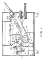
- Figure 1 shows an electrophotographic printer mechanism portion used in the apparatus for practicing the present invention.
- the printer mechanism comprises a photosensitive drum 3 as a latent image-bearing member rotating in the direction of an arrow shown in the figure; and a charger 4, a developing device 1M (or 1C, 1Y or 1BK), a transfer charger 10 and a cleaning device 12 disposed in this order along the peripheral surface of the photosensitive drum 3 with respect to the rotating direction thereof; and a laser beam scanner for providing a laser beam E disposed above (in the figure) the photosensitive drum 3, and other optional components.
- the laser beam scanner comprises a semiconductor laser portion, a polygon mirror rotating at a high speed, an f- ⁇ lens, a light-shielding plate (not shown), and other optional components.
- the semiconductor laser portion receives an input comprising a time series of digital pixel signals which has been operation-output from an image reader or computer and the like (not shown), and produces a pulse-width-modulated laser beam corresponding to the signals.
- the thus produced laser beam E is supplied to the surface of the drum 3 passing through a position between the charger 4 and the developing device 1M (or 1C, 1Y or 1BK), while scanning the drum surface in the direction of drum generatrix (i.e., the drum axis).
- Figure 7 shows a circuit diagram of a PWM circuit used in the apparatus in this embodiment
- Figure 8 shows a circuit diagram of a laser driver circuit used in such apparatus
- Figure 9 is a timing chart showing an operation of the PWM circuit.
- reference numeral 401 denotes a TTL latch circuit for latching an 8-bit image signal
- 402 denotes a level converter for converting TTL logic level to high-speed ECL logic level
- 403 denotes ECL D/A converter
- 404 denotes an ECL comparator for generating a PWM signal
- 405 denotes a level converter for converting ECL logic level to TTL logic level
- 406 denotes a clock oscillator for producing a twice frequency clock signal 2f of a pixel chock signal f
- 407 denotes a triangular wave signal generator for generating substantially ideal triangular wave signal in synchronism with the clock signal 2f
- 408 denotes a 1/2-frequency demultiplier for dividing the frequency of the clock signal 2f into 1/2 thereof.
- several ECL logic circuits are disposed therein.
- a signal denotes a clock signal 2f
- a signal b denotes a pixel clock signal f having a period which is 2 times larger than that of the clock signal 2f
- these signals are shown in connection with a pixel number.
- the frequency of the clock signal 2f is once divided into 1/2 and a triangular wave signal c is caused to generate. Further, the triangular wave signal c is converted into ECL level (0 to -1 V) to generate a triangular wave signal d.
- an image signal e denotes ECL voltage levels obtained by D/A-converting some image signal values.
- the first pixel denotes a voltage corresponding to "FFH” at a black pixel level
- the second pixel denotes a voltage corresponding to "80H” at a half-tone level
- the third pixel denotes a voltage corresponding to "40H” at a half-tone level
- the fourth pixel denotes a voltage corresponding to "20H" at a half-tone level.
- the comparator 404 compares the triangular wave signal d with the image signal e and generates a PWM signals having a pulse width such as T, t2, t3 and t4 corresponding to a pixel density to be provided. Then, the PWM signal is converted into TTL level of 0 V or 5 V to produce a PWM signal f, which is then input to a laser driver circuit 500.
- reference numeral 500 denotes a constant-current type laser driver circuit
- 501 denotes a semiconductor laser element.
- the semiconductor laser element emits a laser beam when a switching transistor 502 is turned on, and does not emit a laser beam when the switching transistor 502 is turned off.
- the switching transistor 502 constitutes a current switch circuit in combination with a transistor 504 to be paired therewith, and subjects a definite current to be supplied to the semiconductor laser element 501 to ON/OFF (commutation) control.
- the definite current is supplied from a constant-current supply transistor 505, and the value thereof is variable.
- the value of the definite current is determined by converting the eight-bit laser power value input to the driver circuit to an analog voltage by use of a D/A converter 503, and comparing it with a reference voltage.
- the response characteristic of the laser beam can pose a problem as follows.
- the minimum pulse width capable of providing a stable image density is limited.
- t3 10 ns
- a toner which comprises 90 % by volume or more of toner particles having a particle size r in a range satisfying 1/2M ⁇ r ⁇ 3/2M (i.e., in the range of M ⁇ M/2, M: volume-average particle size of the toner), and comprises 99 % by volume or more of toner particles satisfying 0 ⁇ r ⁇ 2M (i.e., in the range of M ⁇ M).
- a toner having a volume average particle size of below 12 microns (more preferably 10 microns or below, particularly preferably 8 microns or below).
- the volume-basis distribution and the volume-average particle size of a toner may for example be measured in the following manner.
- Coulter counter Model TA-II (available from Coulter Electronics Inc.) is used as an instrument for measurement, to which an interface (available from Nikkaki K.K.) for providing a number-basis distribution, a volume-basis distribution, a number-average particle size and a volume-average particle size, and a personal computer CX-1 (available from Canon K.K.) are connected.
- an interface available from Nikkaki K.K.
- CX-1 available from Canon K.K.
- a 1 %-NaCl aqueous solution as an electrolytic solution is prepared by using a reagent grade sodium chloride.
- a surfactant preferably an alkylbenzenesulfonic acid salt, is added as a dispersant, and 0.5 to 50 mg, of a sample is added thereto.
- the resultant dispersion of the sample in the electrolytic liquid is subjected to a dispersion treatment for about 1 - 3 minutes by means of an ultrasonic disperser, and then subjected to measurement of particle size distribution in the range of 2 - 40 microns by using the above-mentioned Coulter counter Model TA-II with a 100 microns-aperture to obtain a volume-basis distribution. From the results of the volume-basis distribution, the volume-average particle size of the sample toner are calculated.
- toner particles having a small particle size when toner particles having a small particle size are increased, the amount of the toner component which adheres to magnetic particles (carrier) and is difficult to be released therefrom is also increased, and the magnetic particles cannot effectively impart triboelectric charge to the toner, whereby toner scattering from a developing device and fog become marked. Further, because toner particles having a small particle size are liable to stick to the magnetic particles to increase fog and scattering due to carrier deterioration.
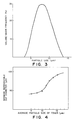
- Figure 4 is a graph showing relationship between an average particle size of a toner and a minimum reproducible dot diameter. The relationship as shown in Figure 4 has been obtained by the following experiment.
- the minimum reproducible dot diameter was not substantially affected even when a superposition of an AC bias and a DC bias, or a DC bias alone was used, or the kind of the carrier, the gap or clearance between a sleeve (developer-carrying member) and the drum or between the sleeve and a blade (developer thickness regulation means) are changed with respect to the respective toner particle size.
- toner particles having a small particle size are more liable to attach to such a portion. Further, toner particles having a small particle size form a thin layer on a transfer paper after the transfer thereof, and their adhesion force to the paper becomes stronger. As a result, even when the resultant toner image is subjected to an electric field for transfer plural times, toner scattering is less liable to occur.
- the reproducibility in a low-density portion remarkably change the impression of the whole image.
- the impression thereof is remarkably changed depending on whether dots of about 50 microns are faithfully reproduced or not.
- a toner having a volume-average particle size of 10 microns or below (more preferably 8 microns or below), because it may faithfully reproduce dots of about 50 microns as described in the above experiment, remarkably reduces toner scattering in a transfer step, thereby to provide a full-color image with high definition having sufficient gradational characteristic in its low-image density portion and having less coarsening or blurring, which has not been obtained in the prior art.
- the toner used has a volume-average particle size of 6 microns
- the toner used in the present invention having a sharp particle size distribution may be produced by melt-kneading prescribed materials for toner, cooling and pulverizing the kneaded product, and subjecting the pulverized product to precise classification to form a toner having a prescribed particle size distribution and/or volume-average particle size.
- the pulverized powder product may preferably be classified by a fixed-wall type wind-force classifier to obtain a classified powder product, and ultra-fine powder and coarse powder are simultaneously and precisely removed from the classified powder by means of a multi-division classifier utilizing a Coanda effect (e.g., Elbow Jet Classifier available from Nittetsu Kogyo K.K.), thereby to obtain a toner having a prescribed particle size distribution and/or volume-average particle size.
- a Coanda effect e.g., Elbow Jet Classifier available from Nittetsu Kogyo K.K.
- the term "toner” may include colored resin particles (comprising a binder resin and a colorant and another optional additive) per se, and colored resin particles to which an external additive such as hydrophobic colloidal silica has been externally added.
- the binder resin used for the toner may for example include: styrene-type copolymers such as styrene-acrylic acid ester resins and styrene-methacrylic acid ester resins; and polyester resins.
- particularly preferred resins may be polyester resins obtained through polycondensation of at least a diol component selected from bisphenol derivatives represented by the formula: wherein R denotes an ethylene or propylene group; x and y are respectively a positive integer of 1 or more providing the sum (x+y) of 2 to 10 on an average, and their substitution derivatives, and a two- or more-functioned carboxylic acid component or its anhydride or its lower alkyl ester, such as fumaric acid, maleic acid, maleic anhydride, phthalic acid, terephthalic acid and the like.
- Such polyester resins may show a sharp melting characteristic.
- colorant there may be used a dye or pigment which is generally used for an electrophotographic toner.
- Examples of the colorants suitable for the purpose of the present invention may include the following pigments or dyes.
- Examples of the dyes may include: C.I. Direct Red 1, C.I. Direct Red 4, C.I. Acid Red 1, C.I. Basic Red 1, C.I. Mordant Red 30, C.I. Direct Blue 1, C.I. Direct Blue 2, C.I. Acid Blue 9, C.I. Acid Blue 15, C.I. Basic Blue 3, C.I. Basic Blue 5, and C.I. Mordant Blue 7.
- pigments may include: Naphthol Yellow S, Hansa Yellow G, Permanent Yellow NCG, Permanent Orange GRT, Pyrazolone Orange, Benzidine Orange G, Permanent Red 4R, Watching Red calcium salt, Brilliant Carmine 3B, Fast Violet B, Methyl Violet Lake, Phthalocyanine Blue, Fast Sky Blue, and Indanthrene Blue BC.
- Particularly preferred pigments may include disazo yellow pigments, insoluble azo pigments and copper phthalocyanine pigments, and particularly preferred dyes may include basic dyes and oil soluble dyes.
- Particularly preferred examples may include: C.I. Pigment Yellow 17, C.I. Pigment Yellow 15, C.I. Pigment Yellow 13, C.I. Pigment Yellow 14, C.I. Pigment Yellow 12, C.I. Pigment Red 5, C.I. Pigment Red 3, C.I. Pigment Red 2, C.I. Pigment Red 6, C.I. Pigment Red 7, C.I. Pigment Blue 15, C.I. Pigment Blue 16, copper phthalocyanine pigments having two or three carboxybenzamidomethyl groups, and copper phthalocyanine pigments.
- dyes may include: C.I. Solvent Red 49, C.I. Solvent Red 52, C.I. Solvent Red 109, C.I. Basic Red 12, C.I. Basic Red 1 and C.I. Basic Red 3B.
- a yellow colorant for providing a yellow toner which sensitively affects the transparency of an OHP film, may preferably be used in a proportion of 0.1 to 12 wt. parts, more preferably 0.5 - 7 wt. parts, per 100 wt. parts of the binder resin.
- a proportion of more than 12 wt. parts provides a poor reproducibility of mixed colored of yellow, such as green, red and skin color.
- a magenta colorant and a cyan colorant for providing the magenta and cyan toners, respectively, may preferably be used in a proportion of 0.1 to 15 wt. parts, more preferably 0.1 - 9 wt. parts, per 100 wt. parts of the binder resin.
- the amount of the colorants in the black toner should preferably be 3 to 15 wt. parts per 100 wt. parts of the binder resin.
- a preferred combination of colorants for providing a black toner may be that of a disazo type yellow pigment, a monoazo-type red pigment and a copper phthalocyanine-type blue pigment.
- the proportional ratios of the yellow pigment, the red pigment and the blue pigment may preferably be 1:1.5 to 2.5:0.5 to 1.5.
- the disazo-type yellow pigment may be C.I. Pigment Yellow 17 or C.I. Pigment Yellow 13
- the monoazo-type red pigment may be C.I. Pigment Red 5 or C.I. Pigment Red 7
- the copper phthalocyanine-type blue pigment may be C.I. Pigment Blue 15.
- the magnetic charge control agent may for example be an organo-metal complex such as a metal complex of alkyl-substituted salicylic acid (e.g., chromium complex or zinc complex of di-tertiary-butylsalicylic acid).
- the negative charge control agent may be added to a toner in a proportion of 0.1 to 10 wt. parts, preferably 0.5 to 8 wt. parts, per 100 wt. parts of the binder resin.
- the carrier may preferably comprise magnetic particles.
- the magnetic particles may preferably be those comprising ferrite particles (maximum magnetization: 60 emu/g) which have been coated with a resin so that they have a particle size of 30 100 microns, more preferably 40 - 80 microns, an electric resistivity of 107 ohm.cm or more, more preferably 108 ohm.cm or more.
- the resistivity of the magnetic particles is measured with a sandwiching-type cell having a measuring electrode area of 4 cm2 and having a clearance of 0.4 cm between the electrodes.
- One of the electrodes is imparted with 1 kg weight, and a voltage E (V/cm) is applied across the electrodes, and the resistivity of the magnetic particles is determined from the current through the circuit.
- Figure 1 schematically shows the whole arrangement of an electrophotographic color printer as an example of the image forming apparatus in which a developing device according to the present invention is assembled.
- a rotation-type developing device 1 comprises a yellow developing device 1Y, a magenta developing device 1M, a cyan developing device 1C and a black developing device 1BK.
- reference numeral 3 denotes a photosensitive drum rotating in the direction of an arrow shown in the figure, and the photosensitive material disposed on the drum 3 is uniformly charged by means of a charger 4.
- the drum 3 is then imagewise exposed to a laser light E modulated according to a "magenta" image signal from an original (not shown), to form thereon an electrostatic latent image, which is then developed by means of the magenta developing device which has been disposed at a developing position where the drum 3 is disposed opposite thereto, in advance, thereby to form a magenta image.
- a transfer paper (or transfer-receiving paper) is fed to a gripper 7 through the medium of a paper supply guide 5a, a paper supply roller 6 and a paper supply guide 5b.
- the transfer paper is held by the gripper 7 in synchronism with a prescribed timing, and is electrostatically wound around a transfer drum 9 by means of a contact roller 8 and an electrode disposed opposite thereto.
- the transfer drum 9 is rotated in the direction of an arrow shown in the figure in synchronism with the rotation of the photosensitive drum 3.
- the magenta image developed by the magenta developing device 1M in the above-mentioned manner is transferred from the photosensitive drum 3 to the transfer paper disposed on the transfer drum 9, by means of a transfer charger 10.
- the transfer drum 9 continues its rotation as such and provides for transfer of the next color (e.g., a cyan color in the embodiment shown in Figure 1).
- the photosensitive drum 3 is discharged by means of a charger 11, and cleaned by a cleaning member 12. Thereafter, the drum 3 is again charged by means of the charger 4, and exposed to light modulated according to a "cyan" image signal in the same manner as described above. During such operation, the developing device 1 is rotated to dispose the cyan developing device 1C at the developing position, whereby a prescribed "cyan" development is conducted. Then, the above-mentioned procedure is repeated with respect to yellow and black colors.
- the transfer paper having thereon the developed image comprising the four colors is discharged by means of chargers 13 and 14 is released from the above-mentioned gripper 7 and separated from the transfer drum 9 by means of a separation claw 15. Then, the thus separated transfer paper is conveyed to a fixing device (hot roller fixing device) 17 by a conveyer belt 16, whereby a series of full-color print sequence is completed and a desired full-color print image is formed.
- a fixing device hot roller fixing device
- Figure 2 is an enlarged sectional view of image forming apparatus in the neighborhood of the developing device.
- a latent image bearing member 1 is driven in the direction indicated by an arrow a by an unshown driving device.
- the developing device includes a developing sleeve 22 which is disposed opposite to the image bearing member 1 and is made of non-magnetic material such as aluminum, SUS 316 (stainless steel, JIS).
- the developing sleeve 22 is in a longitudinal opening formed in a lower left wall of a developer container 36, and about a right half peripheral surface is in the container 36, whereas about a left half peripheral surface thereof is exposed outside.
- the developing sleeve 22 is rotatably supported and is driven in the direction indicated by an arrow b .
- the developing device further includes a stationary magnetic field generating means 23 in the form of a stationary permanent magnet within the developing sleeve 22.
- the permanent magnet 23 is fixed and is maintained stationary even when the developing sleeve 22 is rotated.
- the magnet 23 has an N-pole 23a, S-pole 23b, N-pole 23c and an S-pole 23d, that is, it has four poles.
- the magnet 23 may be an electromagnetic in place of the permanent magnet.
- a non-magnetic blade 24 has a base portion fixed to a side wall of the container adjacent a top edge of the opening in which the developing sleeve 22 is disposed, and a free end extending at a top edge of the opening.
- the blade 24 serves to regulate the developer carried on the developing sleeve 22.
- the non-magnetic blade is made by, for example, bending to "L" shape a stainless steel plate (SUS316).
- the developing device includes a magnetic carrier particle limiting member 26 which is disposed so that the upper surface thereof contacts the lower surface of the non-magnetic blade 24.
- the bottom surface 261 of the limiting member 26 constitutes a developer guiding surface.
- the non-magnetic blade 24, the magnetic particle limiting member 26, etc., define a developer regulating station.
- the reference numeral 27 designates magnetic carrier particles having a resistivity of not less than 107 ohm.cm, preferably not less than 108 ohm.cm, more preferably 109 - 1012 ohm.cm.
- reference numeral 37 designates non-magnetic toner.
- a sealing member 40 is effective to prevent the toner stagnating adjacent the bottom of the developer container 36 from leaking.
- the sealing member 40 is bent co-directionally with the rotation of the sleeve 22, and is resiliently pressed onto the surface of the sleeve 22.
- the sealing member 40 has its end portion at a downstream side in the region where it is contacted to the sleeve 22 so as to allow the developer returning into the container.
- An electrode plate 30 for preventing scattering of the floating toner particles produced by the developing process is supplied with a voltage having a polarity which is the same as the polarity of the toner to cause the toner particles to be deposited on the photosensitive member.
- a toner supplying roller 60 is operative in response to an output of an unshown toner content detecting sensor.
- the sensor may be, for example, of a developer volume detecting type, a piezoelectric element type, an inductance change detecting type, an antenna type utilizing an alternating bias, or an optical density detecting type.
- the S-pole 23d is a conveying pole for collecting the developer remaining after the developing operation back into the container, and to convey the developer in the container to the regulating portion, by the magnetic field provided thereby.
- the fresh developer conveyed by the screw 162 adjacent the sleeve 22 replaces the developer on the sleeve 22 collected after the development.
- a conveying screw 64 is effective to make uniform the distribution of the developer amount along the length of the developing sleeve.
- the developer conveyed on the sleeve together with the rotation of the sleeve is conveyed along the length of the sleeve by the screw 64.
- the developer layer portion which is partly thick along the longitudinal direction of the sleeve is partly returned in the direction opposite to the sleeve movement through the space M in Figure 2.
- the screw 24 conveys the developer in the direction opposite to that of the screw 62.
- This structure is effective also when magnetic particles and non-magnetic or weakly magnetic toner particles are mixed in the developer container.
- the distance d2 between the edge of the non-magnetic blade 24 and the surface of the developing sleeve 22 is 50 - 900 microns, preferably 150 - 800 microns. If the distance is smaller than 50 microns, the magnetic carrier particles may clog the clearance to easily produce non-uniform developer layer, and to prevent application of sufficient amount of the developer with the result of low density and non-uniform density image. Further, the clearance d2 is preferably not less than 400 microns since then it can be avoided that a non-uniform developer layer (clogging at the blade) is produced by foreign matter such as agglomerates of toner-particles and dust contained in the developer.
- the distance is larger than 900 microns, the amount of the developer applied on the developing sleeve 22 is increased too much, and therefore, proper regulation of the thickness of the developer layer can not be performed, and the amount of the magnetic particles deposited on the latent image bearing member is increased, and simultaneously, the circulation of the developer which will be described hereinafter and the regulation of the circulation by the developer limiting member 26 are weakened with the result of insufficient triboelectric charge leading to production of foggy background.
- a line L1 is a line connecting a rotational center of the sleeve 22 and the center of the developer layer thickness regulating pole 23a, that is, the maximum magnetic flux density position on the sleeve surface;
- a line L2 is a line connecting the rotational center of the sleeve 22 and the free edge of the blade 24; and
- an angle ⁇ 1 is an angle formed between the lines L1 and L2.
- the angle ⁇ 1 is within the range of -5 to 35 degrees, preferably 0 to 25 degrees.
- the ⁇ 1 is smaller than -5 degrees, the developer layer formed by the magnetic force, mirror force and/or coagulating force applied to the developer becomes non-uniform, whereas if it is larger than 35 degrees, the amount of application of the developer on the sleeve by a non-magnetic blade is increased with the result of difficulty in providing a predetermined amount of developer.
- the negative of the angle ⁇ 1 means that the line L1 is disposed downstream of the line L2 with respect to the rotational direction of the sleeve 22.
- the speed of the developer layer on the sleeve 22 becomes lower away from the sleeve surface due to the balance between the conveying force by the sleeve 22 and the gravity and the magnetic force against it, even though the sleeve 22 is rotated in the direction indicated by an arrow b . Some part of the developer falls by the gravity.
- the magnetic particle layer is moved more in the position closer to the sleeve 22, to constitute a moving layer.
- the magnetic particles and toner particles are conveyed to a developing position together with the rotation of the sleeve 2, and is provided for the developing operation.
- Figure 5 shows another apparatus embodiment.
- the apparatus shown in Figure 5 comprises four photosensitive members 3Y (yellow), 3M (magenta), 3C (cyan) and 3BK (black), respectively used for these four colors.
- a transfer paper (not shown) is passed through a paper supply guide 5a, and conveyed by a paper supply roller 6, and a paper supply guide 5b in this order to a conveyor belt ga.
- the transfer paper is subjected to corona discharge by a charger for attachment 81 and is surely attached to the conveyor belt ga.
- toner images of four colors formed on the four photosensitive members 3Y, 3M, 3C and 3BK are transferred to the transfer paper by means of the transfer chargers 10Y, 10M, 10C and 10BK, respectively.
- the transfer paper having thereon the thus transferred toner image is discharged by a discharger 82 and separated from the conveyor belt 9a, and the toner image is fixed to the transfer paper by a fixing device 17 thereby to provide a full-color image.
- a toner having an average particle size of 8 microns or below provided similar results.
- a toner having a particle size distribution and a particle size (e.g., a volume-average particle size of 6 microns) satisfying the condition defined by the present invention was used, the clearance d2 between the end of a non-magnetic blade 24 and the surface of a photosensitive drum 3 (laminate type organic photoconductor (OPC) drum) was set to 600 microns, and the clearance between the photosensitive drum 3 and the surface of the sleeve 22 was set to 450 microns.
- the drum 3 was charged to provide a latent image potential of -600 V.
- a bias power supply 4 providing a superposition of a rectangular alternating voltage having a frequency of 1700 Hz and a peak-to-peak value of 1500 V on a DC voltage of -300 V.
- an image forming method using a multi-color electrophotographic apparatus wherein an original image is subjected to color separation and the resultant light beams (such as laser beam) are provided to a photosensitive drum to form thereon latent images corresponding to the respective colors, the latent images are developed with developer particles to form toner images of respective colors, which are then multiply transferred to a transfer material sequentially, thereby to provide a multi color image.
- the resultant light beams such as laser beam
- a toner having a volume-average particle size of 8 microns or below (particularly, one also having a sharp article size distribution) is used as the above-mentioned developer, and the light beam is pulse-width-modulated in accordance with an image signal to obtain a half-tone image.
- a mixture containing the above ingredients in the prescribed amounts was melt-kneaded. After cooling, the kneaded product was pulverized and the pulverized product was classified by means of a fixed-wall type wind-force classified and further classified by means of a multi-division classifier utilizing a Coanda effect to obtain negatively chargeable magenta toner having a volume-average particle size of 6 microns.
- magenta toner had a sharp particle size distribution such that it contained 95 % by volume of particles having a particle size of above 3 microns and below 9 microns, and substantially 100 % by volume of particles having a particle size of above 0 microns and below 12 microns.
- 0.4 wt. part of negatively chargeable hydrophobic colloidal silica was mixed with 100 wt. parts of the above-mentioned magenta toner to prepare a magenta toner containing externally added silica (i.e., external addition product). Then, 6 wt. parts of the magenta toner (external addition product) was mixed with 94 wt. parts of ferrite magnetic particles coated with a styrene-acrylic acid ester copolymer (weight-average particle size: 50 microns, electric resistivity: 1010 ohm/cm) to prepare a two-component developer for forming a magenta toner image.
- cyan, yellow and black colorants shown in the following Table 1 a two-component developer for forming a cyan toner image, a two-component developer for forming a yellow toner image; and a two-component developer for forming a black toner image were respectively prepared in the same manner as described above.
- Table 1 Colorant Volume-average particle size of toner M ( ⁇ m) % by volume of toner particles satisfying 1/2M ⁇ (particle size) ⁇ 3/2M % by volume of toner particles satisfying 0 ⁇ (particle size) ⁇ 2M Cyan toner Phthalocyanine-type pigment 6 95 100 Yellow toner Pigment Yellow-type pigment 6 95 100 Black toner Pigment Yellow-type pigment, Pigment Red-type pigment, and Pigment Blue-type pigment 6 95 100
- the above-mentioned two-component developers were respectively poured into a polyethylene container (volume: 100 ml) and vigorously shaken about 30 times by hands, and the triboelectric charge amounts were respectively measured.
- the toners of respective colored showed a charge amount of -30 ⁇ c/g.
- the clearance d2 between the end of a non-magnetic blade 24 and the surface of a photosensitive drum 3 was set to 600 microns, and the clearance between the photosensitive drum 3 and the surface of a sleeve 22 was set to 450 microns.
- the drum 3 was charged to provide a latent image potential of -600 V.
- a bias power supply 4 providing a superposition of a rectangular alternating voltage having a frequency of 1700 Hz and a peak-to-peak value of 1500 V on a DC voltage of -300 V.
- the thus obtained latent image was developed by a reversal developing method and the resultant toner image was electrostatically transferred to a transfer paper. Such a procedure was sequentially repeated with respect to respective colors, and the resultant multi-color toner image was finally fixed by means of a hot roller fixing device to obtain a full-color image. As a result, there was obtained a high-quality image with a high definition which was free of coarsening and had a low image density portion (i.e., highlight portion) faithfully reproduced.
- Toners having volume-average particle sizes of 5 microns, 6.8 microns and 8 microns, respectively, as shown in Figure 4 and the following Table 2 were prepared in a similar manner as in Example 1, and were subjected to full-color image formation in the same manner as in Example 1. As a result, good results were obtained.
- Table 2 Volume-average particle size of toner M ( ⁇ m) % by volume of toner particles satisfying 1/2M ⁇ (particle size) ⁇ 3/2 M % by volume of toner particles satisfying 0 ⁇ (particle size) ⁇ 2M
- Example 4 8 96 100
- Toners of respective colors having a volume-average particle size of 12 microns as shown the following Table 3 were prepared in a similar manner as in Example 1.
- two-component developers of respective colors were prepared in the same manner as in Example 1 and were subjected to full-color image formation in the same manner as in Example 1.
- the above-mentioned two-component developers were respectively poured into a polyethylene container (volume: 100 ml) and vigorously shaken about 30 times by hands, and the triboelectric charge amounts were respectively measured.
- the toners of respective colors showed a charge amount of -16 to -18 ⁇ c/g, which was lower than that obtained in Example 1.
- minimum diameter of dots which had been faithfully reproduced corresponding to the latent image was about 90 microns.
- Toners of respective colors having a volume-average particle sizes of 9 microns as shown in the following Table 4 were prepared in a similar manner as in Example 1.
- two-component developers were prepared in the same manner as in Example 1, and the thus obtained developers were subjected to full-color image formation in the same manner as in Example 1.
- high-quality and high-definition images free of coarsening which had a low-density portion (i.e., highlight portion) faithfully reproduced, while they were somewhat inferior to those obtained in Example 1.
Landscapes
- Engineering & Computer Science (AREA)
- Multimedia (AREA)
- Signal Processing (AREA)
- Physics & Mathematics (AREA)
- General Physics & Mathematics (AREA)
- Optics & Photonics (AREA)
- Developing Agents For Electrophotography (AREA)
- Color Electrophotography (AREA)
- Color, Gradation (AREA)
- Facsimile Image Signal Circuits (AREA)
Applications Claiming Priority (4)
| Application Number | Priority Date | Filing Date | Title |
|---|---|---|---|
| JP63054821A JPH0284363A (ja) | 1988-03-10 | 1988-03-10 | 画像形成装置 |
| JP54821/88 | 1988-03-10 | ||
| JP18256288 | 1988-07-20 | ||
| JP182562/88 | 1988-07-20 |
Publications (3)
| Publication Number | Publication Date |
|---|---|
| EP0332428A2 true EP0332428A2 (de) | 1989-09-13 |
| EP0332428A3 EP0332428A3 (de) | 1991-01-02 |
| EP0332428B1 EP0332428B1 (de) | 1994-07-06 |
Family
ID=26395633
Family Applications (1)
| Application Number | Title | Priority Date | Filing Date |
|---|---|---|---|
| EP89302318A Revoked EP0332428B1 (de) | 1988-03-10 | 1989-03-08 | Bilderzeugungsverfahren |
Country Status (3)
| Country | Link |
|---|---|
| US (1) | US5327339A (de) |
| EP (1) | EP0332428B1 (de) |
| DE (1) | DE68916562T2 (de) |
Cited By (7)
| Publication number | Priority date | Publication date | Assignee | Title |
|---|---|---|---|---|
| EP0400555A3 (de) * | 1989-05-30 | 1992-02-05 | Canon Kabushiki Kaisha | Bilderzeugungsgerät |
| GB2251085A (en) * | 1990-11-30 | 1992-06-24 | Fuji Xerox Co Ltd | Color toner for slide preparation |
| US5313233A (en) * | 1989-05-30 | 1994-05-17 | Canon Kabushiki Kaisha | Image forming apparatus |
| EP0716536A3 (de) * | 1994-12-07 | 1996-11-06 | Canon Kk | Bilderzeugungsgerät und Prozesskartusche |
| EP0769727A1 (de) * | 1995-10-20 | 1997-04-23 | Fuji Xerox Co., Ltd. | Toner zur vielfarbigen Bilderzeugung, Entwicklerzusammensetzung und Mehrfarbenbildherstellungsverfahren |
| EP0772092A1 (de) * | 1995-11-02 | 1997-05-07 | Fuji Xerox Co., Ltd. | Toner für elektrostatische Bildentwicklung, Entwickler für elektrostatische Bilder, und Bildherstellungsverfahren unter Verwendung derselben |
| EP0780734A3 (de) * | 1995-12-18 | 1997-07-23 | Fuji Xerox Co., Ltd. | Entwickler für elektrostatische Bilder und Bildaufzeichnungsverfahren |
Families Citing this family (6)
| Publication number | Priority date | Publication date | Assignee | Title |
|---|---|---|---|---|
| JP2547916B2 (ja) * | 1992-01-08 | 1996-10-30 | 株式会社東芝 | 画像形成装置 |
| JPH07271137A (ja) * | 1994-03-26 | 1995-10-20 | Canon Inc | 画像形成装置 |
| US5969746A (en) * | 1995-12-18 | 1999-10-19 | Fuji Xerox Co., Ltd. | Image forming apparatus for reproducing halftone images |
| JPH09197756A (ja) * | 1996-01-19 | 1997-07-31 | Canon Inc | 画像形成装置 |
| WO2001007969A1 (fr) * | 1999-07-23 | 2001-02-01 | Fujitsu Limited | Dispositif de formation d'images et machine a developper |
| US6590600B2 (en) * | 2001-03-16 | 2003-07-08 | Eastman Kodak Company | Method and apparatus for controlling exposure amplitude and printed track width by pulse width modulation |
Family Cites Families (10)
| Publication number | Priority date | Publication date | Assignee | Title |
|---|---|---|---|---|
| NL7707547A (nl) * | 1977-07-07 | 1979-01-09 | Oce Van Der Grinten Nv | Werkwijze voor het magnetisch transfereren van een poederbeeld. |
| DE3051020C2 (de) * | 1979-03-09 | 1988-11-17 | Canon K.K., Tokio/Tokyo, Jp | |
| JPS57158004A (en) * | 1981-03-24 | 1982-09-29 | Toshiba Corp | Magnetic transfer recorder |
| DE3379747D1 (en) * | 1982-08-31 | 1989-06-01 | Mita Industrial Co Ltd | Method for developing electrostatic latent images |
| US4557992A (en) * | 1984-03-26 | 1985-12-10 | Konishiroku Photo Industry Co., Ltd. | Developing method |
| DE3546358A1 (de) * | 1984-12-31 | 1986-07-03 | Konishiroku Photo Industry Co. Ltd., Tokio/Tokyo | Verfahren und vorrichtung zur bildformung |
| US4800442A (en) * | 1985-08-15 | 1989-01-24 | Canon Kabushiki Kaisha | Apparatus for generating an image from a digital video signal |
| EP0533299B1 (de) * | 1985-08-15 | 1997-01-29 | Canon Kabushiki Kaisha | Vorrichtung zur Verarbeitung und Wiedergabe digitaler Videosignale, mit auf den Pixeltakt synchronisierter Pulsbreitenmodulation zur Erzeugung eines binären Signals aus Halbton-Bilddaten |
| EP0227006B1 (de) * | 1985-12-17 | 1991-03-13 | Konica Corporation | Verfahren zur Entwicklung elektrostatischer latenter Bilder |
| JP2621864B2 (ja) * | 1987-04-01 | 1997-06-18 | 株式会社リコー | デジタルカラー複写機 |
-
1989
- 1989-03-08 DE DE68916562T patent/DE68916562T2/de not_active Expired - Fee Related
- 1989-03-08 EP EP89302318A patent/EP0332428B1/de not_active Revoked
-
1993
- 1993-01-19 US US08/003,944 patent/US5327339A/en not_active Expired - Lifetime
Cited By (11)
| Publication number | Priority date | Publication date | Assignee | Title |
|---|---|---|---|---|
| EP0400555A3 (de) * | 1989-05-30 | 1992-02-05 | Canon Kabushiki Kaisha | Bilderzeugungsgerät |
| US5313233A (en) * | 1989-05-30 | 1994-05-17 | Canon Kabushiki Kaisha | Image forming apparatus |
| GB2251085A (en) * | 1990-11-30 | 1992-06-24 | Fuji Xerox Co Ltd | Color toner for slide preparation |
| GB2251085B (en) * | 1990-11-30 | 1994-07-20 | Fuji Xerox Co Ltd | Color toner for slide preparation |
| EP0716536A3 (de) * | 1994-12-07 | 1996-11-06 | Canon Kk | Bilderzeugungsgerät und Prozesskartusche |
| US5818489A (en) * | 1994-12-07 | 1998-10-06 | Canon Kabushiki Kaisha | Image forming apparatus and process cartridge having exposure device using light beam having specific spot area |
| EP0769727A1 (de) * | 1995-10-20 | 1997-04-23 | Fuji Xerox Co., Ltd. | Toner zur vielfarbigen Bilderzeugung, Entwicklerzusammensetzung und Mehrfarbenbildherstellungsverfahren |
| US5738962A (en) * | 1995-10-20 | 1998-04-14 | Fuji Xerox Co., Ltd. | Toner for full-color image formation, developer composition, and method of forming multicolor image |
| EP0772092A1 (de) * | 1995-11-02 | 1997-05-07 | Fuji Xerox Co., Ltd. | Toner für elektrostatische Bildentwicklung, Entwickler für elektrostatische Bilder, und Bildherstellungsverfahren unter Verwendung derselben |
| US5804351A (en) * | 1995-11-02 | 1998-09-08 | Fuji Xerox Co., Ltd. | Toner for electrostatic-image development, developer for electrostatic image, and image forming process using the same |
| EP0780734A3 (de) * | 1995-12-18 | 1997-07-23 | Fuji Xerox Co., Ltd. | Entwickler für elektrostatische Bilder und Bildaufzeichnungsverfahren |
Also Published As
| Publication number | Publication date |
|---|---|
| DE68916562T2 (de) | 1994-11-24 |
| EP0332428A3 (de) | 1991-01-02 |
| US5327339A (en) | 1994-07-05 |
| DE68916562D1 (de) | 1994-08-11 |
| EP0332428B1 (de) | 1994-07-06 |
Similar Documents
| Publication | Publication Date | Title |
|---|---|---|
| US4680625A (en) | Method and apparatus for multicolor image forming | |
| EP0332428B1 (de) | Bilderzeugungsverfahren | |
| US5576812A (en) | Developing method with carrier chains contacted to image bearing member | |
| US5172132A (en) | Digital image forming device and method for forming an image from a plurality of dots | |
| JPH0535038A (ja) | 電子写真装置 | |
| US5313233A (en) | Image forming apparatus | |
| JPH0713420A (ja) | 現像装置 | |
| US5438394A (en) | Image forming apparatus usable with a carrier having magnetization controlled in relation to recording density | |
| JP2668440B2 (ja) | 画像形成装置 | |
| JP2763321B2 (ja) | 画像形成方法 | |
| EP0400555B1 (de) | Bilderzeugungsgerät | |
| US5268709A (en) | Image forming apparatus | |
| JPH05289522A (ja) | 画像形成装置 | |
| JP2899503B2 (ja) | 画像形成装置 | |
| JPS61223853A (ja) | 多色画像形成方法 | |
| JPH08146757A (ja) | 現像装置 | |
| JPH04147286A (ja) | 現像装置、及び画像形成装置 | |
| JP2668440C (de) | ||
| JP3226740B2 (ja) | 画像形成方法 | |
| JPH05333688A (ja) | 画像形成装置 | |
| JP3093512B2 (ja) | 現像装置 | |
| US6136487A (en) | Developing method | |
| JP3217252B2 (ja) | 画像形成装置 | |
| JPH07295320A (ja) | 画像形成装置 | |
| JPH032763A (ja) | 画像形成方法 |
Legal Events
| Date | Code | Title | Description |
|---|---|---|---|
| PUAI | Public reference made under article 153(3) epc to a published international application that has entered the european phase |
Free format text: ORIGINAL CODE: 0009012 |
|
| AK | Designated contracting states |
Kind code of ref document: A2 Designated state(s): DE FR GB IT |
|
| PUAL | Search report despatched |
Free format text: ORIGINAL CODE: 0009013 |
|
| AK | Designated contracting states |
Kind code of ref document: A3 Designated state(s): DE FR GB IT |
|
| 17P | Request for examination filed |
Effective date: 19901231 |
|
| 17Q | First examination report despatched |
Effective date: 19921105 |
|
| GRAA | (expected) grant |
Free format text: ORIGINAL CODE: 0009210 |
|
| AK | Designated contracting states |
Kind code of ref document: B1 Designated state(s): DE FR GB IT |
|
| REF | Corresponds to: |
Ref document number: 68916562 Country of ref document: DE Date of ref document: 19940811 |
|
| ITF | It: translation for a ep patent filed | ||
| ET | Fr: translation filed | ||
| PLBI | Opposition filed |
Free format text: ORIGINAL CODE: 0009260 |
|
| 26 | Opposition filed |
Opponent name: AGFA-GEVAERT N.V. Effective date: 19950323 |
|
| PLBF | Reply of patent proprietor to notice(s) of opposition |
Free format text: ORIGINAL CODE: EPIDOS OBSO |
|
| RDAH | Patent revoked |
Free format text: ORIGINAL CODE: EPIDOS REVO |
|
| APAC | Appeal dossier modified |
Free format text: ORIGINAL CODE: EPIDOS NOAPO |
|
| APAE | Appeal reference modified |
Free format text: ORIGINAL CODE: EPIDOS REFNO |
|
| APAC | Appeal dossier modified |
Free format text: ORIGINAL CODE: EPIDOS NOAPO |
|
| APCC | Communication from the board of appeal sent |
Free format text: ORIGINAL CODE: EPIDOS OBAPO |
|
| APAC | Appeal dossier modified |
Free format text: ORIGINAL CODE: EPIDOS NOAPO |
|
| RDAH | Patent revoked |
Free format text: ORIGINAL CODE: EPIDOS REVO |
|
| APAC | Appeal dossier modified |
Free format text: ORIGINAL CODE: EPIDOS NOAPO |
|
| APAE | Appeal reference modified |
Free format text: ORIGINAL CODE: EPIDOS REFNO |
|
| APAC | Appeal dossier modified |
Free format text: ORIGINAL CODE: EPIDOS NOAPO |
|
| APAC | Appeal dossier modified |
Free format text: ORIGINAL CODE: EPIDOS NOAPO |
|
| PLBQ | Unpublished change to opponent data |
Free format text: ORIGINAL CODE: EPIDOS OPPO |
|
| PLAB | Opposition data, opponent's data or that of the opponent's representative modified |
Free format text: ORIGINAL CODE: 0009299OPPO |
|
| R26 | Opposition filed (corrected) |
Opponent name: XEIKON NV Effective date: 19950323 |
|
| REG | Reference to a national code |
Ref country code: GB Ref legal event code: IF02 |
|
| PLBQ | Unpublished change to opponent data |
Free format text: ORIGINAL CODE: EPIDOS OPPO |
|
| PLAB | Opposition data, opponent's data or that of the opponent's representative modified |
Free format text: ORIGINAL CODE: 0009299OPPO |
|
| PLAB | Opposition data, opponent's data or that of the opponent's representative modified |
Free format text: ORIGINAL CODE: 0009299OPPO |
|
| PGFP | Annual fee paid to national office [announced via postgrant information from national office to epo] |
Ref country code: GB Payment date: 20040223 Year of fee payment: 16 |
|
| R26 | Opposition filed (corrected) |
Opponent name: XEIKON NV Effective date: 19950323 |
|
| PGFP | Annual fee paid to national office [announced via postgrant information from national office to epo] |
Ref country code: DE Payment date: 20040319 Year of fee payment: 16 |
|
| PGFP | Annual fee paid to national office [announced via postgrant information from national office to epo] |
Ref country code: FR Payment date: 20040322 Year of fee payment: 16 |
|
| R26 | Opposition filed (corrected) |
Opponent name: XEIKON INTERNATIONAL NV Effective date: 19950323 |
|
| APBU | Appeal procedure closed |
Free format text: ORIGINAL CODE: EPIDOSNNOA9O |
|
| RDAG | Patent revoked |
Free format text: ORIGINAL CODE: 0009271 |
|
| STAA | Information on the status of an ep patent application or granted ep patent |
Free format text: STATUS: PATENT REVOKED |
|
| 27W | Patent revoked |
Effective date: 20040218 |
|
| GBPR | Gb: patent revoked under art. 102 of the ep convention designating the uk as contracting state |
Free format text: 20040218 |
|
| APAH | Appeal reference modified |
Free format text: ORIGINAL CODE: EPIDOSCREFNO |